Project Description:
This is a tablet PC based on the Allwinner A133 processor, capable of running Android and Linux systems. It features a 7-inch 1024x600 resolution touchscreen LCD and a 3000mAh battery. It includes dual-band Wi-Fi 6 and Bluetooth 5.2 modules, 2GB of RAM, a built-in 32GB eMMC drive, supports external TF cards, and is powered via a Type-C port.
Video Link: https://www.bilibili.com/video/BV1c8411d7L9/
Open Source License
: This project is licensed under the Creative Commons Attribution-NonCommercial-ShareAlike 4.0 license. Commercial use is prohibited. Please indicate the source when reprinting.
Project Attributes:
This is the first public release of this project, and it is my original work. This project has not won any awards in other competitions.
Project Progress: Project initiation
began on May 14th, requirements were determined.
Schematic design completed on June 21st.
PCB design completed on July 3rd, sent for prototyping.
PCB redesigned on July 4th; 3mil trace width was not free and was changed to 3.5mil with rerouting. Components purchased.
The 3D shell design was completed on July 8th and sent to 3D Prototyping Center.
The PCB arrived on July 9th, and components arrived gradually; BGA soldering began.
From July 10th to 14th, soldering failed; DDR and ball-mounting stencils were repurchased, but the DDR test at 888MHz failed randomly.
On July 15th, the PCB was remade at JLCPCB using SMT, and the system awaited delivery.
From July 23rd to 28th, the PCB arrived, but the user was on a business trip.
On July 29th, the DDR 888MHz test was successful; the remaining components were soldered. The Android system was flashed, and Wi-Fi, 3.5mm audio jack, and USB functions were tested.
On August 14th, a backplate was designed for copper heat dissipation; the effect is unknown. Project Introduction:
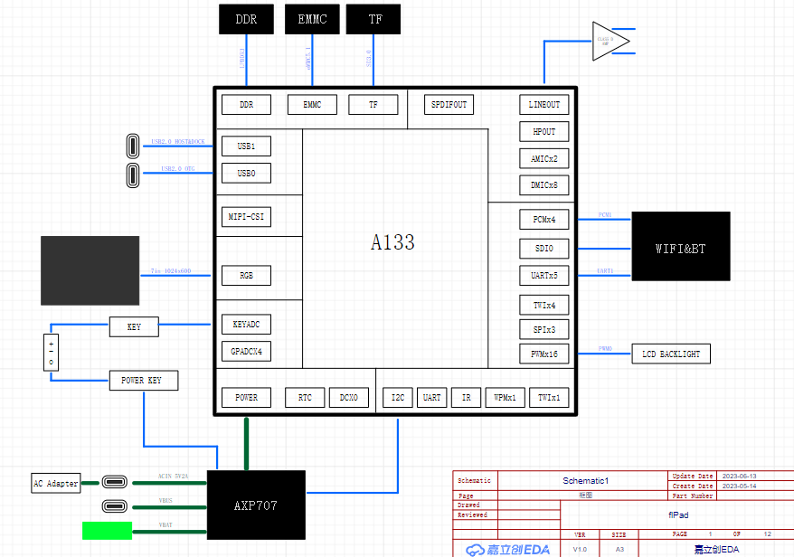
1. The hardware
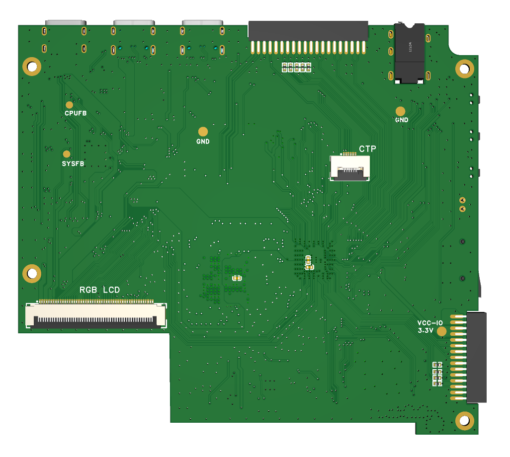
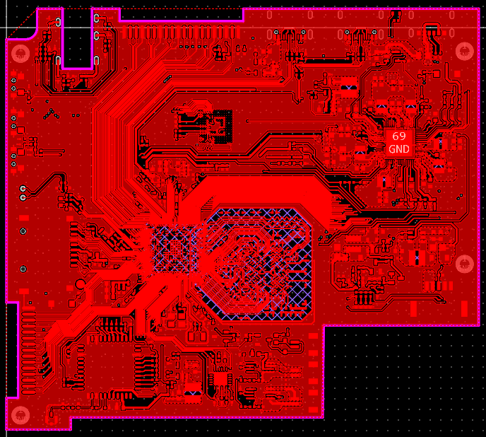
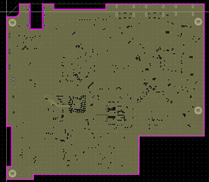
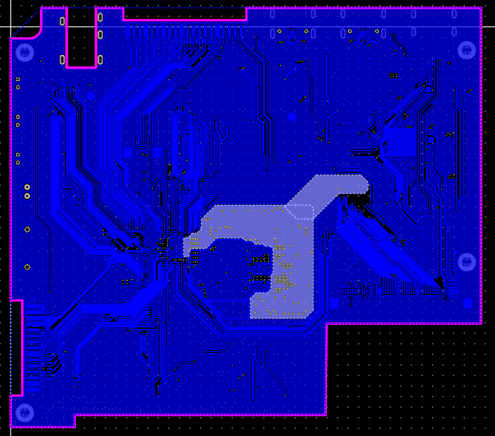
PCB was designed according to JLCPCB's 4-layer board free prototyping rules, using 3313 lamination, 1.2mm thickness, 3.5mil trace width and spacing, 0.3/0.4mm vias, and a size within 10x10mm. The components are mainly arranged on the front for easy surface mount processing, while the back is the FPC connector for the display screen.
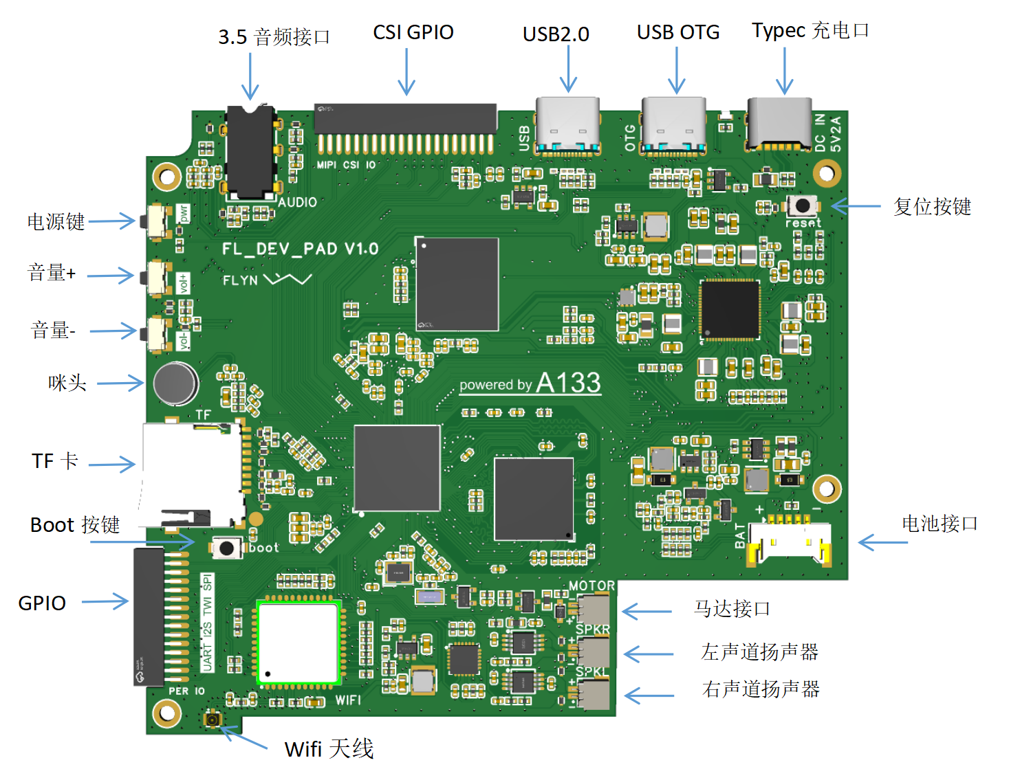
1.1 Frame
1.2 Structure
Considering cost and adaptability to different needs, the casing is designed with three parts: outer frame, middle layer, and back plate. The outer frame is made of PLA engineering plastic, which has high rigidity. The middle layer uses X resin SLA photosensitive resin material, which is low-cost. For heat dissipation requirements, the back plate can be made of CNC aluminum profile, which can be directly attached to the processor and DDR. For lower cost, PLA or SLA can be chosen.
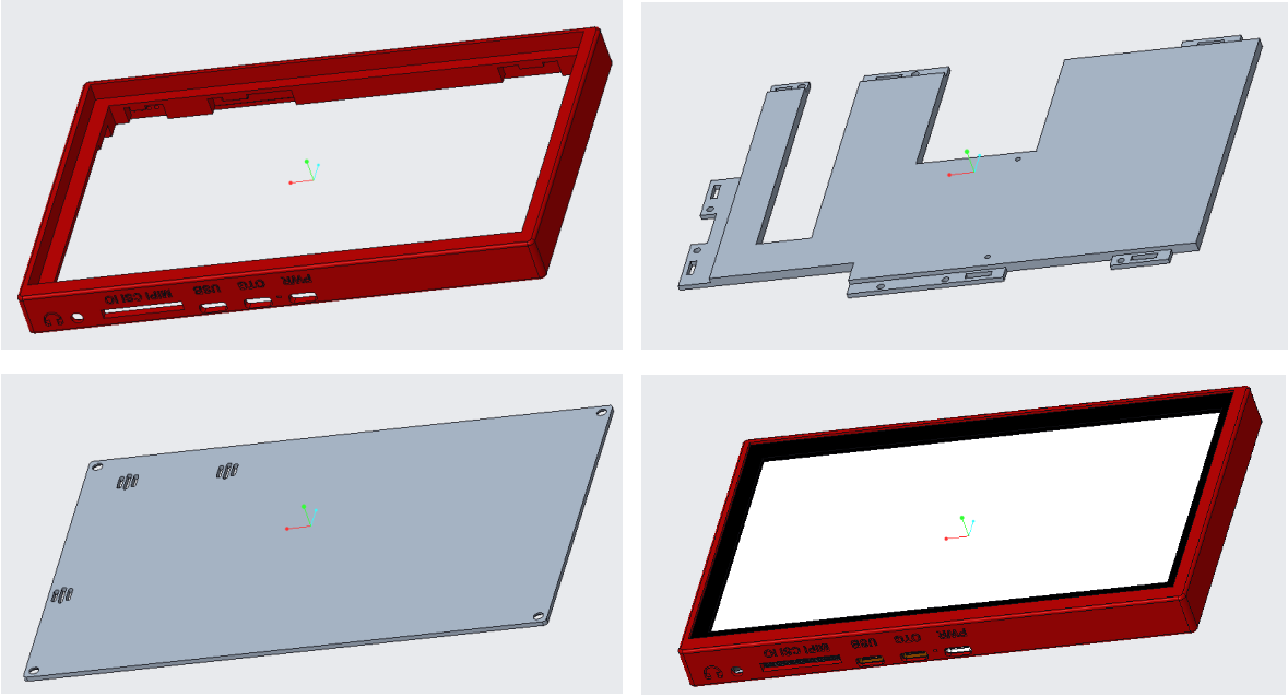
The middle layer is clipped onto the outer frame as a fixing bracket for the PCB and display screen. If you feel it's not secure enough, you can use small screws to further secure it. The display screen is directly clipped onto the outer frame. The back and sides can be glued with double-sided tape. Note that it is difficult to remove after installation. Please ensure the screen is working properly before installation. This design aims to make the screen flush with the outer frame (it is recommended to choose a black outer frame color to match the screen).
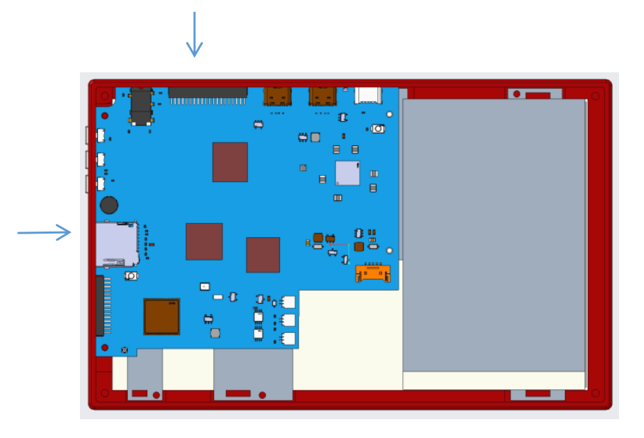
When installing the PCB, note the protruding part on the side indicated by the arrow in the diagram. Insert it in one direction first, then use the slight elasticity of the outer frame to hold it in place on the other side. This process is a bit difficult, and it's also quite difficult to remove it after installation. It's recommended to install the PCB first, then install the LCD screen. For easier disassembly and reassembly, you can enlarge the slot at the interface of the outer frame.
1.3 Routing
Here's a brief explanation of the routing design. To utilize the free prototyping voucher, a 4-layer board design was used. The main challenges were the A133 fan-out and DDR routing. The A133 package is a 0.5-pitch BGA, with a 3.5mil trace width and spacing for the fan-out. To facilitate routing, some pads were modified to elliptical shapes. DDR routing was done with 3W traces as much as possible. The closest free lamination structure is the 3313 structure, requiring a 6.16mil trace width for 50Ω impedance routing. I used 4mil, which resulted in an impedance deviation. The lamination sequence is signal layer-GND layer-VCC layer-signal layer, and the DDR routing area is signal-GND-signal-VCC. Pay attention to high-current voltage traces such as VCC-CPU and VCC-SYS; keep them as thick and short as possible, and use more vias at layer transitions. Before routing, it's best to find official hardware design guidelines or similar materials to help avoid pitfalls and ensure a successful first-time setup.

2. Software and Testing
This project requires no coding; simply burn the image file to use it. The initial design goal was to create a functional tablet that can also be used to learn Linux. The hardware includes a debug port and some peripheral GPIOs for expansion modules.
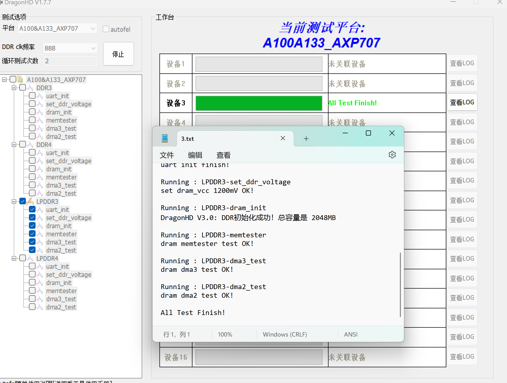
2.1 DDR Testing
After receiving the PCB board with some components soldered on, you can first perform DDR testing using DragonHD software. Connect it to the computer via USB OTG interface, open DragonHD, select A100&A133_AXP707, LPDDR3 frequency 888, click the start button, and then press the reset button on the board to begin testing.
2.2 Burning the Android Image
I used PhoenixCard software to burn the image file to the TF card for booting. The built-in eMMC is not yet used. Insert the TF card into the computer, open PhoenixCard, select the corresponding firmware, first click "Restore Card" to format the TF card, then select "Boot Card" and click "Burning Card".

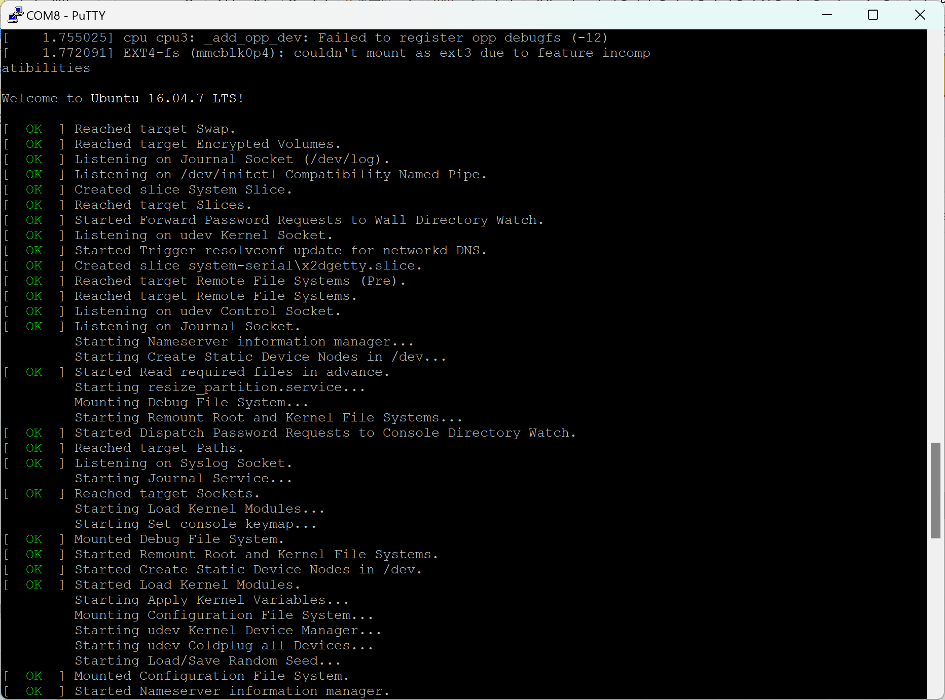
2.3 Serial Port Information
Viewing The board has JTAG and serial ports, which can be used for debugging and viewing information. The JTAG port is currently unused. The serial port pinout is shown in the figure below:

Set the baud rate to 115200 for communication. Due to size limitations, the interface uses a 1.27mm pitch connector. An adapter board is designed to convert it to a 2.54mm pitch connector for easier debugging and use. Through the serial port information, we can locate the problem. For example, previously, the system failed to boot. By checking the information, we found that the communication with the PMU was abnormal. I later discovered that the voltage of the PL port was selected to a power supply port with a default power of 1.8V, causing abnormal communication between the a133 and AXP707.

3. Assembling
the tablet structure is relatively simple. You can refer to the following installation method:
1. First, attach the middle layer to the outer frame, and then fix the PCB board to the middle layer.
2. Connect the FPC cable for the LCD screen, apply double-sided tape to the back of the LCD screen, and then snap it into the outer frame.
3. Connect and secure the battery, speaker, antenna, etc.
4. Replace the back cover and tighten the screws.

4. Specifications:
Tablet performance parameters are as follows:
Size: 173x109x15mm
; Screen: 7-inch, 1024x600 resolution;
Processor: Allwinner A133 quad-core Cortex A53;
Memory: 2GB LPDDR3;
Storage: 32GB eMMC, expandable with TF card;
Battery: 3.7V 3000mAh lithium battery;
Operating System: Android 10
; Wi-Fi: Dual-band Wi-Fi 6;
Bluetooth: BT5.2;
Audio Interface: 3.5mm headphone jack.
Data Interfaces: USB 2.0 x1, USB OTG x1
Charging Interface: Type-C
5. Usage and Other
Information: Usage
is similar to a regular tablet; long press the power button to turn it on and off. Currently, basic functions are implemented; APKs can be installed, and video and music playback work normally. One bug is that the speaker continues to play when headphones are plugged in. Checking the circuit, the headphone signal is detected normally, and the speaker amplifier chip's shutdown IO is not pulled low, suggesting a possible system mismatch. Additionally, the Wi-Fi signal is weak, possibly due to an incompatible antenna I purchased (I'm using an antenna from a previous 4G phone project).
Regarding finding documentation
: Some chip documentation is difficult to find online, unlike ST chips where a simple Baidu search will yield results. Here are a few methods:
1. Directly visit the official website and search for the corresponding chip model to see if there is any documentation. This is generally possible for chips like MCUs, which have user manuals, application manuals, datasheets, etc. However, companies like Allwinner don't have much documentation on their official websites.
2. Visit their relevant forums. Search for forums for the corresponding chip or company, log in, and look at other people's posts; some may provide information. For example, you can download Index (homepage) / WhyCan Forum (WowCool Developer Community).

3. Search for relevant projects on platforms like LCSC Open Source Platform. Many projects have corresponding shared materials in their attachments.
4. Join relevant QQ groups. Search for QQ groups with relevant project names or titles. After joining, you can find the materials you want in the file section.
5. If you really can't find anything, you can only use your money to buy a development board. There will definitely be a lot of materials included. Moreover, you can use the development board to verify in the early stages. If you have enough money, I suggest buying a development board. It can save a lot of time by referring to it.
Conclusion
This is my first Linux project. I am grateful to LCSC Open Source Platform for providing the opportunity. I also thank @logicworld for writing the "Introduction to ARM High-Speed Circuit Design from Zero" series of articles on LCSC Open Source Platform. I have benefited a lot. Most importantly, it reminded me that there was a problem with the DDR schematic package in LCSC's shared library, which prevented me from making a mistake on my first board. I recommend that those who want to get started read it. I also bought Wei Dongshan's Linux development board before, but it has been gathering dust. I hope to learn something new through this project. If you're interested, feel free to leave a comment. If there's enough interest, we can create a QQ group for discussion. I'm a complete beginner in Linux, and I'd love to learn and grow together with everyone.


 京公网安备 11010802033920号

 06161010


