For performance parameters, refer to the LT4320 datasheet.
PDF_LT4320 Ideal Rectifier Bridge.zip
Altium_LT4320 Ideal Rectifier Bridge.zip
PADS_LT4320 Ideal Rectifier Bridge.zip
BOM_LT4320 Ideal Rectifier Bridge.xlsx
95909
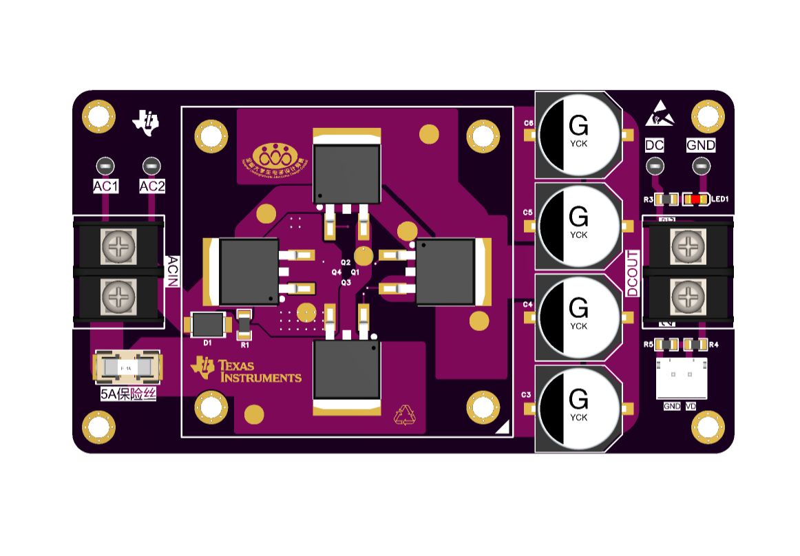
240118_Adjustable Power Supply Based on XL6019 and XL4015 V2.0_Open Source
Adjustable power supply based on XL6019 and XL4015 V2.0
Hey everyone! This time, I'm presenting a topology version of the previous open-source project – "240131_Adjustable Power Supply V1.0 Based on XL6019 and XL4015_Open Source".
(Note: Strictly speaking, the power distribution board in this version is a failure, so this project can only be provided as an idea. The reason will be explained later.)
I still recommend using a +11.1V model aircraft battery for the power input. Unlike the previous version, the following modifications were made to the power supply's size and practicality:
1. The power supply structure was changed
from a single 85*80cm board to a dual-board design: an 80*37cm boost/buck board and an 84*53cm power distribution board. This reduced the floor space while increasing the functional area. The combined size of the two boards is 84*53*34cm.
2. The boost/buck board
was changed from two boost channels and two buck channels on a single board to a single buck and single boost channel on a single board.
Heat dissipation vias were added, and the entire bottom layer is covered with copper to enhance heat dissipation.
The distance between the boost/buck board and the power distribution board was increased to allow for the height of other components on the power distribution board (not included in the cover version).
3. The power distribution board
has a socket for inserting two boost/buck boards.
Reverse connection/soft start protection, overvoltage protection, and surge protection circuits were added.
One current detection circuit and two voltage detection circuits were added.
4. Issues in this project:
Regarding the
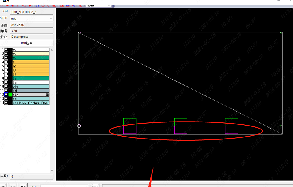

boost/buck board:
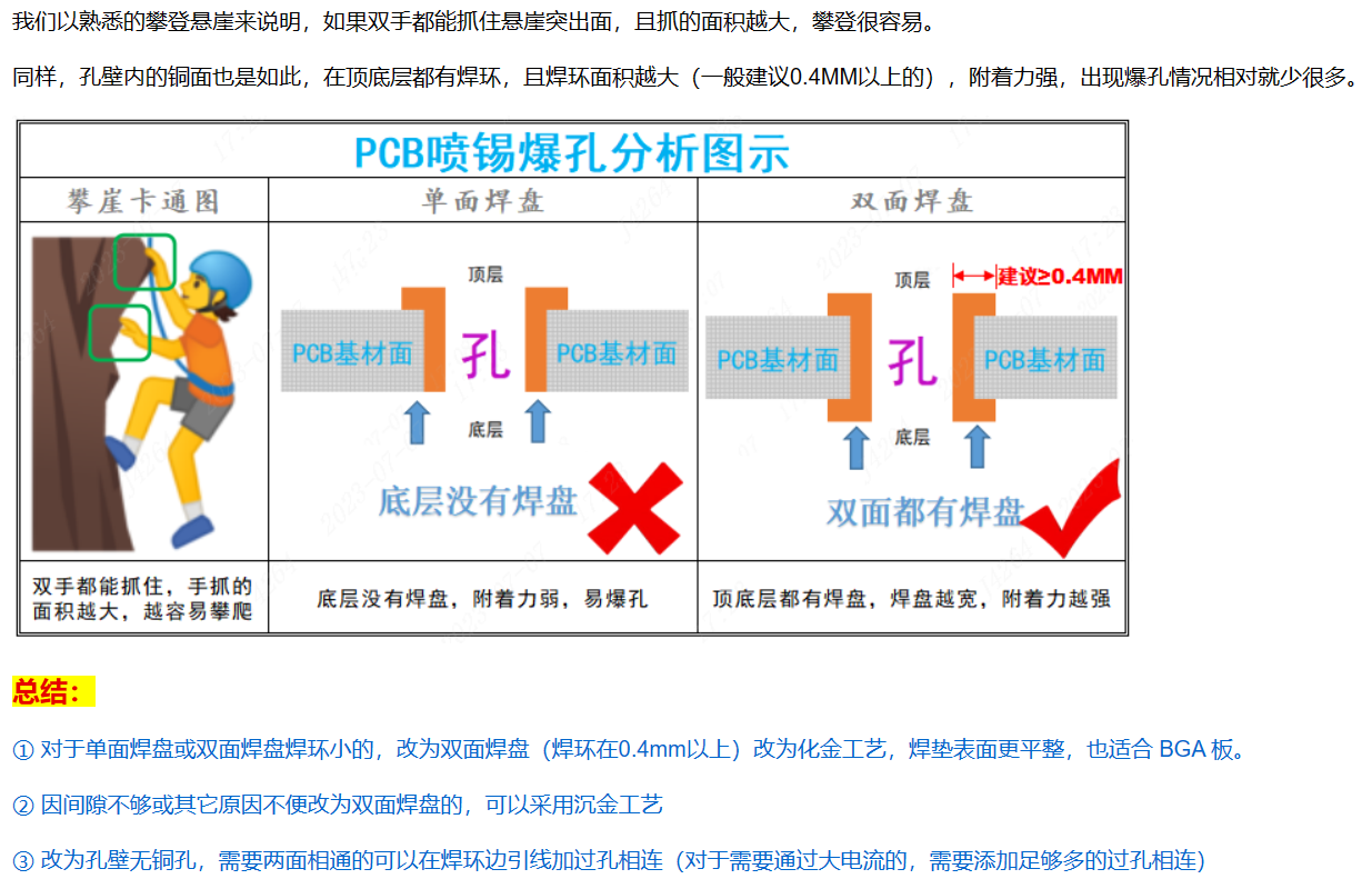
There is a risk of PCB defects.
PDF_240118_Adjustable Power Supply Based on XL6019 and XL4015 V2.0_Open Source.zip
Altium_240118_Adjustable Power Supply Based on XL6019 and XL4015 V2.0_Open Source.zip
PADS_240118_Adjustable Power Supply Based on XL6019 and XL4015 V2.0_Open Source.zip
BOM_240118_Adjustable Power Supply Based on XL6019 and XL4015 V2.0_Open Source.xlsx
95910
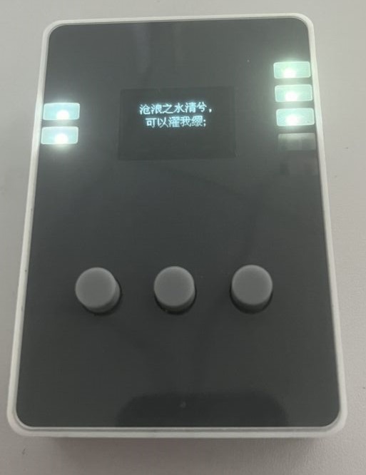
Calendar/Weather Ornament
A minimalist calendar widget based on the ESP32-C3 module, featuring three main interfaces that switch between each other: calendar, clock, and current weather. It includes web-based network configuration, displays classical Chinese poems upon startup, and automatically hides the weather information when the network is disconnected.
Basic functions:
Time display,
current weather display![IMG_3200.JPG]

, display today's day of the week (essential for working people),
display date (which day)![IMG_3199.JPG]
, startup logo, display ancient Chinese poems![IMG_3191.JPG],
today's horoscope (not displayed)
, answer book (not displayed).
ESP32-C3_Calendar.7z
IMG_3200.JPG
IMG_3201.JPG
IMG_3202.JPG
IMG_3199.JPG
PDF_Calendar-Weather Ornament.zip
Altium_Calendar_Weather Ornament.zip
PADS_Calendar_Weather Ornament.zip
BOM_Calendar_Weather Decor.xlsx
95911
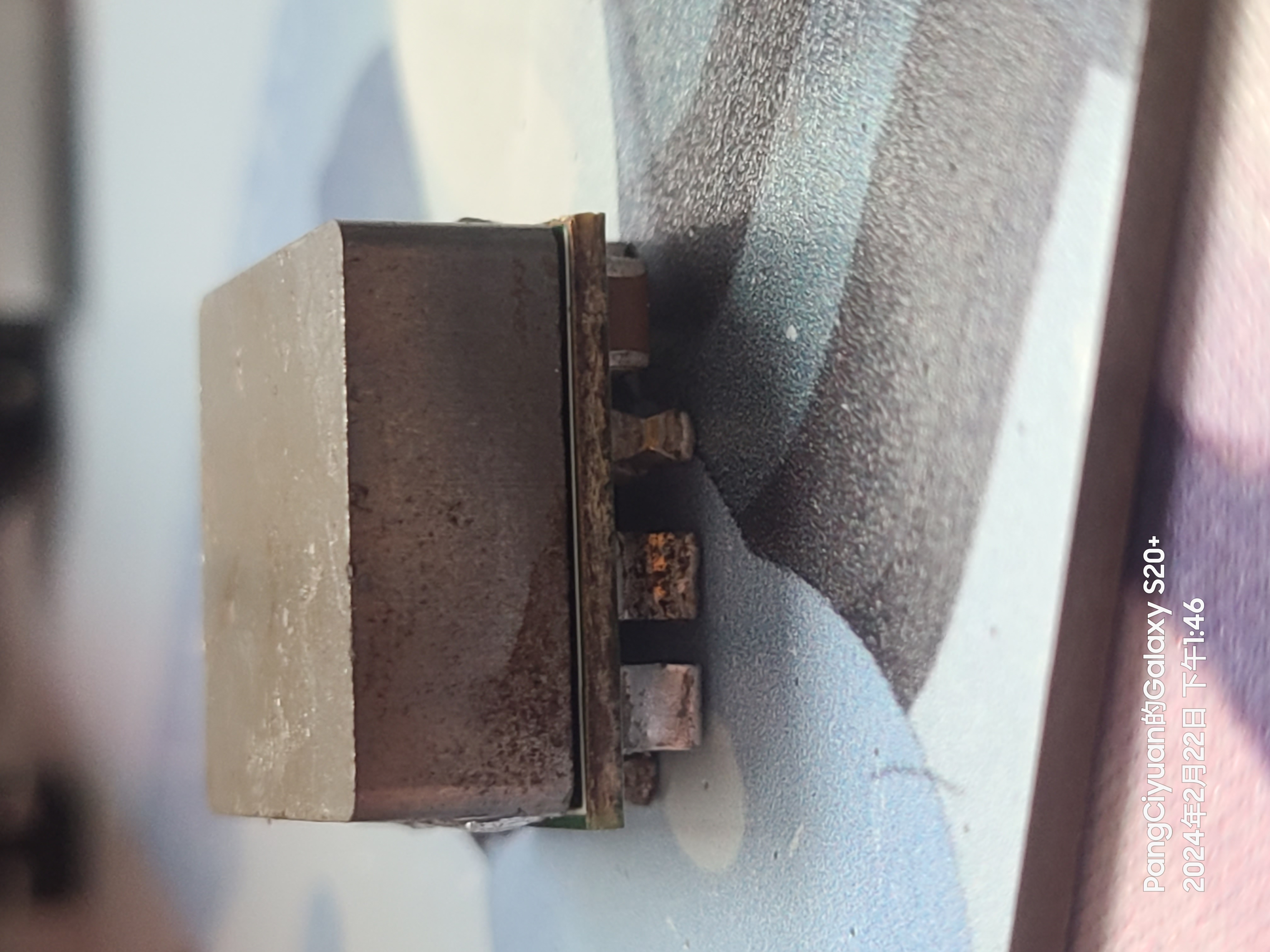
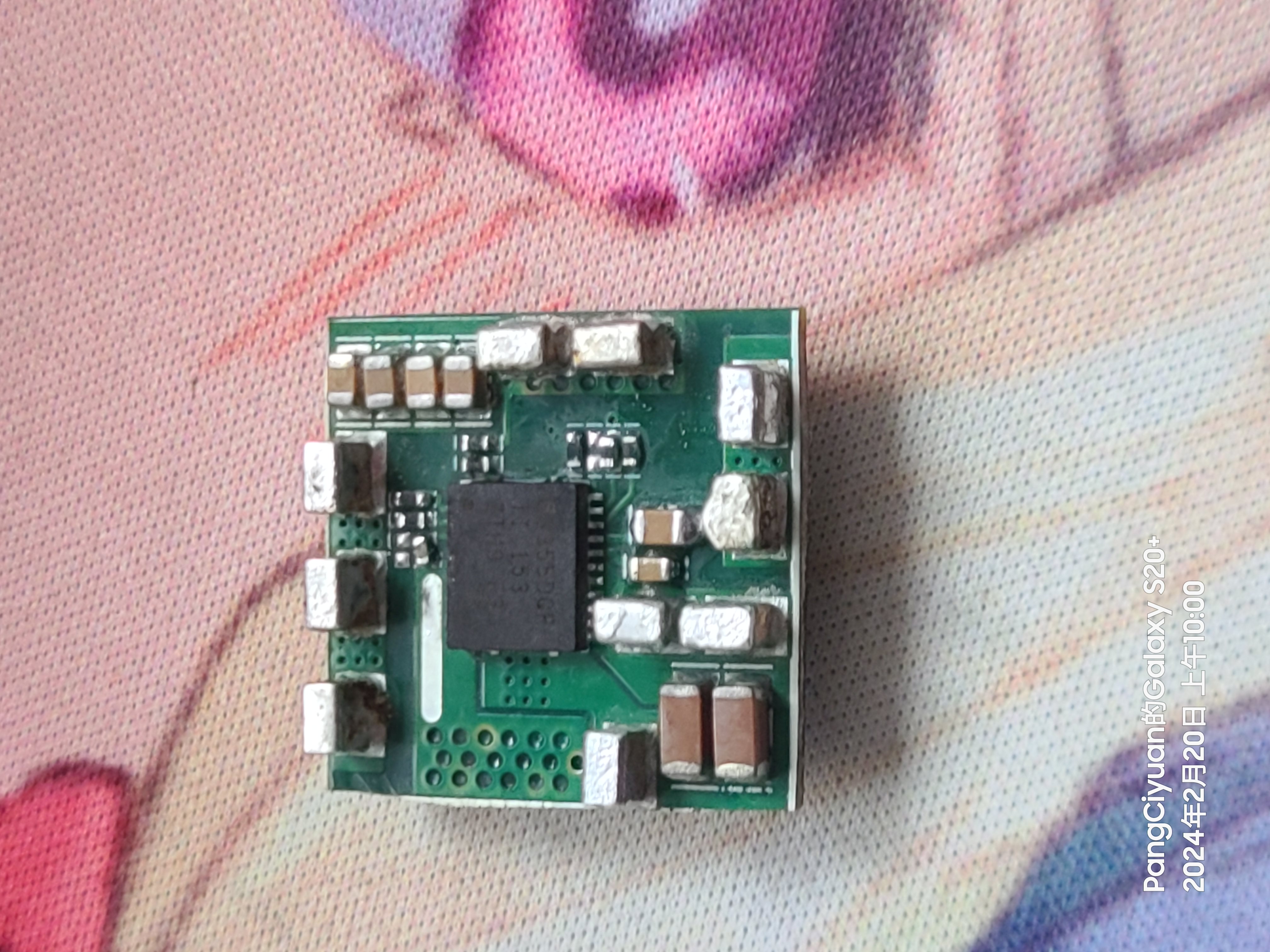
TPS53355 30A Step-Down DC-DC
The 30A output buck module
features high efficiency under light load
with a switching frequency of up to 1MHz.
Input voltage 7-14V,
output 0.6-5.5V.
Passive cooling only provides 40W output, forced air cooling can provide 140W output.
The circuit board is drawn backwards (modifications
have been made to reserve the mode switching and switching frequency resistor positions; please refer to the schematic for configuration).
External input/output capacitors must not be less than 200uf.
The schematic's BOM list is not reliable; please refer to the PCB's BOM list.
tps53355_231121_195925.pdf
PDF_tps53355 30A Step-Down DC-DC.zip
Altium_tps53355 30A step-down DC-DC converter.zip
PADS_tps53355 30A step-down DC-DC converter.zip
BOM_tps53355 30A step-down DC-DC converter.xlsx
95913
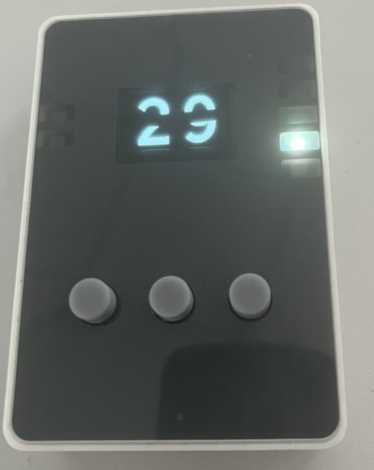
ESP8285 Relay Controller V2.0
The WIFI relay developed based on ESP8285 uses the MQTT communication protocol. The protocol content can be customized, and the MQTT server address and user can be configured by logging into the device's web management backend.
1. Equipment Description
1.1 Appearance
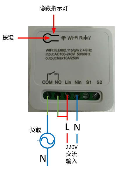
1.2 Power Supply:
100~240V AC input, Lin connects to the live wire, Nin connects to the neutral wire.
1.3 Load Connection:
The output signal is a passive relay signal, used for signal on/off control. It can handle a maximum load current of 10A. COM is the relay common terminal, NO is the relay normally open terminal, and the default state upon power-on is off.
1.4 Indicator Light Status Description:
There are three LED indicators: red, green, and blue. The corresponding device states are as follows:
Red light flashing rapidly: Waiting for network configuration Red light flashing slowly: Connected to the router, connecting to the MQTT server; Red light on: Connected to the MQTT server;
Blue light flashing once: Button pressed for more than 5 seconds;
Green light on: Relay on;
Green light off: Relay off.
1.5 Button Operation
: Short press for 1 second and release: Switch relay state;
Long press for 5 seconds: Device enters network configuration mode.
2. Function Operation
2.1 Connecting to the Wi-Fi router
requires using a mobile phone to run network configuration software. First, install the esptouch software on your phone. It only supports Android systems. Software download link: https://github.com/EspressifApp/EsptouchForAndroid/releases/tag/v2.0.0/esptouch-v2.0.0.apk
The network configuration steps are as follows:
Power on the device;
Press and hold the button for 5 seconds (release after the blue light flashes rapidly). At this time, the device enters network configuration mode;
Connect the phone to the router;
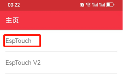
Launch the esptouch software on the phone and select EspTouch;
Enter the router password in the password box and then click confirm;
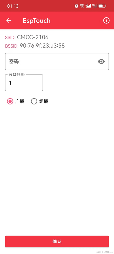
After successful network configuration, the EspTouch software will display the device's BSSID (MAC) and the LAN IP address assigned to the device by the router. You need to record the IP address for logging into the device's web management backend.

2.2 Web Management Backend
2.2.1 Login
Launch a mobile phone or computer browser on the same local area network. Enter the current device's IP address in the address bar, such as 192.168.10.103, and click to enter:

Username: admin
Default password: 123456
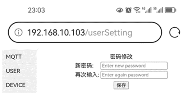
2.2.2 Change login password
Select the "USER" option in the directory bar:
2.2.3 Configure MQTT server
Select the "MQTT" option in the directory bar:

The default server HOST: broker.emqx.io, port: 1883, is a free MQTT server that can be used for testing.
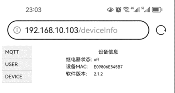
2.2.4 View device information
Select the "DEVICE" option in the directory bar:
3. Detailed explanation: http://t.csdnimg.cn/uOjTC
WIFI Relay Communication Protocol - Official Version V1.5.pdf
Demo video.mp4
Source code link.txt
PDF_ESP8285 Relay Controller V2.0.zip
Altium_ESP8285 Relay Controller V2.0.zip
PADS_ESP8285 Relay Controller V2.0.zip
BOM_ESP8285 Relay Controller V2.0.xlsx
95914
electronic


 京公网安备 11010802033920号

 NCV7701


