I. Design Functions:
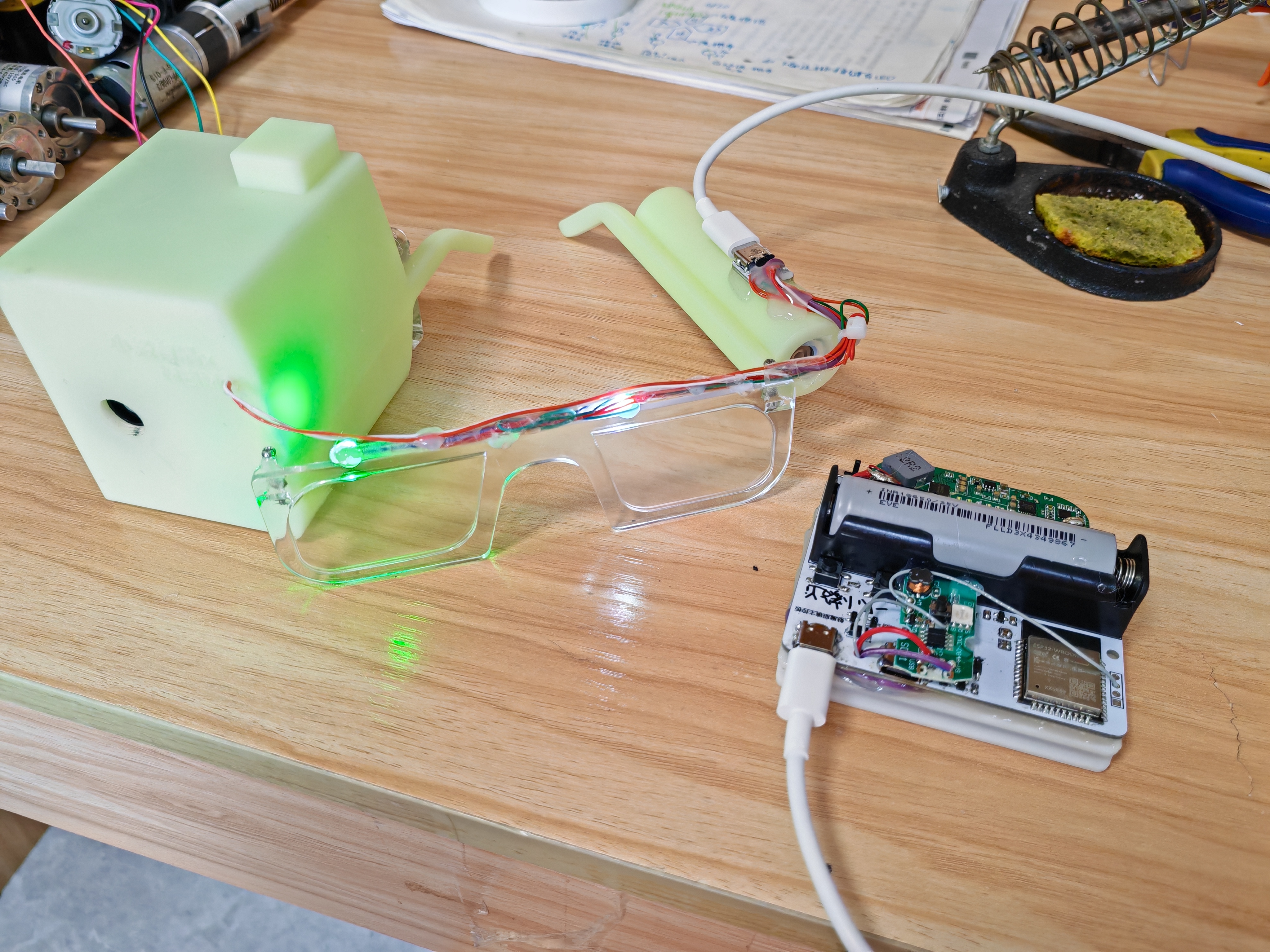
A magical pair of glasses with features including RGB lights on the lenses for displaying changing lighting effects, a bubble machine on the left frame for blowing colored bubbles, and a humidifier module on the right frame for creating a smoky atmosphere. Suitable for pranks and creating a lively atmosphere at parties. All functions can be controlled via a mobile app or a button. II. Structure:
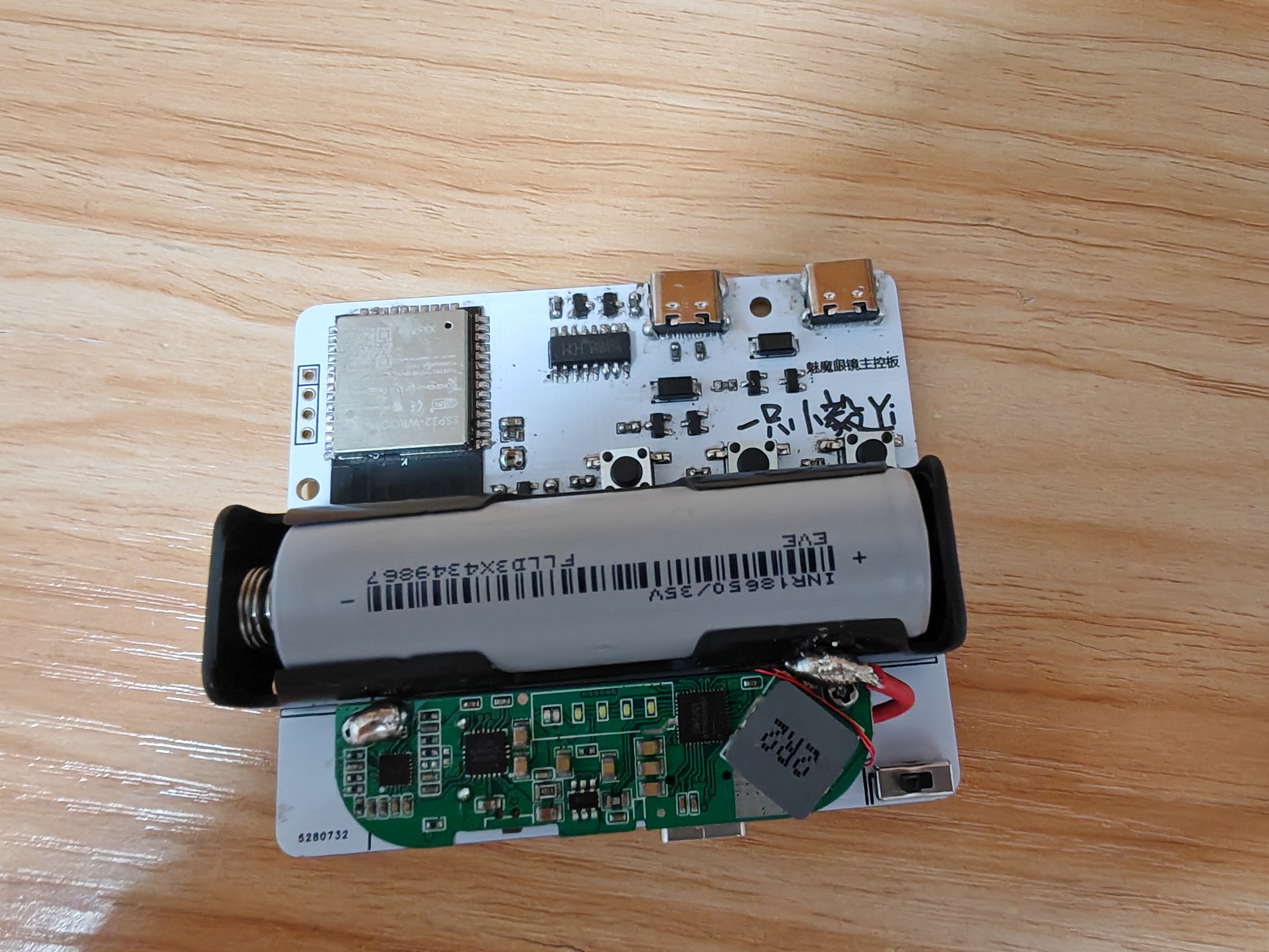
The glasses themselves, along with a motherboard and battery box hanging on the back of the neck, are connected via a double-ended Type-C cable (proprietary protocol).
The glasses integrate two RGB lights, an ultrasonic atomizing plate with corresponding cotton swabs, a bubble machine, and a corresponding bubble solution bottle. An adapter board inside the glasses converts the cables of these devices to Type-C for easy connection to the main control box
. The box contains the circuitry and battery; the left Type-C port is used for uploading programs, the right Type-C port connects to the glasses, and the bottom Type-C port is used for charging (supports reverse charging as a power bank).
Materials used:
Bubble machine (core removed from disassembly). https://detail.tmall.com/item.htm?id=701462940556&spm= a1z09.12.0.0.11ca2e8dny0jW0&_u=j20c6g5s2te348
Humidifier (Core removed after disassembly) https://detail.tmall.com/item.htm?id=733374679653&spm=a1z09.12.0.0.11ca2e8dny0jW0&_u=j20c6g5s2t1d04
Power Bank Motherboard https://item.taobao.com/item.htm?spm=a1z09.12.0.0.11ca2e8dny0jW0&id=701513981873&_u=j20c6g5s2t54e6
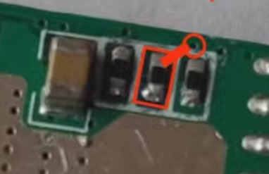
(The resistor on the back needs to be changed to 10k.)
See the attached 3D printing file. Below is the assembly diagram: the bubble machine is installed on the left temple, and the spray module is installed on the right temple (left and right directions shown in the diagram). The humidifier is filled to hold the spray cotton strips.

III. Circuit details
are in the editor below. The actual circuit board diagram is shown below.
IV. Code:
See the attached ESP32 code (all.ino).
You need to download "Bluetooth Serial Port SPP" (attached base.apk) on your phone first, and then follow the instructions in the attached video.
V. Finished Product
3D Printing Files.zip
APP Setup Tutorial.mp4
All.ino
base.apk
Demo video (2).mp4
PDF_DIY Succubus Glasses.zip
Altium_DIY Succubus Glasses.zip
PADS_DIY Succubus Glasses.zip
91238
ECHO Heated Stand (V2)
The ECHO heating stage V2 version combines domestically produced STC microcontrollers with domestically produced EDA design software, a powerful collaboration!
Update Log
2024/06/28
Released ECHO Heating Platform V2
Precautions
: After setting up the ECHO heating platform:
Activate and set
the power. Clean
the heating plate
. Heat at approximately 220℃ for 1 minute to oxidize the aluminum substrate surface.
After completing the above steps, the heating plate will have very little solder adhesion.
Optimal operating temperature: 100-240℃, short-term operation at 300℃ is fine. Due to the insulation material of the aluminum substrate, excessively high temperatures will produce harmful gases and cause irreversible damage! Open Source
License
This project uses the CC-BY-NC-SA 3.0 open source license, i.e., Creative Commons Attribution-NonCommercial-ShareAlike.
CC: Creative Commons License
BY: Attribution, you must give appropriate attribution, provide a link to this license, and indicate whether modifications were made (to the original work).
SA: ShareAlike, if you remix, transform, or build upon this work, you must share your contributions under the same license as the original.
NC: NonCommercial, you may not use this work for commercial purposes. The ECHO heating platform V2 uses an STC8H8K64U microcontroller with built
-
in USB functionality, powered by a CH224K decoy chip, and supports PD3.0/2.0 protocols. The screen is a 0.96-inch TFT LCD display with a 45° angled display. The heating plate is made of aluminum (in three versions: H34/H50/H100), and the outer shell is 3D printed (PLA or FDM). The controller and heating plate are pluggable, facilitating the use of different heating platform models.
The domestically produced STC8H8K64U chip
features built-in USB hardware, supporting software updates
. The Type-C power interface supports PD3.0/2.0 protocols.
A 0.96-inch TFT color LCD screen
with a 45° angled display makes data viewing more convenient
. A front-mounted dial switch facilitates one-handed operation.
Three operating modes are available: constant temperature mode, curve mode, and reflux mode.
The controller and heating platform have a plug-in design, supporting the replacement of heating plates of different areas. The outer
shell can be printed using photopolymer 3D printing. Different colors and materials can be selected
using JLCPCB 3D printing.
The ECHO control board is designed as a double-layer board, allowing users to utilize JLCPCB's newly upgraded immersion gold process.
Operation instructions:
The buttons have three positions: upper, middle, and lower.
The upper and lower buttons default to an increase/decrease principle.
The middle button is the function button.
1) On the main interface, click the function button to control heating on/off. When the main interface is in constant temperature mode, double-clicking the function button switches the display between power and internal resistance.
2) On the main interface, long-press the function button to enter the settings menu.
3) In the settings menu, you can select five settings items: PID settings, parameter settings, mode settings, power settings, and basic settings by clicking the up and down buttons.
4) In the settings menu, click the function button to enter the corresponding first-level menu.
5) In the first-level menu, click the function button, select the item to be adjusted, and adjust the corresponding data using the up/down buttons. Long press the function button to return to the first-level menu.
6) In the first-level menu, long press the function button to return to the settings menu, and long press the function button again to return to the main interface.
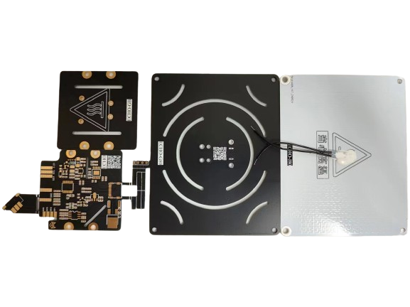
The
ECHO34 requires printing four PCB files: ECHO-Control Board, ECHO-Cover, ECHO-J34, and ECHO-G34.

Figure 1. PCBs required for ECHO34. The
ECHO50 requires printing four PCB files: ECHO-Control Board, ECHO-Cover, ECHO-J50, and ECHO-G50.
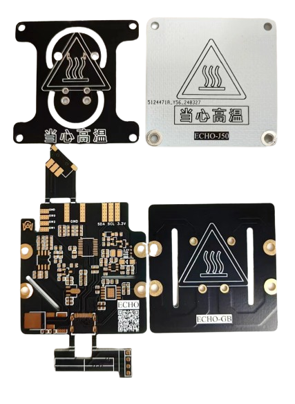
Figure 2. PCBs required for ECHO50 .
The PCBs required for ECHO100 (not yet open source).
ECHO-J34 and ECHO-G34 are combined to form the H34 heater.
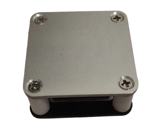
Figure 3. The H34 heater
ECHO-J50 and ECHO-G50 are combined to form the H50 heater.

Figure 4. The H50 heater
ECHO-control board and ECHO-cover plate are combined to form the controller.
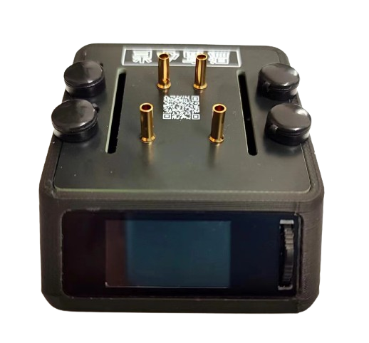
Figure 5. The controller
can be combined with the H34 heater/H50 heater/H100 heater to form ECHO34/ECHO50/ECHO100 respectively.
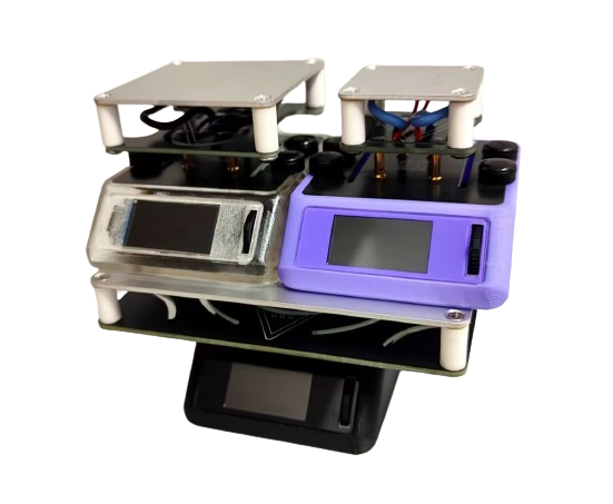

Figure 6. ECHO Whole Box
Soldering and Assembly Tutorial
I. Soldering
Tutorial Refer to the first-generation soldering tutorial for the soldering tutorial.
ECHO - Control Board Soldering: [Part 1] [Control Board Soldering]
ECHO - Controller Assembly: [Part 2] [Controller Assembly]
ECHO - Heating Plate and Temperature Sensor Assembly: [Part 3] [Heating Plate and Temperature Sensor Assembly]
ECHO - Heater Assembly [Part 1]: [Part 4 (Part 1)] [Heater Assembly]
ECHO - Heater Assembly [Part 2]: [Part 4 (Part 2)] [Heater Assembly]
ECHO Heating Table V2 Version Explanation Video: ECHO Heating Table V2 Version Explanation Video
Soldering Precautions
Online soldering auxiliary tools are in the attachment:


The above picture is a physical soldering diagram. There are three points to note:
Do not solder the C75K capacitor
. Do not solder R32
. Solder R37 and R38 as shown in the diagram.
Solder the 8P base of the screen to the corresponding 8P screen. 13P is for soldering the screen.
II. Program Download Tutorial
Ensure correct soldering before proceeding!
Open the STC-ISP software on your computer, plug in the Type-C data cable,
press and hold the ECHO heating station function button, and quickly insert the Type-C data cable's C port into the ECHO heating station's C port
. If the soldering is completely correct, the STC-ISP software will display "STC-USB Writer (HID1)," as shown in Figure 7.
If the hardware is not correctly identified, repeat steps b and c until it is correctly identified

(Figure 7).
After successful hardware identification, perform the following operations (Figure 8):
Chip model selection: STC8H8K64U;
IRC frequency: 24MHz
; EEPROM size: 0.5K;
Open program file: ECHO-V2-20240628.hex
(Download
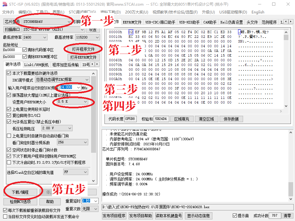
Figure 8). Software configuration:
Before downloading the program, abnormal voltage inducement is normal. Test the 3.3V output voltage using a standard 5V power supply.
After downloading the program, the screen should display correctly. If not, check it yourself.
Welcome to join our group for discussion.
Communication methods
: Bilibili: a1298703610
; QQ group: 902453827.
Acknowledgements:
Thanks to STC and JLCPCB for their support! Thanks to Along for providing the activation code!
ECHO-V2-2024-6-28.html
ECHO Heating Station V2 Instruction Manual.pdf
BOM_Board1_PCB1_2024-06-28.xlsx
ECHOV2-V1.1.stl
ECHO-V2-20240628.hex
PDF_ECHO Heating Platform (V2).zip
Altium_ECHO Heating Table (V2).zip
PADS_ECHO Heating Table (V2).zip
91239
LCSC*Liangshanpai Portable Multifunctional Oscilloscope/Instrument
Participate in the LCSC Oscilloscope Advanced Training Camp and use the LCSC Liangshanpai development board and its accompanying 4.3-inch touchscreen portable multi-functional instrument, which has functions such as oscilloscope, signal generator, and serial port data viewer.
Project Introduction
This project is a portable multi-functional instrument designed based on the Liangshanpai development board and the matching 4.3-inch RGB touch screen priced at 98 yuan. It has functions such as dual-channel oscilloscope, signal generator, and serial port data viewer. The 148 yuan version will also be open source after the subsequent program is adapted.
The specific usage video has been released on Bilibili. Welcome to watch: [Click to jump to Bilibili physical demonstration video!]
1. The overall system block diagram is as follows:

Some contents of this project refer to the official case of Liangshanpai oscilloscope [oscilloscope expansion board], and supplement and improve it in many aspects to realize the functions of rechargeable portability, dual-channel signal acquisition, 4.3-inch large screen, full touch human-computer interaction, serial port signal viewing (supports Chinese characters) etc.
2. The performance parameters are as follows:
(1) Oscilloscope
① Supports dual-channel maximum ±10V peak-to-peak signal input, sampling rate of 2MSPS, and the measured waveform can be displayed stably.
② Supports one-key Auto function, which automatically adjusts the waveform to the appropriate display conditions.
③ It has a trigger function, which can realize the adjustment of waveform vertical offset, horizontal offset, trigger threshold, etc.
(2) Signal generator
① Supports the output of five waveforms: sine wave, square wave, triangle wave, positive sawtooth wave, and anti-sawtooth wave.
② The output frequency supports continuous adjustment in 1KHZ-50KHZ.
③ The output peak-to-peak value supports continuous adjustment in 0.1V-2.5V.
(3) Serial port data viewer
① Supports adjustment of multiple baud rates.
② Supports text display, HEX data display, and waveform analysis display functions.
③ Supports receiving and displaying any Chinese characters.
Hardware circuit design
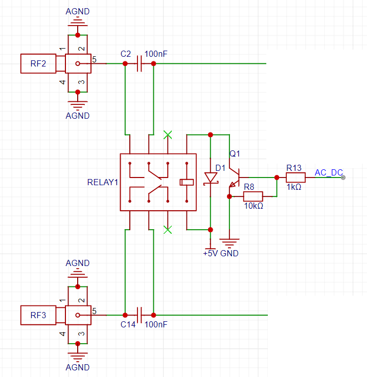
1. Signal coupling circuit
The microcontroller controls the corresponding GPIO high and low levels, thereby controlling the solid-state relay to realize AC/DC coupling of the input signal.
2. Analog Front-End Circuit:
The analog front-end circuit is based on the official case study of the Liangshanpai oscilloscope expansion board. For details, please refer to: [Oscilloscope Expansion Board]
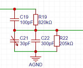
Signal Attenuation Circuit:
Signal Gain Processing and Vertical Shift Circuit:
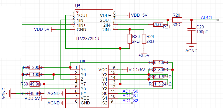
Signal Generator Circuit.
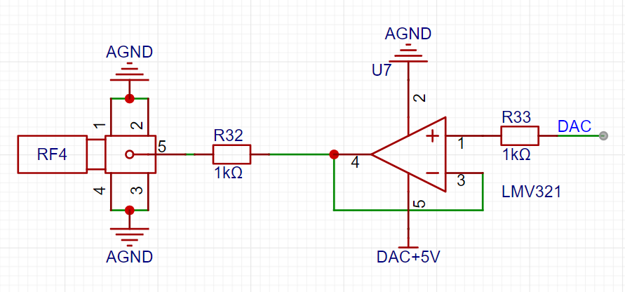
3. Power Supply Circuit
: An SGM3204 charge pump generates -5V to power the dual power supply of the operational amplifier.


A CJ431 generates 2.5V as the reference voltage for the microcontroller's ADC. Note that the default reference voltage for the Liangshanpai ADC is 3.3V. Therefore, it is absolutely essential to remove the 0-ohm jumper resistor for the corresponding A3.3V AGND on the Liangshanpai; otherwise, the measured data will be incorrect, and the circuit may even be damaged.


An ME2159AM6G is used to boost the lithium battery voltage to 5V.

The lithium battery charging management uses an LP4056HSPF. During charging, an LED will light up to indicate that charging is in progress; the LED will turn off when charging is complete. Due to space constraints, this project uses a 3mm thick, 50mm*60mm 1200mAh lithium battery to power the entire system. Hot melt adhesive is used to install it between the PCB and the RGB screen.
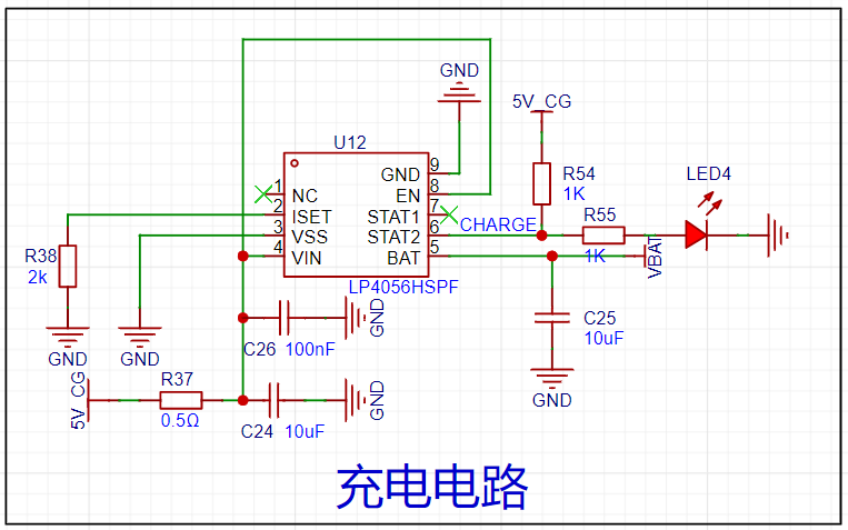
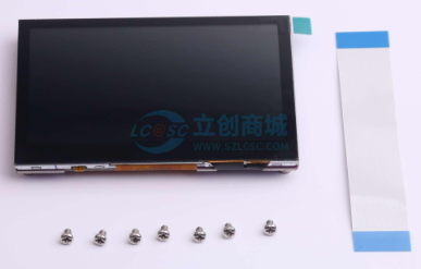
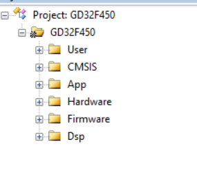
( See Taobao shopping cart link: 77₤WEYTWPyGCsC₤ https://m.tb.cn/h.5uFXj1X CZ3460) I've shared some awesome content with you, come check it out! 4. RGB Screen: This project uses the 4.3-inch RGB screen that comes with the LCSC development board, with an 800*480 pixel resolution, providing a detailed display. Since the LCSC board has a built-in RGB interface, the hardware circuitry does not need to be designed separately. Purchase Link: https://item.szlcsc.com/8351841.html?t=1708862395529&s=1708862395529 5. PCB Design Instructions: Because the width of the 4.3-inch RGB screen exceeds 10cm, the width of the board outline will be shortened to within 10cm to ensure free prototyping. This project's PCB uses a double-layer PCB layout, employing two ground planes, AGND and GND, which are connected by a 0-ohm resistor. LED4 is a charging indicator light, placed near the edge of the board outline. When charging is initiated, the LED lights up; when charging is complete, the LED turns off. Simultaneously, when the board is powered on, charging details can be viewed on the battery icon at the top of the screen. The PCB physical image and interface function descriptions are as follows . A base plate dimension drawing is provided in another PCB file. An acrylic base plate can be customized, and copper pillars can be used to fix it to the back for protection. Function Usage Instructions: 1. Oscilloscope Function Description: The overall UI interface is shown in the figure. All human-computer interaction uses a touch screen, making operation more convenient. Note that the noise level of the sine wave shown in this image is quite high. This is because the entire system was powered by a computer's USB port, and the ripple from the USB power supply is likely large, causing some jitter in the data converted by the ADC. However, this phenomenon is much better when powered by a lithium battery! Observing the UI interface, the top left corner displays the battery level; next is the AUTO button. When the waveform display density is too dense or too sparse, pressing the AUTO button will automatically adjust the ADC sampling rate and vertical voltage gain to adjust the waveform to a suitable display state; the MEASURE button displays the signal acquisition from two channels in a small window; the RUN button starts or pauses sampling; the FFT button displays the spectrum (amplitude spectrum) of the Fast Fourier Transform for the current channel; the UART button switches the serial data viewer interface; pressing the OUT button displays the signal generator window, where the output signal type, frequency, and peak-to-peak value can be adjusted; the right side of the screen has buttons for adjusting the oscilloscope signal acquisition parameters; the two sliders on the left and right can adjust the vertical offset and trigger threshold of the waveform respectively; finally, there is a rotation button in the lower left corner, which rotates the screen. 2. Serial Port Data Viewer Function Description: I have integrated the functions of a serial port assistant from a computer into this instrument. It allows adjustment of the baud rate and different data parsing and display modes, making the serial port assistant portable. In character mode, in addition to receiving ASCII characters, it also receives and displays arbitrary Chinese characters; HEX mode displays received data in hexadecimal format; in waveform mode, the transmitter sends frames in the format "x,x,x,x", which this instrument can parse into waveforms, supporting up to six channels of floating-point waveform parsing (theoretically ten channels are also possible, but the final result may have bugs, as ten channels of data would result in a very long serial port data). An attached Python program generates six sine wave strings and sends them to the serial port, which can be used to test the waveform mode of the serial port data viewer. Software Code Description: 1. Project Structure : The App folder contains oscilloscope function code files, serial port data viewer function code files, and signal generator function code files. The Hardware folder contains various driver files. 2. Parameters


The OSC.h and Wave_out.h files define relevant structures that encompass almost all modifiable parameters of the oscilloscope.
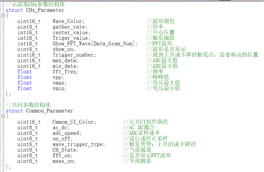
The Init_Oscilloscope function allows for convenient initialization of parameters such as sampling channel waveform color, initial sampling rate, initial signal gain, and AC_DC.
3. Screen Touch Control:
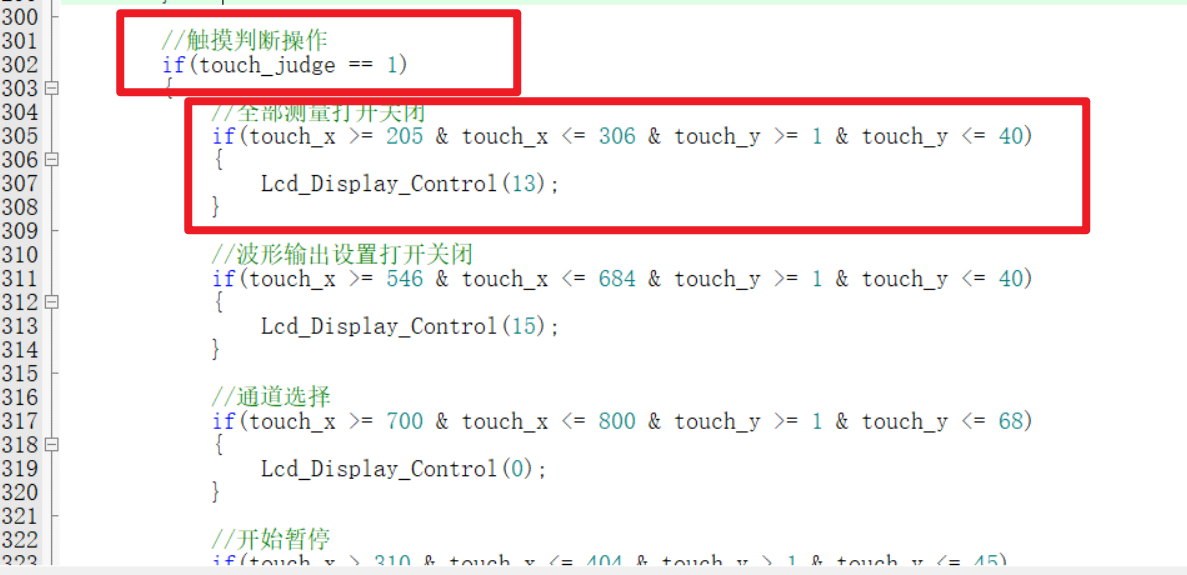
The 4.3-inch screen used in this project supports up to 5-point simultaneous touch, but for ease of control, this project only supports single-point touch. As shown in the program below, when the touch_judge variable equals 1, it indicates that the screen has been pressed. Then, touch_x and touch_y are used to determine the area pressed, finally identifying the pressed position and executing the corresponding function. Based on the different touch priorities of each button, the touch position determination is placed in the timer interrupt service function and the corresponding function. Due to my limited experience, I feel this method is somewhat inefficient (or perhaps requires LVGL?). I welcome expert advice and suggestions for simpler and more convenient coding methods.
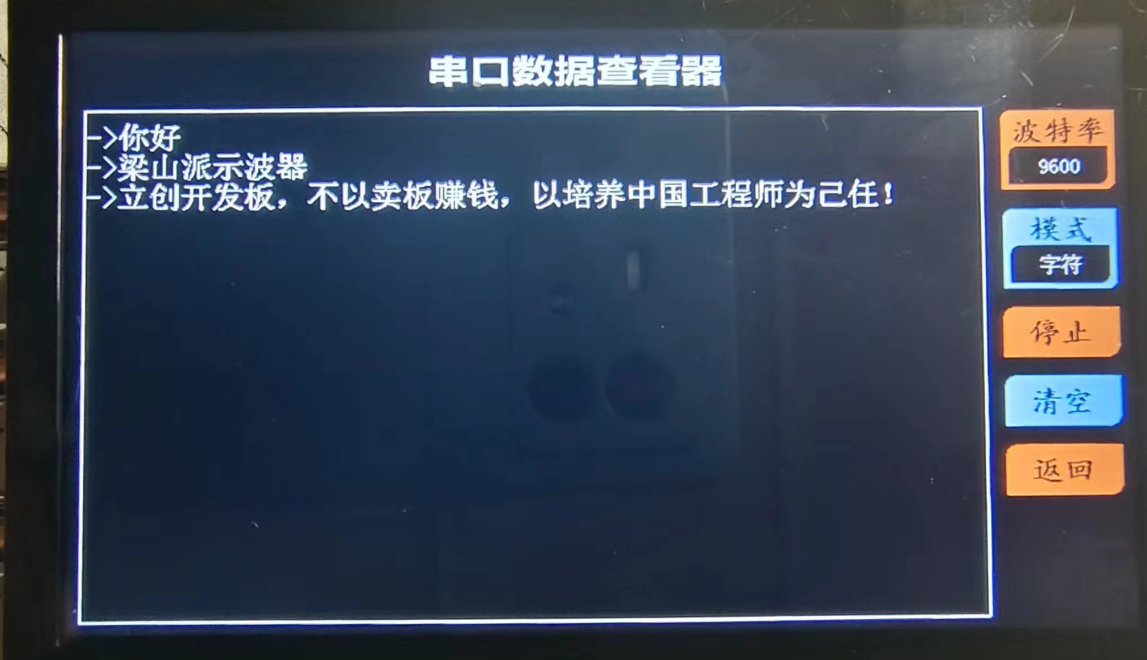
4. The method for receiving and displaying Chinese data in the serial port data viewer
is more in line with language habits. Since we sometimes use Chinese for serial port data debugging, this project saves the font information to the SPI_Flash on the Liangshanpai board, adding the function of receiving and displaying Chinese serial port data. It has functions such as baud rate adjustment, data parsing mode adjustment, start/stop monitoring data, and clear window. The Chinese display is shown in the figure below.

The steps for flashing the font into the SPI_Flash are simple. Just prepare a 16G or 32G TF card (other capacities haven't been tested, so I don't know if they will work), insert it into a card reader and connect it to the computer. Create a folder named FONT in the root directory of the TF card, decompress the font file (provided in the attachment) and store it there. Then insert the TF card into the TF card slot of the Liangshanpai board, flash the Chinese font flashing program in the attachment, and reset. Next, use a serial port assistant on the computer to monitor the real-time status of the font library writing process. The whole process takes about one or two minutes. When you receive "FLASH font_init success!", the font library writing is complete, and the serial port data viewer can then receive and display Chinese data!

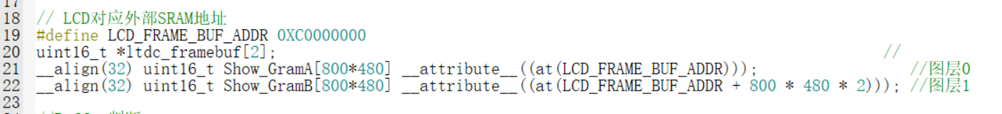
5. Screen Refresh
This project uses EXMC to refresh screen data. After initializing the screen display parameters, simply modifying the screen cache data stored in the external SDRAM will automatically refresh the screen data. Users do not need to manually refresh, which is very convenient, and the display frame rate is also very high. The Liangshanpai has a built-in RGB FPC interface, which can be connected to the screen's RGB interface using a ribbon cable, which is also very convenient.
Since the waveform and some components need to be superimposed on the grid, if the screen display function is called immediately every time the screen display content is changed, the waveform will flicker. Why is this? If you refresh the waveform grid (raster) to the screen first, and then refresh the waveform itself, the previously displayed waveform will be overwritten during the grid refresh process. This will cause a brief period where the waveform is not displayed on the screen. Then, when the waveform is refreshed again, it reappears. This intermittent display of the waveform creates a flickering effect. To address this, a dual-buffering approach is used: Buffer 1 is used for screen refresh, and Buffer 2 is used for temporary pixel data modifications. When an update is needed, Buffer 2 is moved to Buffer 1. However, this is a rather crude approach, using direct copying. This has obvious drawbacks: it blocks CPU operation (on an 800*480 screen), reducing efficiency. Therefore, I welcome suggestions from experts on more efficient display methods (such as alternating between the two buffers for screen display; I tried this, but it didn't work, so frustrating!).

Finally
, I would like to express my sincere gratitude to JLCPCB for providing such a great platform, which has significantly lowered the barrier to entry for electronic design, allowing more people's creative ideas to be transformed into tangible products. "Not making money by selling boards, but taking the cultivation of Chinese engineers as our mission" is LCSC's motto for its development boards. LCSC is not only saying this, but also constantly putting it into practice! I would also like to express my sincere gratitude to Engineers Mo, Wu, Chen, Sister Ju, and Xiao Xu, who patiently answered many of my questions.
Project.zip
Chinese character font flashing program.zip
py send sine function.zip
font.zip
PDF_#Training Camp# [LCSC_Liangshan School] Portable Multifunctional Oscilloscope - Instruments.zip
Altium_#Training Camp# [LCSC_Liangshan School] Portable Multifunctional Oscilloscope_Instrument.zip
PADS_#Training Camp# [LCSC_Liangshan School] Portable Multifunctional Oscilloscope_Instrument.zip
BOM_#Training Camp#【LCSC_Liangshan School】Portable Multifunctional Oscilloscope_Instruments.xlsx
91241
STC-FOC Lite V2: Faster and more powerful integrated FOC motor drive
On the software side: A new control architecture has been updated, reducing the computational burden and resulting in higher control performance, more optimized motor parameter identification, and more stable EEPROM storage.
On the hardware side: CAN communication has been added, and the current-limiting resistor for LEDs has been removed.
Specifications: Ease of Use: The entire board uses 0603R, 0603C, LQFP, and TSSOP packages, making soldering very easy. High Performance: Peak drive capability up to 60A, with PWM resolution up to 5000 points, high-performance SVPWM lookup table output, and stable operation as low as 14us. Communication: Uses CAN protocol for control, with a control frequency up to 1kHz. Internal closed-loop frequency up to 16kHz, and can transmit encoder data back. Strong Compatibility: The board comes with 4x2.8mm holes (M2.5 screws recommended), and can support motors with various hole positions via adapter boards. Currently, it is compatible with the ZD2808 motor (this motor is recommended). Sufficient Safety: Although it lacks a current loop, it still has stall current limiting protection, and actual testing shows it to be quite stable.
Cost: The total cost is less than 50 RMB (based on three sets of motors, calculated on average per motor, as shipping costs are also included). If only the PCB and component costs are considered, it is even less than 15 RMB. Therefore, the cheaper the salvaged or new motors you can find, the cheaper the entire set will be. We will add information on purchasing channels and recommendations later to help you better replicate and use the motor.
Function Introduction: The motor has common enable functions (it can rotate freely after being disabled; at this time, you can use the encoder readback function to obtain encoder values for teaching purposes). In addition, the motor has speed mode, position mode, servo mode, and a three-stage switch mode. The servo mode also has a unique automatic boundary finding function; when switching from other modes to servo mode, it will automatically find the boundary and automatically return to zero.
Finally: We recommend this motor for use as a wheel-side motor in smart car projects. The high-speed response of FOC is significantly simpler than that of brushed motors. Especially its compact integrated drive and control, the convenience of the built-in high-precision magnetic encoder, the simple direct-drive structure, and the powerful full-torque output at startup are all advantages of using a brushless motor. The software and hardware are completely open source, without any restrictions. You can modify a single character and claim it as your own; I am simply sharing my research results. We also welcome everyone to research high-performance motor drives, which is particularly significant for improving the upper and lower limits of top-level algorithm control.
Software open-source link: STC-FOC Lite: A driver-controller integrated FOC solution using STC32F as the main controller, without a current sensor, relying solely on a position sensor (gitee.com).
Discussion thread (I don't check private messages here often; for discussion, please visit the STC forum): High-performance FOC | STC-FOC Lite V2 Open Source! After several days of testing, stable and without anomalies == Currently the highest level - STC32F12K54 test board with ICache, FOC Guoxin Technology Exchange Website - STC Global 32-person 8051 enthusiast mutual aid and exchange community (stcaimcu.com)
Zero speed holding test.mp4
Run sound test.mp4
Startup Test.mp4
Speed Response Test.mp4
PDF_STC-FOC Lite V2 Faster and More Powerful All-in-One FOC Motor Driver.zip
Altium_STC-FOC Lite V2 Faster and More Powerful All-in-One FOC Motor Driver.zip
PADS_STC-FOC Lite V2 Faster and More Powerful All-in-One FOC Motor Driver.zip
BOM_STC-FOC Lite V2 Faster and More Powerful All-in-One FOC Motor Driver.xlsx
91242
DJI drone PSDK development board
DJI PSDK development board (RTOS) enables control and operation functions for DJI industrial drones.
This project describes
the creation of a DJI PSDK development board using the STM32F407 chip, implementing simple flight control functions.
Discussions and exchanges are welcome via WeChat: dongyu2017 or Email: dongyu1009@163.com.
Accompanying books have been released and are available for purchase on major platforms.

The development board is also available for purchase: DJI PSDK (Payload SDK) Development Board - Taobao (taobao.com)
Open Source License
GPL 3.0.
Project Functionality:
Designed for the E-Port interface of DJI industrial drones, this PSDK development board features the following functions:
onboard computer for the drone
, basic drone control
waypoint planning, flight and control
image transmission information acquisition.
Project Attributes
: This is the first public release of this project, and it is my original work. This project has not won any awards in other competitions.
Project Progress :
Currently, the verification of each component is basically complete, the relevant programs can be burned, and communication with the drone has been achieved.
The current development board is an onboard development board designed for the DJI M30T drone.
Design Principles
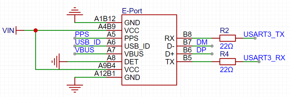
1. E-Port Interface Design
From a hardware perspective, the E-Port interface is compatible with the ordinary USB Type-C hardware interface, but the related pin functions need to be redefined. Depending on usage requirements, USB Type-C female connectors come in many types, with mounting methods including through-hole, surface mount, vertical mount, and recessed mounting, and pin counts of 2 pins, 6 pins, 16 pins, and a full-featured 24 pins.
For the E-Port interface, a 16-pin Type-C interface is sufficient.
Draw the E-Port device and bind a 16-pin Type-C package; connect the VCC pin to the VIN network, and ground GND and the DET pin used to detect load connection status; connect the serial communication to the microcontroller accordingly; and reserve relevant interfaces.
2. Power Supply Circuit
After inputting into the VIN network through the E-Port interface, first connect the power switch, and add two 4.7uF and one 0.1uF decoupling capacitors; referring to the design of the E-Port adapter board, add two TVS transient voltage suppressor diodes to absorb surge voltage and protect the downstream circuitry.

3. The STM32 circuit design
includes basic reset circuits, clock circuits, download circuits, serial port circuits, and boot mode configuration circuits. These circuits are relatively simple and can be referenced in the schematic diagram.
4. The AHT20 temperature and humidity sensor design
references the AHT20 datasheet. The circuit design is as follows:

Software
instructions: The software can use nested code blocks. It is not necessary to explain all parts of the software; only the important parts need to be explained.
The software uses DJI PSDK sample software, which can be referenced at:
https://developer.dji.com/doc/payload-sdk-tutorial/cn/
https://github.com/dji-sdk/Payload-SDK/tree/master
Connect the drone, burn the Bootloader and PSDK sample application into the chip, and the output information is as follows:

The drone connection is normal, and the drone can be controlled through the PSDK; for example, drone flight control (running in the DJI Assistant 2 software):

See the attached video for specific running effects.
The physical
circuit board is shown below:
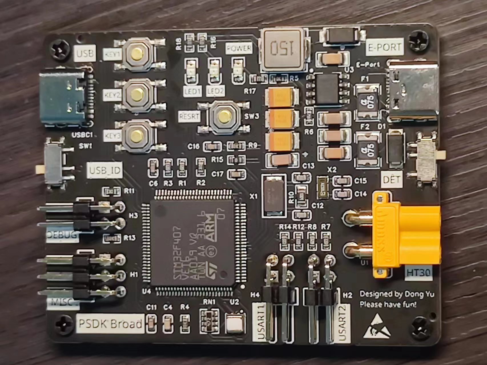
(1) The interfaces for connecting the drone and the debugging equipment are designed on the left and right sides respectively, which is convenient for connection and debugging;
(2) There are 4 screw holes around the board for connecting the PSDK bracket and fixing it on the drone.
Of course, a shell also needs to be set for it, which is also sampled at Jialichuang.
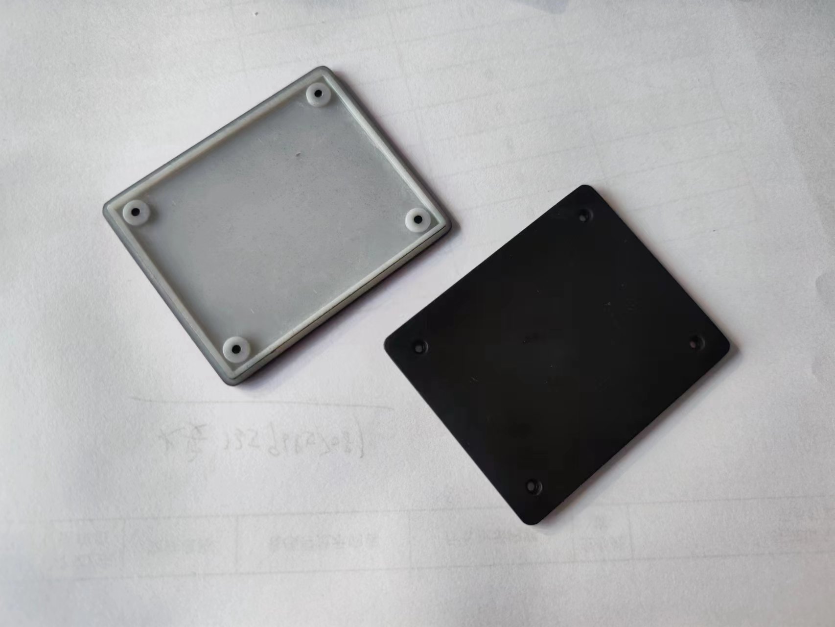
The front part here uses Imagine Black material, while the bottom uses ordinary nylon paint, which has a better effect. However, it is a bit thin because of the bottom cut, but fortunately there is a panel to support it:

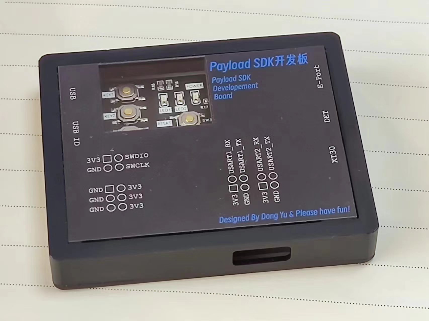
I made two kinds of acrylic panels here, black and white. The function of each interface and the definition of the header pin are marked on it.
The complete assembly is as follows:
Design Notes
When designing, you must make sure that the DET pin of E-Port is grounded, otherwise the drone will not be able to recognize the development board.
Sample Program 4.mp4
PDF_DJI Drone PSDK Development Board.zip
Altium DJI Drone PSDK Development Board.zip
PADS_DJI Drone PSDK Development Board.zip
BOM_DJI Drone PSDK Development Board.xlsx
91243
electronic


 京公网安备 11010802033920号

 MSI1812--101KB


