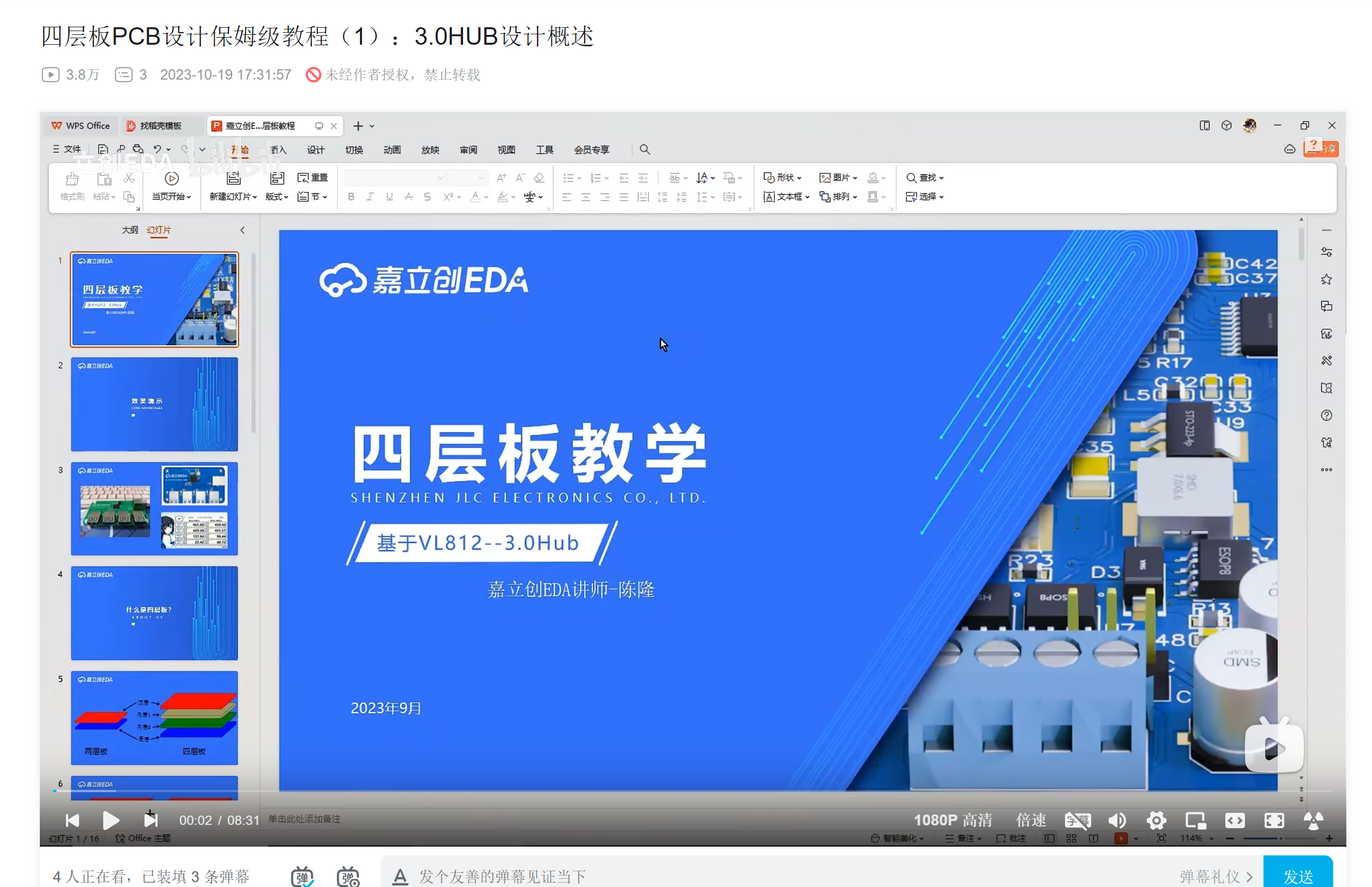
 which looked quite appealing. I thought I'd get one too, so I started browsing Taobao to buy components. Then I found a super cheap VL813 board:
 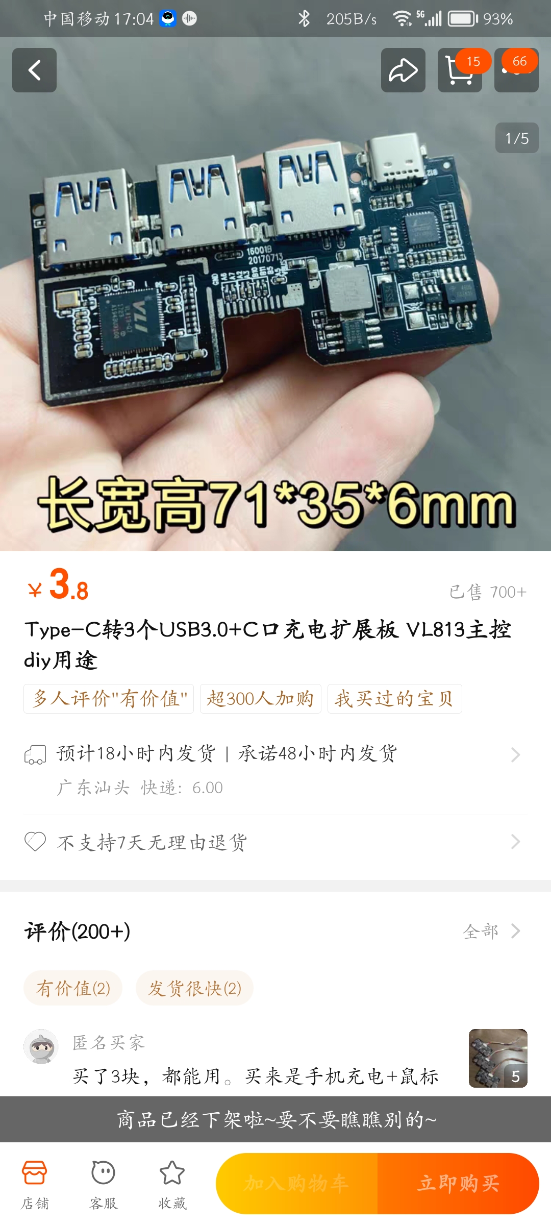 I immediately ordered 5 RMB worth, since even just disassembling the chip would be profitable!
 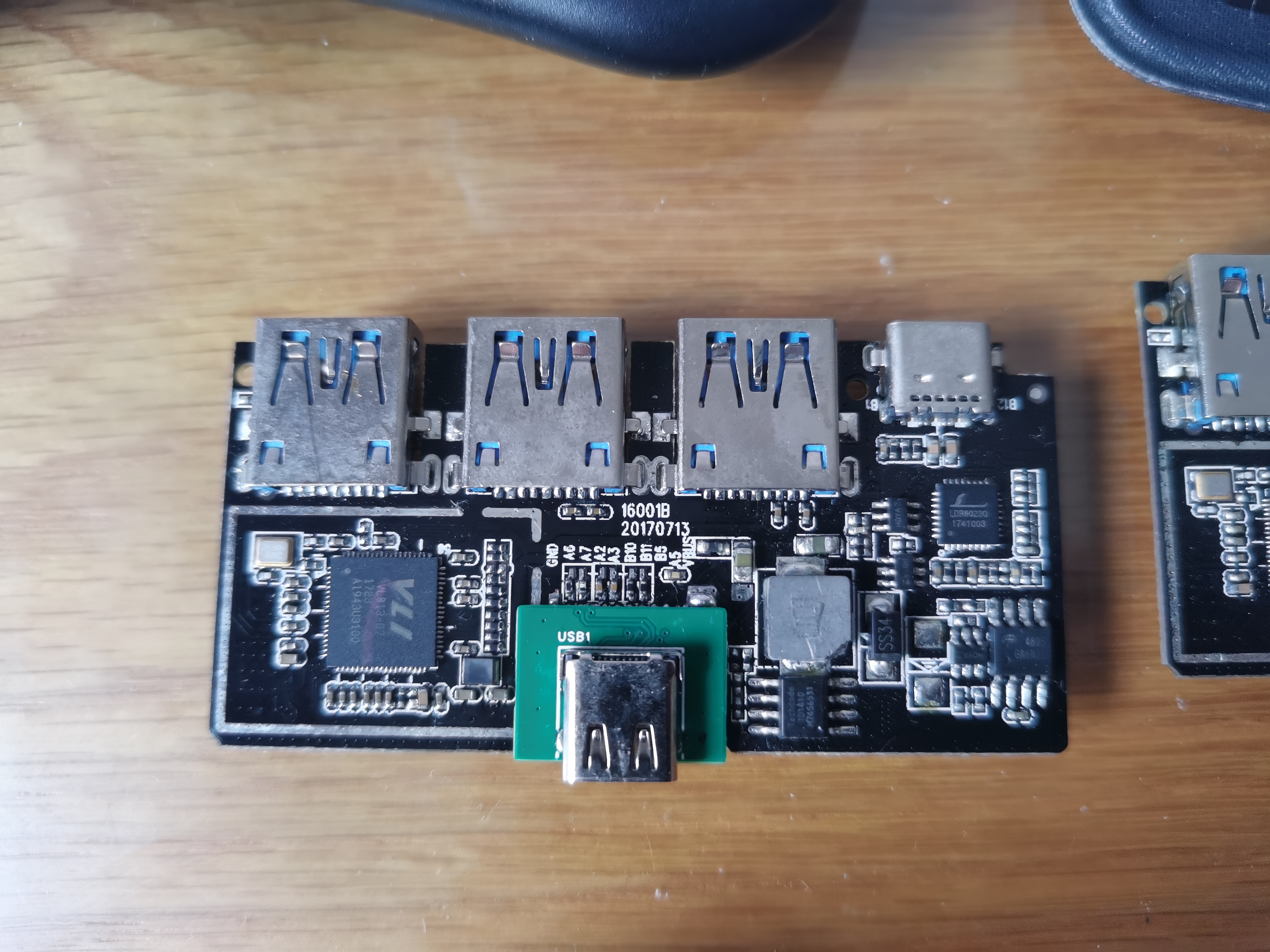 I suspected an impedance mismatch issue, so I modified it to a four-layer board and redesigned it, but it still didn't work...
  In the end, I bought a USB 3.0 cable and a Type-C male connector, soldered them according to the original design, and used it
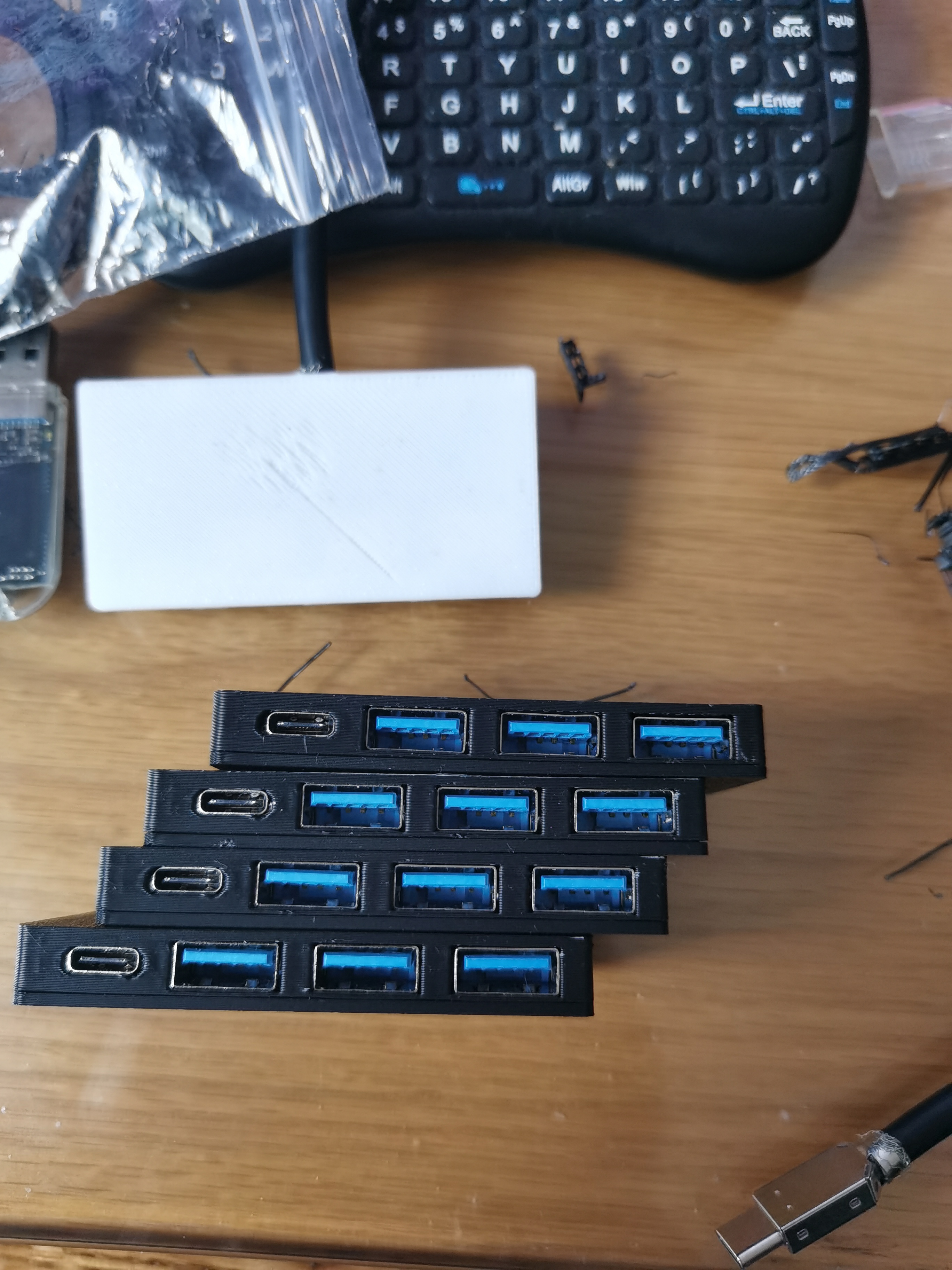
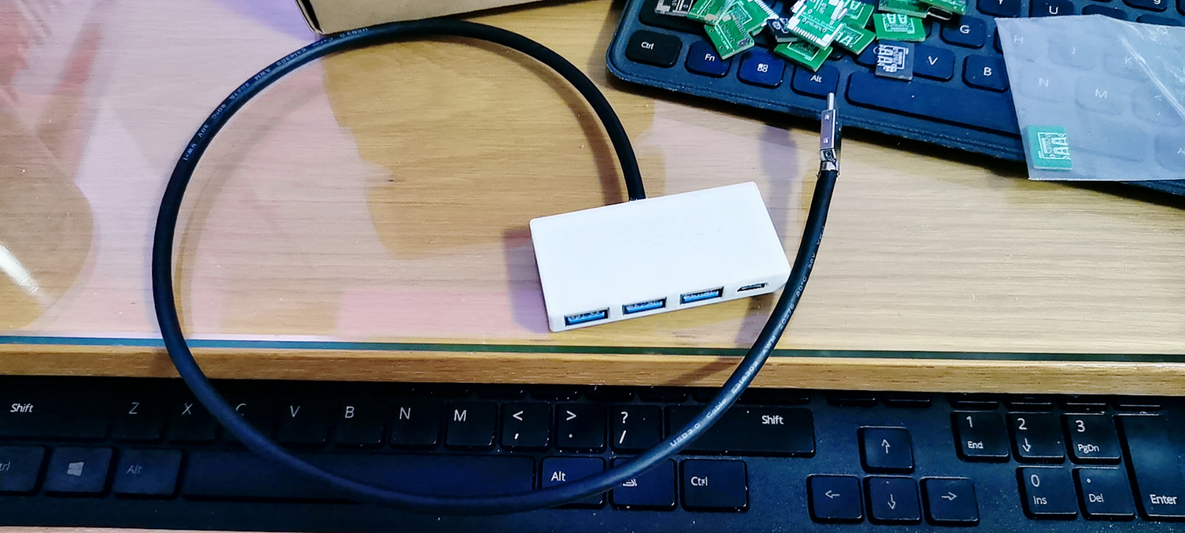
 since changing the female connector to a male connector requires swapping, does the reverse also apply?
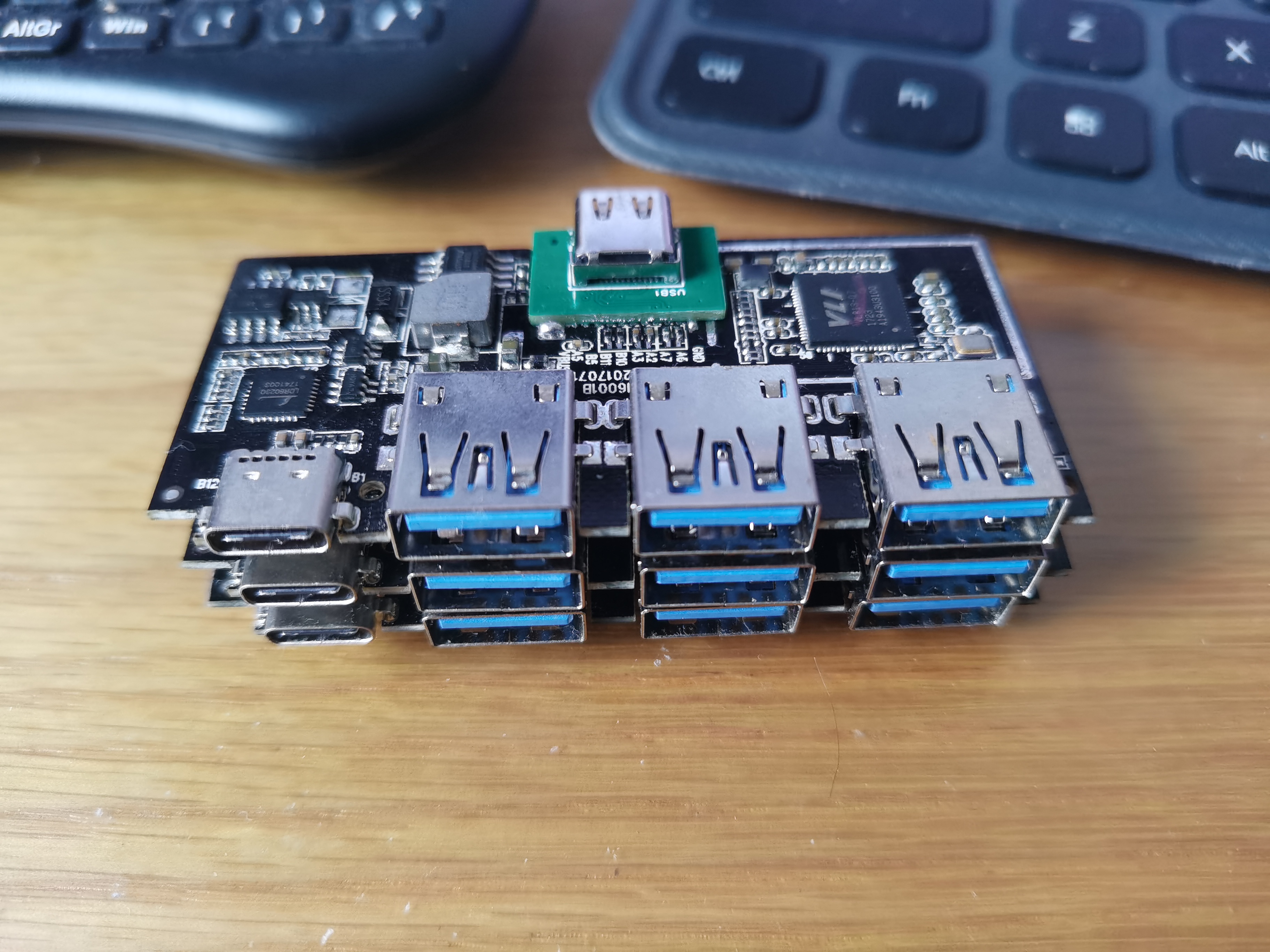
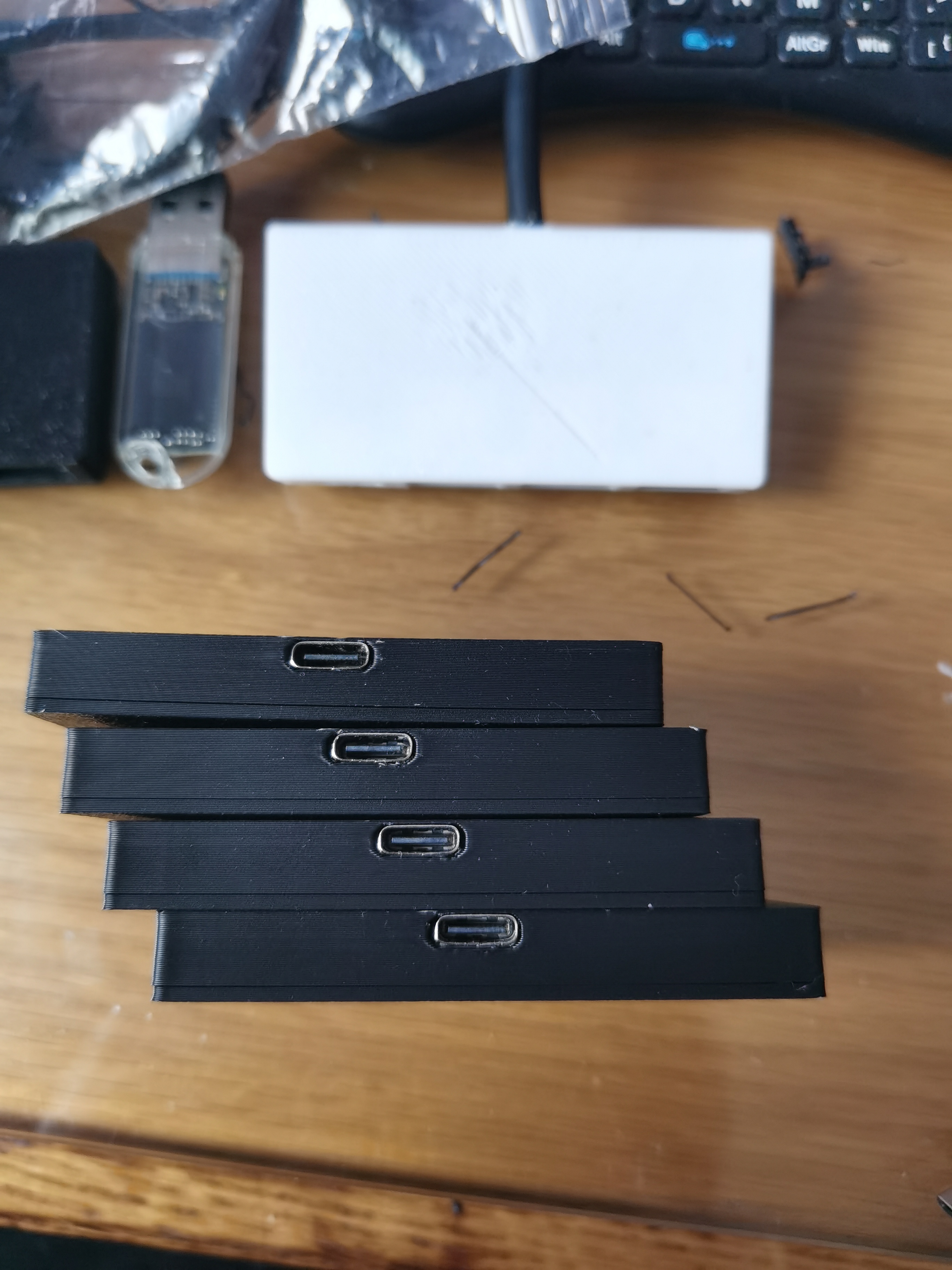
 However, it wasn't completely finished; one board still wouldn't power on...
 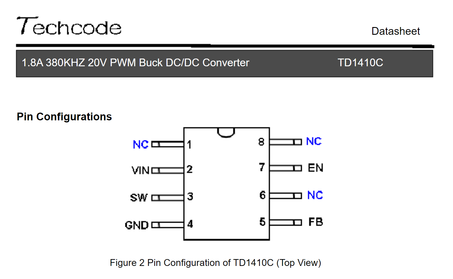 The VIN pin was receiving 5V, but there was no output. Based on my experience with Cat Wireless, I should measure the chip's enable signal. Sure enough, the EN pin only had 0.2V. To be safe, I compared it with a working board. The working board's EN pin normally has around 2.3V, so it was basically confirmed to be an enable signal problem.
  That solved the problem with the USB port; it was also a broken trace on a power pin, so I added a thicker jumper wire.
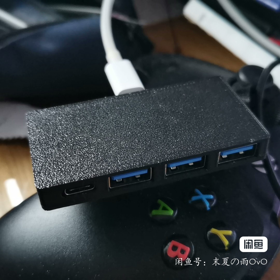

All reference designs on this site are sourced from major semiconductor manufacturers or collected online for learning and research. The copyright belongs to the semiconductor manufacturer or the original author. If you believe that the reference design of this site infringes upon your relevant rights and interests, please send us a rights notice. As a neutral platform service provider, we will take measures to delete the relevant content in accordance with relevant laws after receiving the relevant notice from the rights holder. Please send relevant notifications to email: bbs_service@eeworld.com.cn.
It is your responsibility to test the circuit yourself and determine its suitability for you. EEWorld will not be liable for direct, indirect, special, incidental, consequential or punitive damages arising from any cause or anything connected to any reference design used.
Supported by EEWorld Datasheet
EEWorld
subscription
account

EEWorld
service
account

Automotive
development
community

Robot
development
community

About Us Customer Service Contact Information Datasheet Sitemap LatestNews


Room 1530, 15th Floor, Building B,
No.18 Zhongguancun Street,
Haidian District,
Beijing, Postal Code: 100190
China
Telephone: 008610 8235 0740
 京公网安备 11010802033920号

 EL5172IS-T7


