1. Project Function Introduction:
This project is a DIY entry for the 9th LCSC Open Source Electronic Design Competition by Sensiry Sensors, which creates a temperature and humidity detector.
The hardware part references the open-source project Holocubic:
1. The MPU650 was changed to a dial, which controls the switching between different apps;
2. An I2C interface and redundant I/O ports were added for expanding other applications;
3. A TP5400 was added for charge and discharge management;
The software part references Holocubic_AIO
: 1. The status action acquisition function was changed to implement dial control of the app;
2. An app program for displaying temperature and humidity data was added;
2. Project attributes:
first public disclosure;
original;
not involved in other projects ;
3. Open source license:
Public Domain;
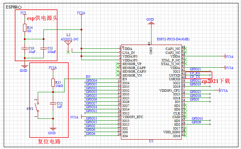
4. Hardware part : 1. ESP32 circuit diagram
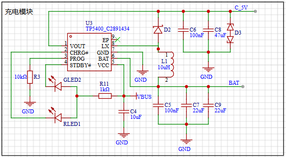
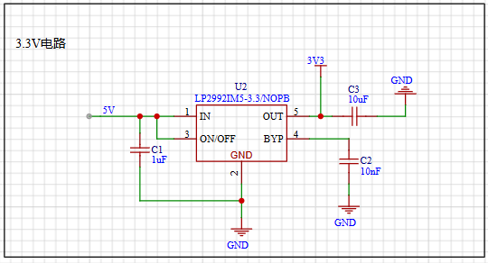
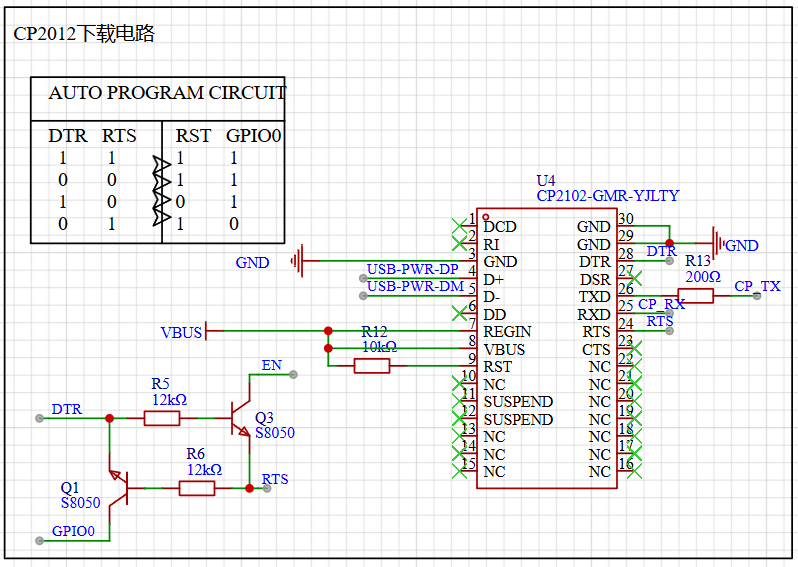
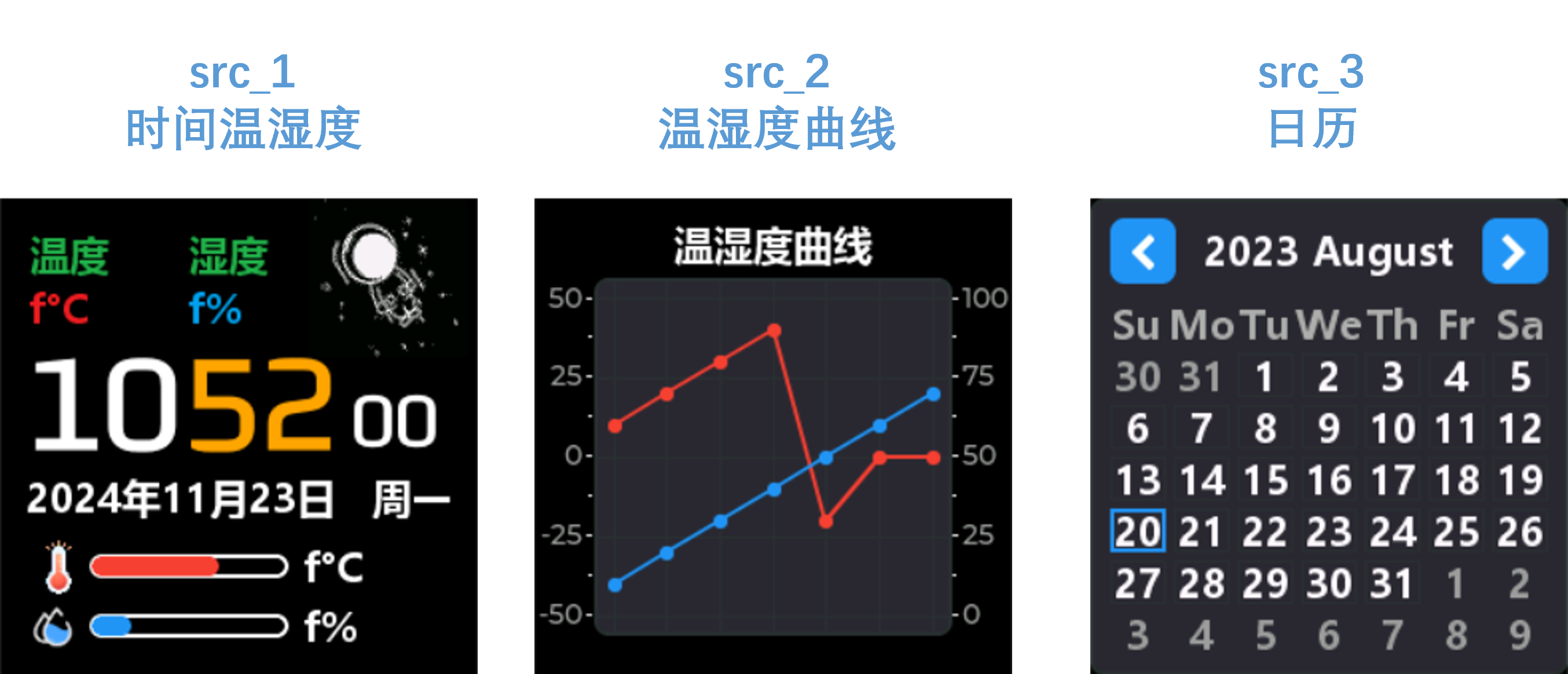
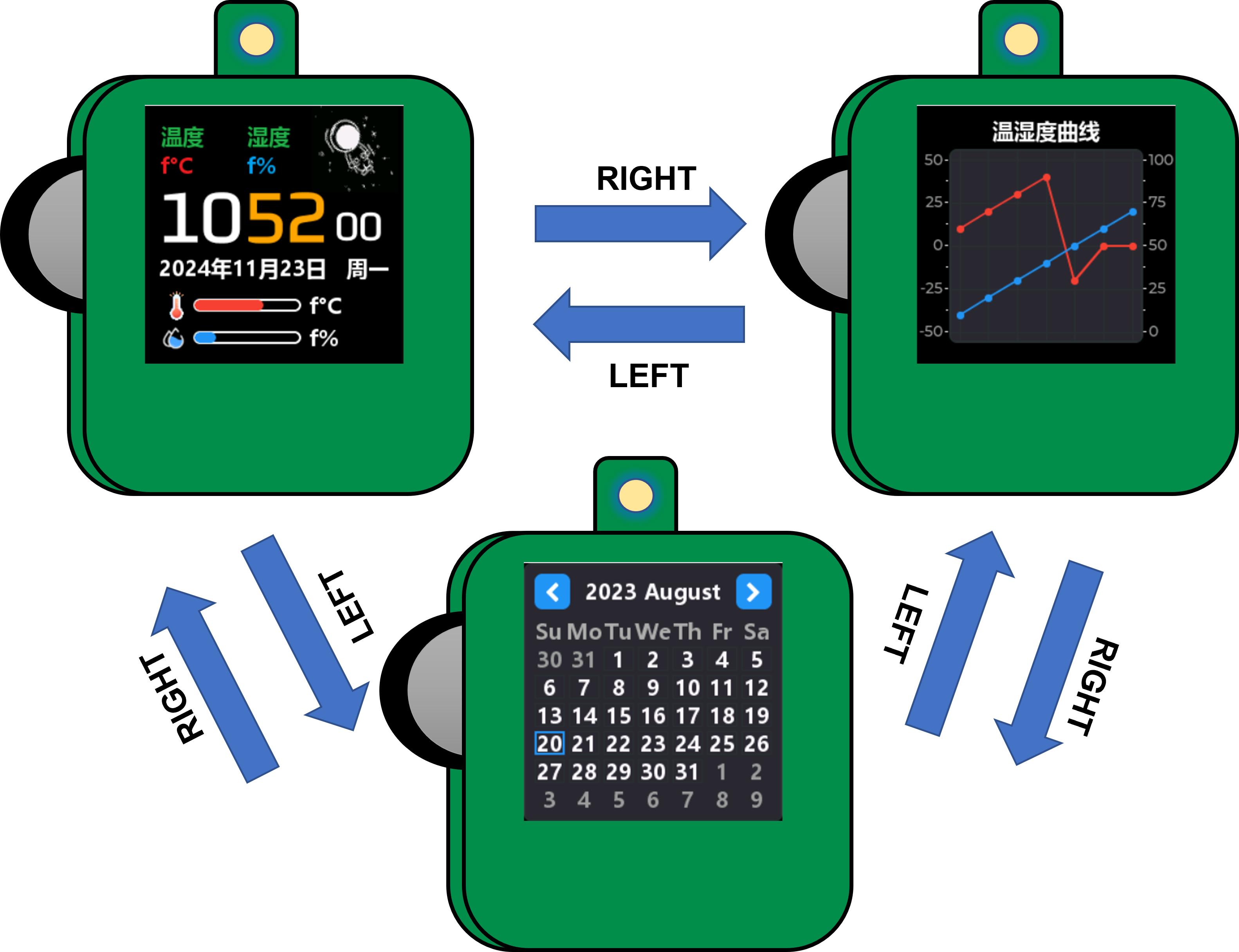
1. The minimum circuit of ESP32 mainly consists of three parts. The first is the power supply, which is provided by LP2992LP2992IM5-3.3/NOPB to ESP32 with a voltage of 3.3V. In the subsequent soldering or repair process, it can be detected through the 0Ω resistor R14; the second is the reset circuit, which mainly refers to the peripheral design schematic of the ESP32PICOD4 module. To ensure the normal power supply when the chip is powered on, EN An RC delay circuit needs to be added at the pin. The manual typically recommends R = 10 kΩ and C = 1 μF, but the specific values still need to be adjusted according to the power-on sequence of the module power supply and the power-on reset sequence of the chip. The third is the download circuit, which uses the CP2102-GMR-YJLTY to communicate with the host computer for download operations. The CP2102 automatic download circuit will be analyzed later. 2. Power Supply Section Figure 2-1 USB Power Supply Figure 2-2 Lithium Battery Charging and Discharging Figure 2-3 5V Power Supply Switching Figure 2-4 LDO Step-Down 3.3V Figure 2 Module Power Supply Circuit The power supply section of this project mainly uses USB and the lithium battery for input power. Figure 2-2 shows the lithium battery charging and discharging management circuit. The TP5400 chip has extremely low no-load power consumption (less than 10uA) and a boost output drive current capability of up to 1A. To manage the charging and discharging of the lithium battery, the charging current can be set by changing the resistance value of R3. The corresponding reference table is as follows: Table 1: Relationship between R3 and Charging Current R3 (Ω) IBAT 10k 130mA 5k 245mA 2k 560mA 1.5k 740mA 1.1k 1000mA Figure 2-3 shows a 5V power supply switching circuit. A USB and lithium battery power supply switching circuit is made using PMOS and rectifier diodes. If USB is connected, it directly powers the circuit; otherwise, the lithium battery powers the circuit. The 5V voltage can be controlled by switch SW1. Figure 2-4 shows an LDO step-down circuit, mainly for powering the ESP32 later. An LP2992 ultra-low dropout regulator is used to power the ESP. The PCB layout circuit is provided in the manual and can be referenced for PCB layout. 3. Download Circuit Diagram 3 CP2102 Automatic Download Circuit Download Mode: When the chip starts, if IO0 is low, the chip will enter download mode; Run Mode: When the chip starts, if IO0 is high, the chip will enter run mode; Set DTR = 1, RTS = 0, at this time Q1 is turned on, Q2 is turned off, EN = RTS = 0, IO0 = 1, the chip power-down resets; During the reset process, the ESP32 has an RC reset delay circuit, so EN has delayed buck and boost voltages. Set DTR = 0, RTS = 1, at this time Q1 is turned off, Q2 is turned on, EN = 1, IO0 = 0, the chip is powered on again, since IO0 is low, the chip enters download mode; Set DTR = 1, RTS = 1, at this time Q1 is turned on, Q2 is turned on, EN = 1, IO0 = 1. Ensure the chip is reset and running normally after downloading. 5. Software compilation environment: VsCode + PlatformIO. Code: climate-monitor. Figure 4 Interface display: src_1 - Displays time and temperature/humidity data, can perform network time synchronization, and displays SHT40 data acquisition. Network time synchronization is automatically calibrated every 15 minutes, and temperature/humidity data acquisition is once every 2 seconds. src_2 - Temperature and humidity data table display interface, collects temperature and humidity data every two seconds for display; src_3 - Calendar display . The state of the dial is adapted as shown in Table 2. Dial state corresponding to operation description. Dial state corresponding to operation value : RIGHT Up 0 LEFT Down 0 UP Up 1 DOWN Down 1 Change state value. Middle key 0, 1 to switch. CONFIRM Long up - BACK Long down || Long middle key - Switch the interface through the dial, network time synchronization, temperature and humidity detection, etc. Figure 5 Dial state switching description. 6. BOM list is at the end. 7. Competition LOGO verification. 8. Demo video is in the attachment. Go to view more details >


 京公网安备 11010802033920号

 OPT-1250A2I2RA


