
 III. Functional Modules
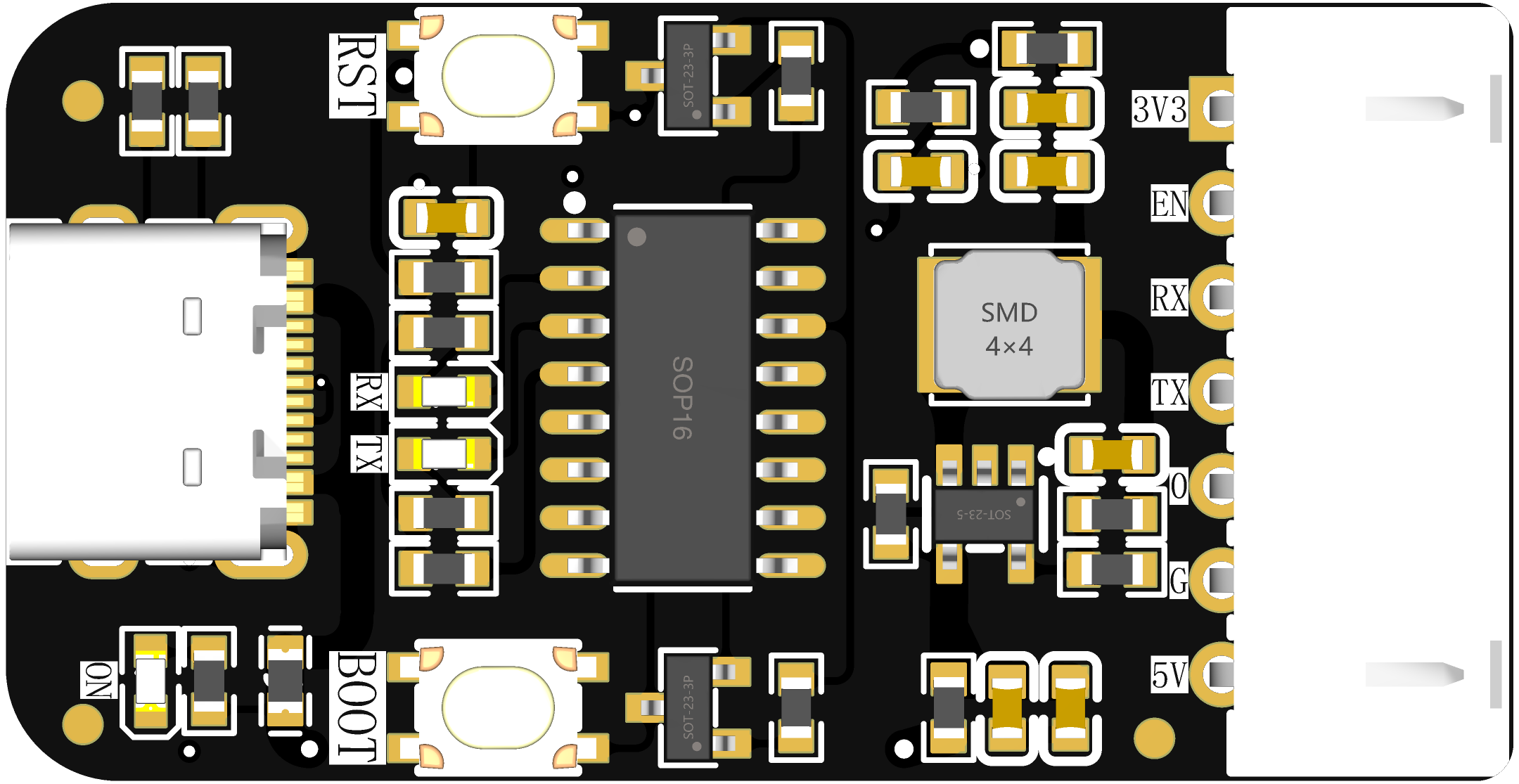
  USB interface is the more common Type-C interface, which can be plugged in either way.
 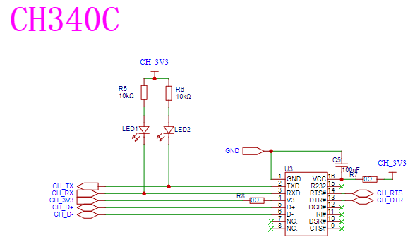 The flashing chip is the common and low-cost CH340C. RX and TX are each connected to an indicator light to indicate the flashing status. A 0 resistor is added to the power supply for easy debugging and maintenance.
 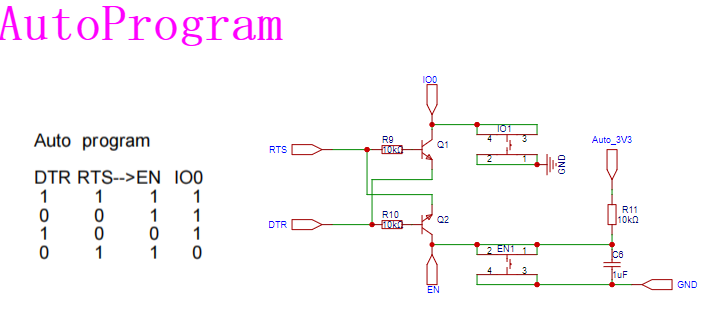 The timing of automatic flashing is shown in the figure, which can be referred to the Espressif manual for details. Two buttons are reserved for manual flashing compatibility.
  The step-down module is the common and low-cost AMS1117, which can output a current of up to 1A. The rest are standard designs and require no further explanation.
  step-down module uses the ETA3409S2F, which can output up to 3A. The choice of resistors R6 and R7 can be based on your needs; here, 100kΩ and 22kΩ are chosen. The calculation formula can be found in the chip's datasheet. Other resistors and capacitors are standard.
 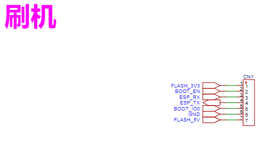 This is a 7-pin connector. Pay special attention to the pinout; carefully check this pinout on your custom-designed board!
All reference designs on this site are sourced from major semiconductor manufacturers or collected online for learning and research. The copyright belongs to the semiconductor manufacturer or the original author. If you believe that the reference design of this site infringes upon your relevant rights and interests, please send us a rights notice. As a neutral platform service provider, we will take measures to delete the relevant content in accordance with relevant laws after receiving the relevant notice from the rights holder. Please send relevant notifications to email: bbs_service@eeworld.com.cn.
It is your responsibility to test the circuit yourself and determine its suitability for you. EEWorld will not be liable for direct, indirect, special, incidental, consequential or punitive damages arising from any cause or anything connected to any reference design used.
Supported by EEWorld Datasheet
EEWorld
subscription
account

EEWorld
service
account

Automotive
development
community

Robot
development
community

About Us Customer Service Contact Information Datasheet Sitemap LatestNews


Room 1530, 15th Floor, Building B,
No.18 Zhongguancun Street,
Haidian District,
Beijing, Postal Code: 100190
China
Telephone: 008610 8235 0740
 京公网安备 11010802033920号

 FO1003P-S7-5W11206L


