1. Project Description:
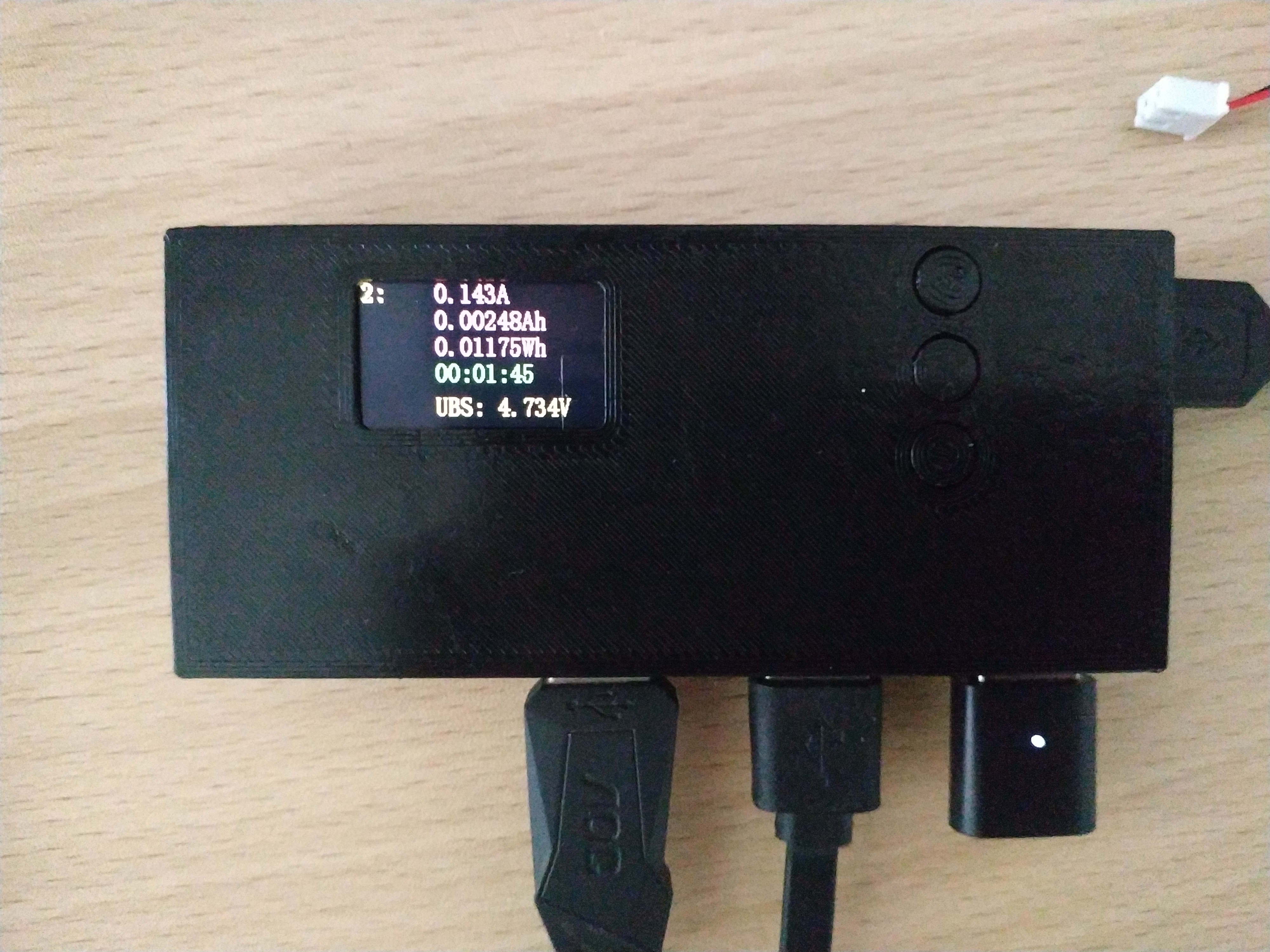
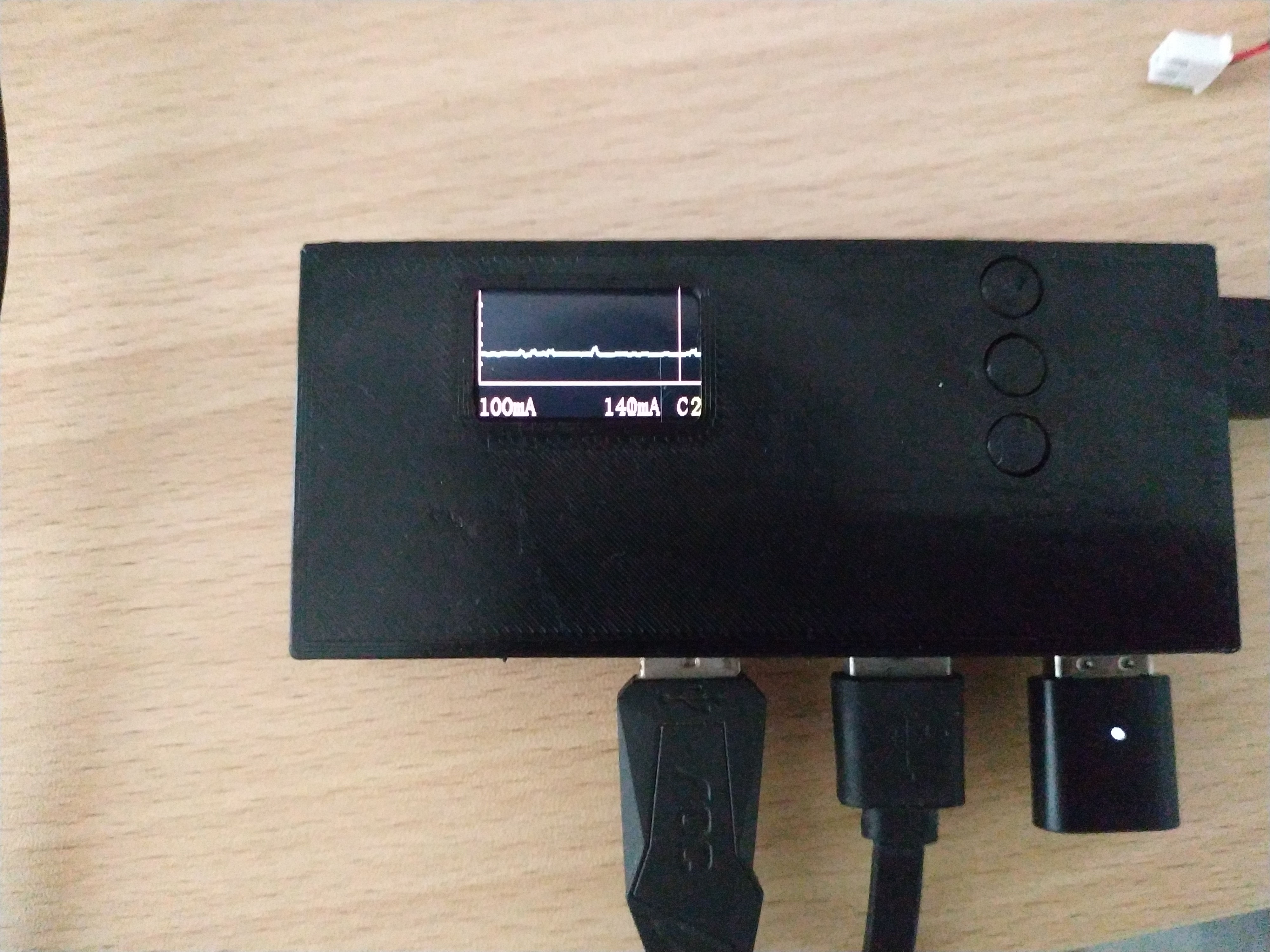
This USB hub, built using a LCSC (LCSC) development board, displays voltage and current, calculates power, and shows current waveforms.
Maximum voltage is 6.6V, and maximum current is 3.3A.
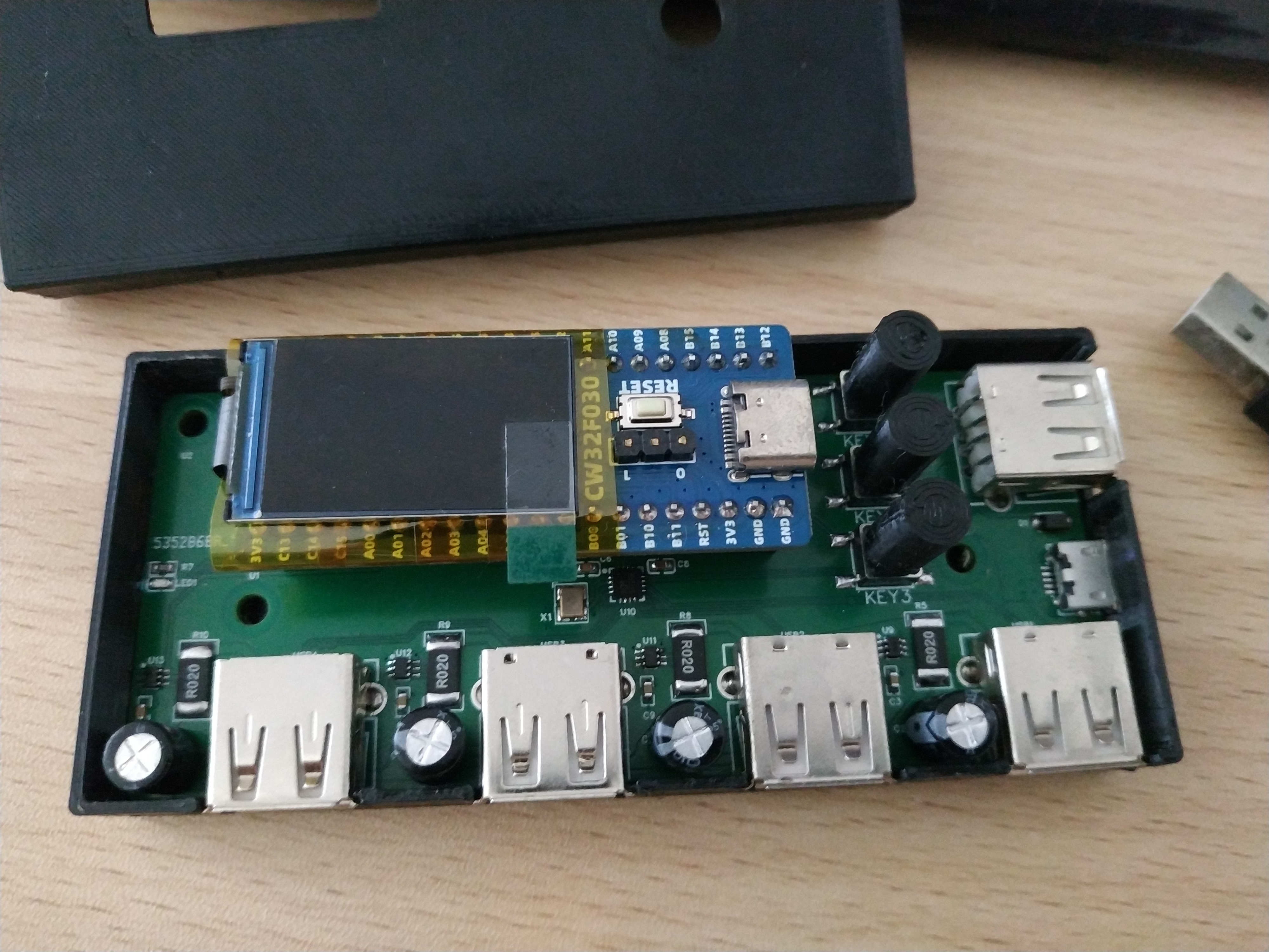
2. Circuit:
1. USB Input:
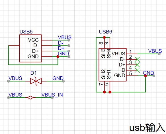
USB5 is for data input, USB6 is for external power.
2.

Uses a 1.14-inch screen and SPI protocol.
3. Current Measurement:

Uses a TP181A1-CR current sensing amplifier with a 20mΩ shunt resistor. With a chip reference voltage of 3.3V, it can measure a maximum current of 3.3A.
4. USB Hub:
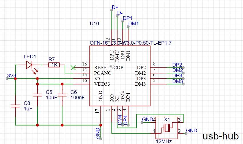
Uses a CH334P, USB 2.0, and one LED indicator.
5. Software
ADC and DMA configuration.
void adc_dma_config(void)
{
DMA_InitTypeDef DMA_InitStruct = {0};
__RCC_DMA_CLK_ENABLE();
DMA_InitStruct.DMA_DstAddress = (uint32_t)ADC4_ResultBuff; // Target address
DMA_InitStruct.DMA_DstInc = DMA_DstAddress_Increase; // Increment the target address
DMA_InitStruct.DMA_Mode = DMA_MODE_BLOCK; // BLOCK transfer mode
DMA_InitStruct.DMA_SrcAddress = (uint32_t)&CW_ADC->RESULT0; // Source address: ADC result register
DMA_InitStruct.DMA_SrcInc = DMA_SrcAddress_Fix; // Fixed source address
DMA_InitStruct.DMA_TransferCnt = 0x6; // DMA Number of transfers
DMA_InitStruct.DMA_TransferWidth = DMA_TRANSFER_WIDTH_16BIT; // Data width 16bit
DMA_InitStruct.HardTrigSource = DMA_HardTrig_ADC_TRANSCOMPLETE; //DMA_HardTrig_ADC_TRANSCOMPLETE; // Hard trigger upon ADC conversion completion
DMA_InitStruct.TrigMode = DMA_HardTrig; // Hard trigger mode
DMA_Init(CW_DMACHANNEL1, &DMA_InitStruct);
DMA_Cmd(CW_DMACHANNEL1, ENABLE);
DMA_InitStruct.DMA_DstAddress = (uint32_t)ADC3_ResultBuff; // Target address
DMA_InitStruct.DMA_DstInc = DMA_DstAddress_Increase; // Target address increments
DMA_InitStruct.DMA_Mode = DMA_MODE_BLOCK; // BLOCK transfer mode
DMA_InitStruct.DMA_SrcAddress = (uint32_t)&CW_ADC->RESULT1; // Source address
DMA_InitStruct.DMA_SrcInc = DMA_SrcAddress_Fix; // Fixed source address
DMA_InitStruct.DMA_TransferCnt = 0x6; // DMA transfer count
DMA_InitStruct.DMA_TransferWidth = DMA_TRANSFER_WIDTH_16BIT; // Data width 16bit
DMA_InitStruct.HardTrigSource = DMA_HardTrig_ADC_TRANSCOMPLETE;//DMA_HardTrig_GTIM2_OVERINT; // Hard trigger upon ADC conversion completion
DMA_InitStruct.TrigMode = DMA_HardTrig; // Hard trigger mode
DMA_Init(CW_DMACHANNEL2, &DMA_InitStruct);
DMA_Cmd(CW_DMACHANNEL2, ENABLE);
DMA_InitStruct.DMA_DstAddress = (uint32_t)ADC2_ResultBuff; // Target address
DMA_InitStruct.DMA_DstInc = DMA_DstAddress_Increase; // Increment the target address
DMA_InitStruct.DMA_Mode = DMA_MODE_BLOCK; // BLOCK transfer mode
DMA_InitStruct.DMA_SrcAddress = (uint32_t)&CW_ADC->RESULT2; // Source address
DMA_InitStruct.DMA_SrcInc = DMA_SrcAddress_Fix; // Fixed source address
DMA_InitStruct.DMA_TransferCnt = 0x6; // DMA transfer count
DMA_InitStruct.DMA_TransferWidth = DMA_TRANSFER_WIDTH_16BIT; // Data width 16 bits
DMA_InitStruct.HardTrigSource = DMA_HardTrig_ADC_TRANSCOMPLETE; //DMA_HardTrig_GTIM2_OVERINT; // Hard trigger upon ADC conversion completion
DMA_InitStruct.TrigMode = DMA_HardTrig; // Hard trigger mode
DMA_Init(CW_DMACHANNEL3, &DMA_InitStruct);
DMA_Cmd(CW_DMACHANNEL3, ENABLE);
DMA_InitStruct.DMA_DstAddress = (uint32_t)ADC1_ResultBuff; // Target address
DMA_InitStruct.DMA_DstInc = DMA_DstAddress_Increase; // Increment the destination address
DMA_InitStruct.DMA_Mode = DMA_MODE_BLOCK; // BLOCK transfer mode
DMA_InitStruct.DMA_SrcAddress = (uint32_t)&CW_ADC->RESULT3; // Source address
DMA_InitStruct.DMA_SrcInc = DMA_SrcAddress_Fix; // Fixed source address
DMA_InitStruct.DMA_TransferCnt = 0x6; // Number of DMA transfers
DMA_InitStruct.DMA_TransferWidth = DMA_TRANSFER_WIDTH_16BIT; // 16-bit data width
DMA_InitStruct.HardTrigSource = DMA_HardTrig_ADC_TRANSCOMPLETE; //DMA_HardTrig_GTIM2_OVERINT; // ADC Conversion complete, hard trigger
DMA_InitStruct.TrigMode = DMA_HardTrig; // Hard trigger mode
DMA_Init(CW_DMACHANNEL4, &DMA_InitStruct);
DMA_Cmd(CW_DMACHANNEL4, ENABLE);
}
void adc_config(void)
{
ADC_DeInit();
ADC_InitTypeDef ADC_InitStructure = {0};
ADC_SerialChTypeDef ADC_SerialChStructure = {0};
__RCC_ADC_CLK_ENABLE();
ADC_InitStructure.ADC_AccEn = ADC_AccDisable;// ADC accumulation function is disabled
ADC_InitStructure.ADC_Align = ADC_AlignRight;// Right-align the sampling results, i.e., the results are stored in bits 11~bit0
ADC_InitStructure.ADC_ClkDiv = ADC_Clk_Div4; // The ADC sampling clock is 4 times PCLK, i.e., ADCCLK = 16MHz.
ADC_InitStructure.ADC_DMAEn = ADC_DmaEnable; // DMA is triggered upon ADC conversion completion.
ADC_InitStructure.ADC_InBufEn = ADC_BufDisable; // High-speed sampling, the ADC's internal voltage follower is disabled.
ADC_InitStructure.ADC_OpMode = ADC_SingleChOneMode; // Single-pass, single-channel sampling mode.
ADC_InitStructure.ADC_SampleTime = ADC_SampTime10Clk; // Set to 10 sampling cycles, must be adjusted according to actual conditions.
ADC_InitStructure.ADC_TsEn = ADC_TsDisable; // Internal temperature sensor is disabled.
ADC_InitStructure.ADC_VrefSel = ADC_Vref_VDDA; // The sampling reference voltage is selected as VDDA.
ADC_SerialChStructure.ADC_Sqr0Chmux = ADC_SqrCh0;
ADC_SerialChStructure.ADC_Sqr1Chmux = ADC_SqrCh1;
ADC_SerialChStructure.ADC_Sqr2Chmux = ADC_SqrCh2;
ADC_SerialChStructure.ADC_Sqr3Chmux = ADC_SqrCh3;
ADC_SerialChStructure.ADC_SqrEns = ADC_SqrEns03;
ADC_SerialChStructure.ADC_InitStruct = ADC_InitStructure;
/* Continuous sampling mode for the sequence channels */
ADC_SerialChContinuousModeCfg(&ADC_SerialChStructure);
`adc_dma_config();
ADC_Enable(); // Enable ADC
ADC_SoftwareStartConvCmd(ENABLE);
}`
4: The casing
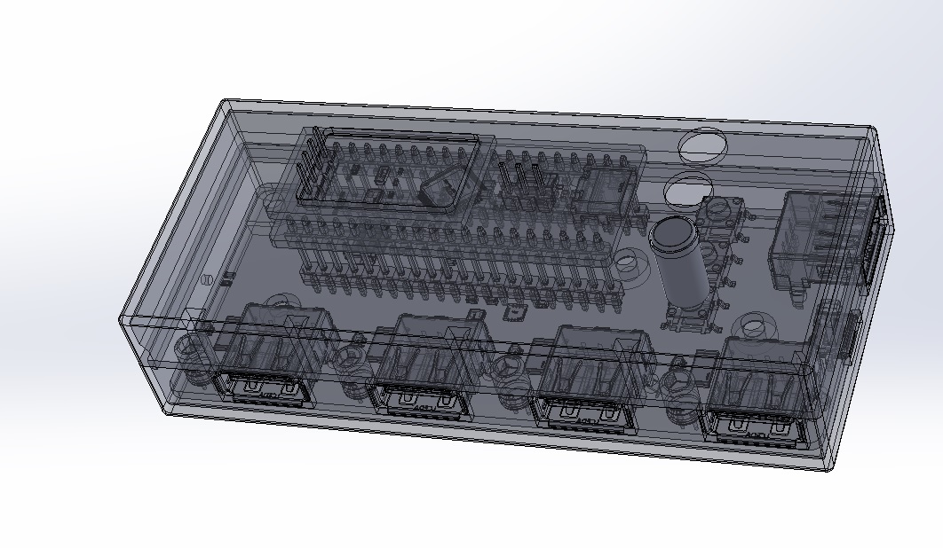
uses a SolidWorks design.
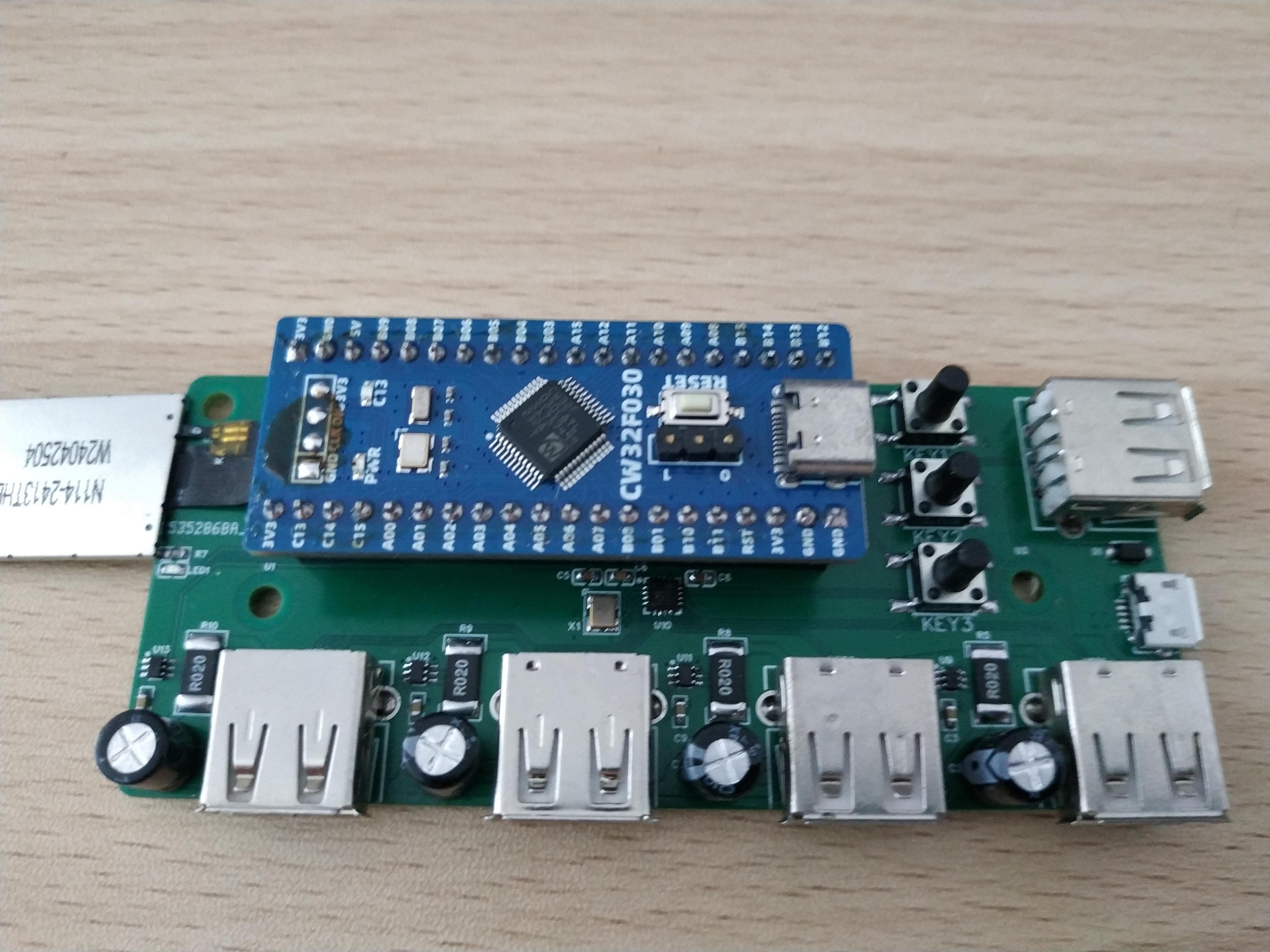
5: The actual product.

6: Video
link on Bilibili: https://www.bilibili.com/video/BV14NWWecEzg/?vd_source=a83c174a9f85373eb37ec3663e1ac747


 京公网安备 11010802033920号

 TSC80C31XXX-L20CE


