How to get negative voltage from positive voltage power supply, positive voltage to negative voltage method diagram
Source: InternetPublisher:桂花蒸 Keywords: Negative voltage positive voltage NE555 voltage power supply Updated: 2025/03/04
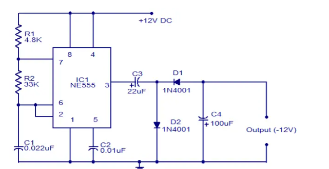
This circuit diagram shows how to get a negative voltage from a positive voltage supply. Another advantage of this circuit is that the negative voltage can be used along with the original positive supply to simulate a dual supply. This circuit is based on the timer IC NE555. The NE555 is wired as an astable multivibrator and operates at about 1KHz. Square wave output (if located at pin 3 of the IC). During the positive half of the square wave, capacitor C3 is charged through diode D2. When the output of the IC is zero, C3 is discharged through diode D2 and capacitor C4 is charged. Therefore, the voltage at the junction of D1 anode and C4 cathode will always be negative with respect to ground.
Assemble the circuit on the Vero board.
IC1 must be mounted on the bracket.
C3 and C4 must be rated for at least 25V.
Do not connect a load that consumes more than 50mA.
The negative voltage output will always be a few volts below the positive supply.
Diagram of the method of converting positive voltage to negative voltage
Method 1:
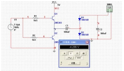
As shown in the figure above, the voltage doubler rectifier method is used. After the 5V, 1KHz sinusoidal signal is amplified by the transistor push-pull, the required negative voltage is obtained by voltage doubler rectifier! (+5V becomes -4V)
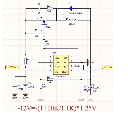
Method 2: 34063-DC-DC conversion method (using the voltage reversal principle of the switching power supply principle) Please refer to the MC34063 boost circuit for the circuit diagram, and then reverse the required voltage
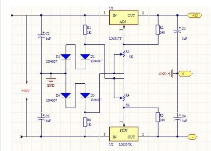
Method 3: LM317+LM337 single-turn dual-voltage method
- Current source voltage calculation method formula, how to calculate the power of the current source
- What is a battery management system? Analysis of the uses of power management systems
- Sharing layout and tips for multi-rail power supply design
- Analysis of the working principle of switching regulator
- BA6104 five-digit LED level meter driver integrated circuit basic application circuit
- The constant current source composed of two transistors can drive high power
- LED Driver ZD1680
- Parallel DC regulated power supply circuit diagram
- Voltage-current converter constructed with XTR110
- Boost drive circuit composed of RT8450
- Acousto-optic digital level detector circuit diagram
- Light-controlled street light circuit using NE555 (1)
- Use NE555 to make a three-way lantern controller
- Use NE555 to make automatic telephone lighting
- Water tower automatic water supply control circuit
- Triangular wave and square wave generator circuit diagram installed with NE555
- Overvoltage and overcurrent protection circuit diagram using NE555
- Constant current timing charger circuit diagram using NE555
- Pulse width modulation switching regulated power supply circuit diagram composed of NE555
- Pulse width modulation switching regulated power supply circuit diagram composed of NE555


 京公网安备 11010802033920号