Summing amplifier circuit diagram analysis
Source: InternetPublisher:消失的歌 Keywords: Amplifier Operational Amplifier Circuit Updated: 2025/02/20
In an inverting op amp, the inverting amplifier has an input voltage (Vin) applied to the inverting input. If you add more input resistors to the input, each with a value equal to the original input resistance (Rin), you end up with another op amp circuit called a summing amplifier circuit.
Summing Amplifier Circuit
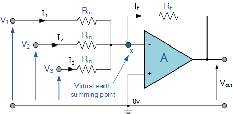
In this simple summing amplifier circuit, the output voltage (Vout) is now proportional to the sum of the input voltages V1, V2, V3, etc. We can then modify the original formula for the inverting amplifier:
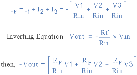
However, if all input impedances (R IN ) are equal in value, we can simplify the above formula to obtain the following output voltage:

Summing Amplifier Output Voltage Formula
Now, we have an op amp circuit that will amplify each individual input voltage and produce the same voltage as the three individual input voltages V1, V2, and V
The algebraic "SUM" of the 3 is proportional to the output voltage signal. We can also add more inputs if needed, since each individual input "sees" their own individual resistance, Rin is the only input impedance.
This is because the input signals are effectively isolated from each other by the "virtual ground" node at the inverting input of the op amp. Direct voltage addition can also be obtained when all resistors are equal and Rf equals Rin.
Note that when the summing junction is connected to the inverting input of the op amp, this circuit will produce a negative sum of any number of input voltages. Likewise, when the summing junction is connected to the non-inverting input of the op amp, it will produce a positive sum of the input voltages.
A scaling summing amplifier can be made if the individual input resistors are “NOT” equal. Then the formula must be modified to:

To simplify the math, we can rearrange the above formula so that the feedback resistor, Rf, becomes the formula that gives the output voltage:

If more input resistors are connected to the inverting input terminal of the amplifier, the output voltage can be easily calculated. The input impedance of each individual channel is the value of their respective input resistors, i.e. R1, R2, R3
…wait.
Sometimes we need a summing circuit to add two or more voltage signals together without any amplification. By making all the resistors in the circuit the same value, R, the op amp will have a voltage gain of unity, and the output voltage will be equal to the direct sum of all the input voltages, as shown below:
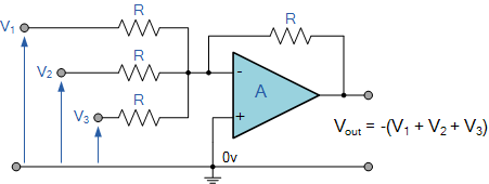
Summing Amplifier Example 1:
Find the output voltage of the following summing amplifier circuit.
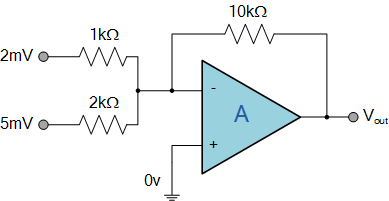
Summing Amplifier
Using the formula found previously, we obtain the circuit gain:

Now, we can substitute the values of the resistors in the circuit as follows:
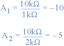
We know that the output voltage is the sum of the two amplified input signals, and its calculation formula is:

The output voltage of the above summing amplifier circuit is then -45 mV and the output voltage of its inverting amplifier is negative.
Non-inverting Summing Amplifier
However, instead of constructing an inverting summing amplifier, we can also use the non-inverting input of an op amp to produce a non-inverting summing amplifier. We have seen above that an inverting summing amplifier produces a negative sum of its input voltages, and it follows that a non-inverting summing amplifier configuration will produce a positive sum of its input voltages.
As the name implies, the non-inverting summing amplifier is based on the configuration of a non-inverting operational amplifier circuit, where the input (AC or DC) is applied to the non-inverting (+) terminal and the desired negative is applied to the output signal (V
OUT) is fed back to the inverting (-) terminal to achieve feedback and gain.
Non-inverting Summing Amplifier

So, what are the advantages of a non-inverting configuration over an inverting summing amplifier configuration? Aside from the most obvious fact, the output voltage, V
OUT is in phase with the input, and the output voltage is the weighted sum of all its inputs, which are themselves determined by their resistance ratios, which is the biggest advantage of a non-inverting summing amplifier. Because there is no virtual ground between the input terminals, its input impedance is much higher than that of a standard inverting amplifier configuration.
Likewise, if the closed-loop voltage gain of the op amp is changed, the input summing portion of the circuit is unaffected. However, there is more math involved in selecting the weighted gains for each individual input at the summing point, especially when there are more than two inputs that each have a different weighting factor. However, if all the inputs have the same resistor value, there is much less math involved.
If the closed-loop gain of a noninverting op amp is made equal to the number of summing inputs, the op amp output voltage will be exactly equal to the sum of all the input voltages. That is, for a two-input noninverting summing amplifier, the op amp gain is equal to 2, for a three-input noninverting amplifier, the op amp gain is 3, and so on. This is because the current flowing into each input resistor is a function of all of its input voltages. If the input resistors are all equal (R
1 = R 2), then the circulating currents cancel because they cannot flow into the high impedance noninverting input of the op amp, and the voutput voltage becomes the sum of its inputs.
Therefore, for a 2-input non-inverting summing amplifier, the current flowing into the input terminals can be defined as:
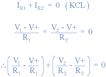
If we make both the input resistances equal in value, then - [R1 = R2 = R].

The standard formula for the voltage gain of a non-inverting summing amplifier circuit is:
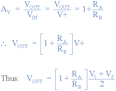
The closed-loop voltage gain of a non-inverting amplifier, V, is given by: 1 + RA / RB. If we make this closed-loop voltage gain equal to 2 by making RA = RB, then the output voltage V
O is equal to the sum of all input voltages.
Non-inverting summing amplifier output voltage
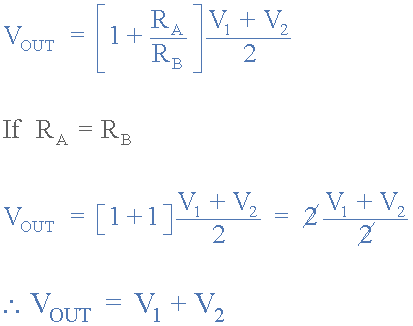
Therefore, for a 3-input non-inverting summing amplifier configuration, setting the closed-loop voltage gain to 3 will make V equal to the three input voltages V1, V2, and V
3. Similarly, for a four-input summer, the closed-loop voltage gain will be 4, for a five-input summer it will be 5, and so on. Also note that if the amplifier of the summing circuit is connected as a unity follower, and R
If A is equal to zero and RB is equal to infinity, then in the absence of voltage gain, the output voltage V OUT will be exactly equal to the average voltage of all inputs, that is, V OUT = (V 1 + V 2) / 2.
Summing Amplifier Applications
So can we use the summing amplifier for inverting or non-inverting. If the input resistors of the summing amplifier are connected to a potentiometer, the individual input signals can be mixed together in varying amounts.
For example, when measuring temperature, you can add a negative offset voltage to make the output voltage or display read “
0", or make an audio mixer to take channels from different sources (vocals, instruments, etc.) and then combine them to send to an audio amplifier.
Summing Amplifier Audio Mixer
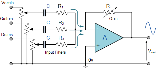
Another useful application of a summing amplifier is as a weighted digital-to-analog converter (DAC). If the input resistance of the summing amplifier, R
IN is a value of double for each input, such as 1kΩ, 2kΩ, 4kΩ, 8kΩ, 16kΩ, etc., then the digital logic voltage, a logic level "0" or a logic level "1" on these inputs will produce an output that is the weighted sum of the digital inputs. Consider the circuit below.
Digital to Analog Converter
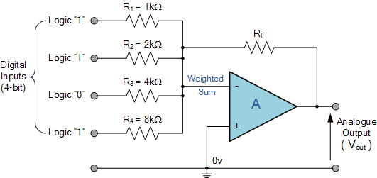
Of course, this is a simple example. In this DAC summing amplifier circuit, the number of bits that make up the input data word ultimately determines what percentage of the full-scale analog output voltage the output step voltage represents.
Likewise, the accuracy of this full-scale analog output depends on the voltage level of the input bit, which is always 0V for a “0” and 5V for a “1”, and the accuracy of the resistance value used for the input resistor, R IN .
- What is a touch sensor? How does a touch sensor work?
- Understanding the capacitance formula, what are the types of capacitors
- The unidirectional conduction current of the diode, the diode and its common uses
- How do pull-up resistors work? How do I choose a pull-up resistor value?
- How are diodes made using semiconductors?
- Ideal characteristics of operational amplifiers/pin configurations/gain types/primary applications
- Capacitance detection circuit configuration, how to deal with low frequency and high frequency noise?
- What is power factor and three ways to improve it
- Basic characteristics/working principles and application circuits of tunnel diodes
- Share an interesting LED decoration project
- Sense amplifier circuit
- Ultrasonic proximity sensor circuit
- Inductively Coupled Voltage Amplifier Circuit
- Amplifier circuit diagram based on 50Ω linear
- A crystal controlled local oscillator circuit diagram
- Intrinsically protected safety op amp
- Basic Op Amp Differential Amplifier
- Infrared remote control transmitter/receiver circuit
- OTL low frequency power amplifier circuit
- The latest application principle circuit of CFB amplifier


 京公网安备 11010802033920号