Ideal characteristics of operational amplifiers/pin configurations/gain types/primary applications
Source: InternetPublisher:念念Brown Keywords: Operational amplifier analog electronic circuit Updated: 2025/01/21
The operational amplifier (OPerational AMPlifier) is a basic component of analog electronic circuits.
They are linear devices with all the characteristics of a DC amplifier. You can use external resistors or capacitors on op amps, and there are many different ways to make them into different forms of amplifiers, such as inverting amplifiers, non-inverting amplifiers, voltage followers, comparators, differential amplifiers, summing amplifiers, integrators, etc.
Operational amplifiers can be single, dual, quad, etc. They have excellent performance with very low input current and voltage. An ideal operational amplifier has three important terminals in addition to other terminals. The input terminals are the inverting input and the non-inverting input. The third terminal is the output which can sink and source current and voltage. The output signal is the amplifier gain multiplied by the input signal.
5 Desirable Characteristics of Operational Amplifiers
1. Open-loop gain
Open-loop gain is the gain of the op amp without positive or negative feedback. An ideal op amp would have infinite open-loop gain, but it is usually between 20,000 and 2,000,000.
2. Input impedance
It is the ratio of input voltage to input current, which should be infinite without any leakage from the supplies to the inputs. But in most op amps there is some picoamp leakage.
3. Output impedance
An ideal op amp would have zero output impedance and no internal resistance, so it can deliver full current to the load connected to its output.
4. Bandwidth
An ideal op amp would have infinite frequency response so that it could amplify any frequency from DC signals up to AC frequencies, but most op amps have limited bandwidth.
5. Offset
When the voltage difference between the inputs is zero, the output of the op amp should be zero. But in most op amps, the output is not zero when turned off, but a tiny voltage is generated.
uA741 operational amplifier pin configuration
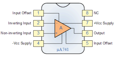
In a typical op amp there will be 8 pins, these are:
Pin1 - Offset Null
Pin2 – Inverting input INV
Pin3 – Non inverting input Non-INV
Pin4 - Ground- Negative supply
Pin5 - Offset Null
Pin6 – Output
Pin7 – Positive supply
Pin8 – Strobe
4 Types of Gain in Op Amps
Voltage Gain - Voltage in and voltage out;
Current Gain - Current in and current out;
Transconductance - voltage input and current output;
Transimpedance - Current input and voltage output.
Main Applications of Operational Amplifiers
1. Zoom in
The amplified output signal of the operational amplifier is the difference between the two input signals.
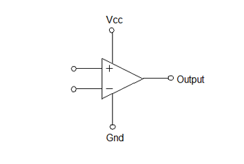
The above diagram is a simple connection of an op amp. If the same voltage is given to both inputs, the op amp will take the difference between the two voltages, which will be 0. The op amp multiplies this by the gain of 1,000,000, so the output voltage is 0. When 2 volts is given to one input and 1 volt to the other, then the op amp will take the difference and multiply it by the gain. That is 1 volt x 1,000,000. But this gain is very high, so to reduce the gain, feedback from the output to the input is usually done through a resistor.
Inverting Amplifier:
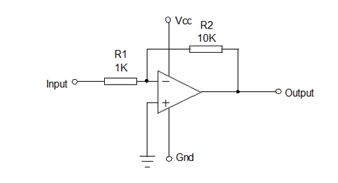
The circuit shown in the figure above is an inverting amplifier with its non-inverting input connected to ground. The two resistors R1 and R2 are connected in the circuit in such a way that R1 feeds the input signal and R2 returns the output to the inverting input. Here, when the input signal is positive, the output will be negative and vice versa. The voltage change of the output with respect to the input depends on the ratio of the resistors R1 and R2. R1 is selected as 1K and R2 is selected as 10K. If the input receives 1 volt, 1 mA current will flow through R1 and the output must become 10
volts to provide 1 mA through R2 and maintain zero voltage at the inverting input. Therefore, the voltage gain is R2/R1, which is 10K/1K=10.
Non-inverting amplifier:
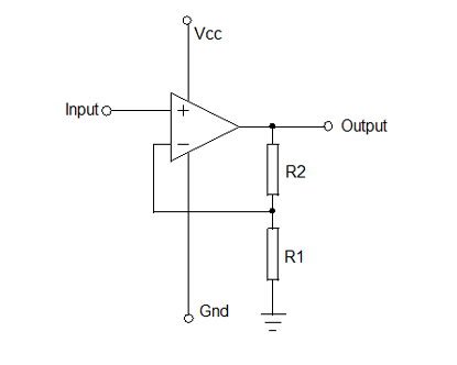
The circuit shown above is a non-inverting amplifier, here the non-inverting input receives the signal and the inverting input is connected between R2 and R1. When the input signal moves positive or negative, the output will be in phase and keep the voltage at the inverting input the same as the voltage at the non-inverting input. In this case, the voltage gain will always be above 1, so it is (1+R2/R1).
2. Voltage Follower
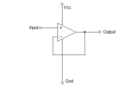
The above circuit is a voltage follower. Here it provides high input impedance, low output impedance. When the input voltage changes, the output and inverting input will change equally.
3. Comparator
The op amp compares the voltage applied to one input with the voltage applied to the other input, and any difference between the voltages (if small) will drive the op amp into saturation. When the voltages supplied to both inputs are of the same magnitude and the same polarity, the output of the op amp is 0 volts.
Comparators produce finite output voltages that can be easily interfaced with digital logic, even if verification of compatibility is required.
- Voltage divider circuit calculation formula, where to find the voltage divider circuit?
- How do pull-up resistors work? How do I choose a pull-up resistor value?
- The Importance and Ideal Model of Impedance Matching
- FPGA Features and Architecture
- Classification and characteristics of operational amplifiers, classification and characteristics of operational amplifiers
- How to calculate the value of capacitors in parallel?
- Working principle and truth table of JK flip-flop
- Causes of PCB deformation How to prevent circuit board bending and warping
- Share a Motorola amplifier circuit
- LED lights that “drain” battery power
- High Stability Thermocouple Amplifier
- AC voltage current
- Practical amplifier circuit consisting of operational amplifier LM386 e
- Low Q Gain Band Pass Filter Amplifier
- One of the thermostatic control circuits using operational amplifiersb
- One of the thermostatic control circuits using operational amplifiers a
- Parallel output connection
- A connection circuit using only 5V power supply
- Motor forward/reverse circuit composed of power operational amplifier
- Tuned notch filter using an operational amplifier


 京公网安备 11010802033920号