USB RGB LED Controller
Source: InternetPublisher:wyrB1kOu Keywords: USB LED controller Updated: 2025/11/21
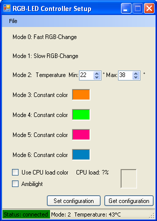
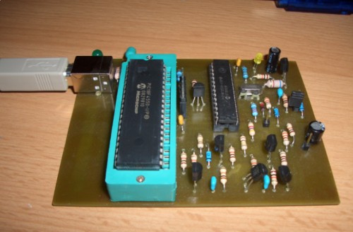
This is a feature-rich LED controller board with many convenient features. The USB interface allows for direct selection of operating modes on the PC screen, eliminating the need for additional input devices on the board. The project comes pre-programmed with several modes, including slow and fast color changes, and temperature-based colors (the color depends on the temperature measured from a temperature sensor (DS1821)). Other modes include constant colors that can be configured via a C# Windows application. In fact, there are even more possibilities, especially when using USB. Write your own application or use a PC application to represent CPU load or other content using RGB colors. The project is built around a PIC18F2550 microcontroller, which has a built-in USB interface. Therefore, the USB requires only a few components, allowing you to focus on other parts of the circuitry.
This project is a full-color LED controller that can be configured via USB connection. The color of the connected LEDs (common anode only) depends on the selected operating mode:
Slow color change (approximately 40 minutes)
Rapid color change (approximately 2 minutes)
Temperature-based color (temperature range adjustable)
Constant Color 1
Constant Color 2
Constant Color 3
Constant Color 4
In color-changing mode, the LEDs automatically cycle through all possible colors of the rainbow within a certain time period.
In temperature-based mode, the color changes according to the temperature measured by the DS1821 sensor. At home, I use this mode to light it up based on the temperature of the radiator.
In constant color mode, the LED color is constant, but it can be configured via USB using a C# Windows application.
Using this application, the circuit can also be used to light up LEDs, changing the color from blue to red, depending on the PC's CPU load or the screen content.
The following components are needed to build an RGB LED controller:
C1 220nF
C2 100nF
C3 10μF
C4 47μF
C5 22pF
C6 22pF
IC1 PIC18F2550_28DIP
IC2 7805
S1 button
PT1 PTC660
Q1 20MHz
T1 IRFZ34N
T2 IRFZ34N
T3 IRFZ34N
R1 4.7kΩ
R2 4.7kΩ
R3 4.7kΩ
R4 100kΩ
R5 100kΩ
R6 100kΩ
R7 22Ω
R8 22Ω
R9 180Ω
R10 180Ω
R11 180Ω
SV1 4-pin connector
SV2 3-pin connector
USB1 MINI-USB
X2 connector
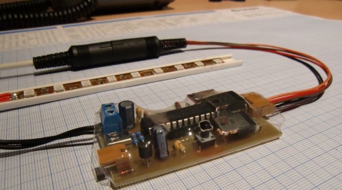
Flexible 12V LED light strip, 13.5cm, RGB
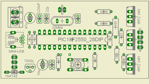
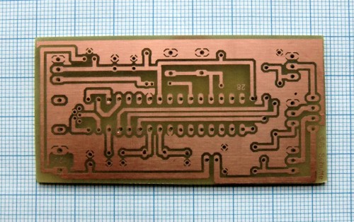
First, a PCB needs to be created. The image above shows the PCB layout. The Eagle file is included in the project download.
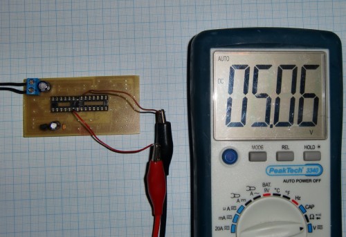
Next, solder the 5V components required to power the microcontroller onto the PCB. Once completed, supply 12V and check that the microcontroller has 5V (pin 8 = GND, pin 20 = +5V). Then, you can solder the remaining components.
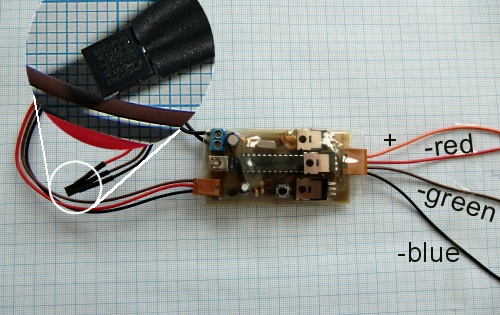
The diagram below shows how to connect the LED strip (common anode) and the wiring of the DS18S20.
Last but not least, the PIC needs to be programmed accordingly. This is done in three steps:
1. Insert the unprogrammed PIC18F2550 into your programmer of choice (I used a homemade SPRUT Brenner 8). Use this programmer to burn the USB bootloader (18f2550_boot_rb4.hex) into the PIC. The bootloader is provided with the project download. Configuration bits are included in the hex file.
2. Now insert the PIC into the circuit you just built and connect it to your PC via USB cable. Then, while holding down the mode button on the circuit, power on the circuit. This will put the PIC into boot loading mode. XP/Vista will request a driver. You provide the driver provided by the Microchip USB Framework installation (C:\Microchip Solutions\USB Device - MCHPUSB - Generic Driver DemoDriver and inf), and the device will be recognized and listed in the Device Manager.
3. Finally, the application firmware (RGBController.hex) can be programmed into the PIC using the PDFSUSB application provided by the Microchip USB Framework.
Now, you can interrupt the power to the circuit to reboot the PIC (this time without pressing the mode button), allowing the PIC to enter application mode. The connected LEDs should now light up. If Windows requests the driver again, please use the driver provided in my project download (located in the ConfigurationUIWinXP_USBDriver folder). Now press the mode button once to initialize the PIC (this only needs to be done once).
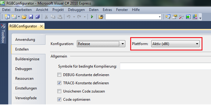
If you now launch the Windows application (ConfigurationUIRGBConfigurator inDebugRGBConfigurator.exe), you should be able to configure the PIC according to your needs, as shown in the first image above.
Please note:
To launch on Windows 7, please use this version of the software. It uses a newer version of the Microchip USB API DLL (mpusbapi.dll, version 2.6a) and is compiled with the correct options to work on 64-bit systems.


- Two-wire flashing light
- A dimming desk lamp that can automatically control brightness according to the environment
- Making a photometer with light measuring function
- USB powered portable light
- DCD-1240 multifunctional rechargeable lighting
- Six LED stereo VU display circuit built with IC LM3915
- Blinking LED circuit diagram based on LDR and resistor
- LED Flasher circuit using 2 transistors for LED switching
- Use MC1455PIG to make automatic cycle light-emitting diode circuit
- Gas flameout alarm circuit
- Provides USB Type-C® port chip solutions for lithium battery-powered devices
- STMicroelectronics USB Type-C port protection IC technology
- Additional power circuit design for USB devices
- Charger circuit powered by USB and adapter
- Based on TNY264P5 Volt/1.5A switching power supply circuit diagram
- USB lithium battery charging circuit and PCB schematic diagram
- USB device additional power
- USB signal generation circuit
- 555 timer disconnection photoelectric isolation safety protection circuit
- Breathing light circuit diagram designed by NE555


 京公网安备 11010802033920号