Active Clamp Forward Converter Single Switch Power Supply Topology
Source: InternetPublisher:aerobotics Keywords: Power supply topology forward converter Updated: 2025/06/27
Global concerns about rising energy costs, environmental protection and energy sustainability are driving the European Union, California and other places to introduce regulations to reduce the energy consumption of electronic equipment. AC input power, whether stand-alone or integrated into electronic equipment, will cause a certain amount of energy waste. First, the efficiency of the power supply cannot be 100%, and some energy is wasted when the power supply is working under heavy load. Second, when the load is not in use, the power supply connected to the AC line consumes energy in the form of standby power consumption.
In recent years, the requirements for power supply efficiency levels have become increasingly stringent. Recently, efficiencies of more than 80% have become the basic standard. New initiatives are requiring efficiency standards of 87% and above. In addition, the old method of measuring efficiency only at full load has been eliminated. The new standards now involve a four-point average of 25%, 50%, 75% and 100% of the rated load. Similarly, the maximum allowable standby power consumption has become increasingly restricted, with the European Union proposing that all devices should consume less than 500mW of standby power, and in the case of the TVs we will discuss, less than 200mW. Outside of the expert field of high-efficiency power supply design, AC input power supplies used in electronic equipment with power ranging from 1W to 500W have traditionally been based on two main topologies: the standard (or hard-switching) flyback topology, and the two-switch forward topology. Both topologies are well understood, and the problems they present, and how to avoid them, are well known in the industry. However, as the requirements for efficiency continue to increase, these two topologies will gradually be replaced by three new topologies: quasi-resonant flyback topology, LLC resonant converter topology and asymmetric half-bridge topology. The quasi-resonant flyback topology has been successfully used in the lowest power level to more than 200W. In the 70W-100W range, the LLC resonant converter is more efficient than the quasi-resonant flyback topology.
With so much attention being paid to the flyback and LLC power conversion topologies, I thought it was time to visit an old friend: the forward topology. It has been widely used for decades, and for good reason. It is difficult to find a single-ended topology that offers consistently high scores in terms of design simplicity, low cost, and high efficiency. It is particularly well suited for low to medium power applications (less than 300W) that require high output current.
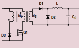
Figure 1: Basic forward topology from TI's Power Topology circuit
The main advantages of a forward converter over a flyback include better transformer utilization, lower peak current, and filtered output.
Alas, the single-switch forward converter is not without inherent problems such as transformer core saturation, voltage spikes due to transformer leakage inductance, switching losses, etc. Resistor-capacitor-diode (RCD) clamping is used to solve the transformer reset problem, while active clamp forward (ACF) uses an auxiliary switch to replace the diode and resistor of the RCD clamp to reduce leakage. Zero voltage switching (ZVS) technology is used to solve the switching losses.
We compared the results using various methods with the two main properties that all of these methods attempt to improve: efficiency and voltage stress. Figure 2 supports Leu's conclusion that ACF (called FAC in Figure 1) has the best performance, providing the lowest stress and the highest efficiency.
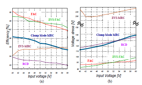
Figure 2: Comparison of efficiency and voltage stress in a forward converter
Texas Instruments (TI) has several ACF topologies to choose from, as shown in Table 1, the most popular of which are the LM5025A voltage mode and the UCC2897A current mode.
The LM5025A PWM controller contains all the functions required to implement a power converter using active clamp/reset technology. Using active clamp technology can achieve higher efficiency and higher power density compared to traditional capture winding or RDC clamp/reset techniques. Two control outputs are provided: main power switch control (OUT_A) and active clamp switch control (OUT_B). Two internal composite gate drivers parallel MOS and bipolar devices to provide superior gate drive characteristics. The controller is designed for high-speed operation, including an oscillator frequency range of up to 1MHz and a total PWM and current sense propagation delay of less than 100ns. The LM5025A includes a high-voltage startup regulator that operates over a wide input range of 13 V to 90 V. Other features include: line undervoltage lockout (UVLO), soft start, oscillator upper and lower synchronization functions, precise reference and thermal shutdown.
The UCC2897A is a peak current mode fixed frequency high performance pulse width modulator. The controller includes logic and drive capability for the P channel auxiliary switch, as well as a simple method to program critical delays for proper active clamping operation. Features include an internal programmable slope compensation circuit, precise D-MAX limiting, and a synchronized oscillator with internal timing capacitors. Accurate line monitoring also programs the on and off transitions of the converter based on the bulk input voltage VIN. The UCC2897A adds secondary hiccup mode current detection thresholds, bidirectional synchronization, and input overvoltage protection. The UCC2897A is available in 20-pin TSSOP (PW) and 20-pin QFN (RGP) packages.
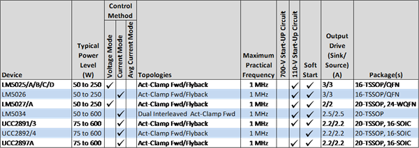
Table 1: Texas Instruments ACF devices
TI also offers over 79 active clamp TI Designs reference designs for free download. For example, the very popular Telecom Bus Converter Reference Design for Module Replacement (with seminar materials) is a 175W telecom ACF design (5V@35A) in a very small form factor with up to 95% efficiency and lower conduction losses than flyback.
The active clamp forward converter offers several key advantages and provides the best efficiency and lowest voltage stress among the presented forward topologies. It's okay to go a little further: get started with our active clamp design today.
- 1.2-36V 5A Adjustable Power Supply (Based on LM317)
- 0-28V 20A Adjustable Power Supply (Based on LM317 and 2N3055)
- Vehicle-mounted 12V to 50V DC converter
- Atmel solar panel battery charger
- Lead-acid battery charger circuit
- Battery reverse polarity protection circuit
- Should I choose voltage mode or current mode for fixed frequency pulse width modulation (PWM) control?
- Mitigating Overheating in Hyperscale and Ultra-Scale FPGA Applications
- Power Converter Topology Component Selection for High Input Voltage Applications
- How to simulate our buck converter control loop?
- Excellent performance household inverter power supply circuit
- Typical Reference Voltage and Power Supply Circuits
- Output 12V-10A power supply circuit
- 2-phase CPU power supply circuit using HIP6302 and HIP6602 chips
- 300A-18V three-phase thyristor voltage regulating electrolytic power supply circuit
- Household emergency power circuit
- Antenna amplifier synchronous power supply circuit
- Common power circuits and applications 04
- AC-DC conversion power supply-inverter power supply circuit
- Small power UPS power circuit and production


 京公网安备 11010802033920号