Driving circuit of TDA485X and TDA4841PS
Source: InternetPublisher:MartinFowler Keywords: Drive circuit Updated: 2025/07/11
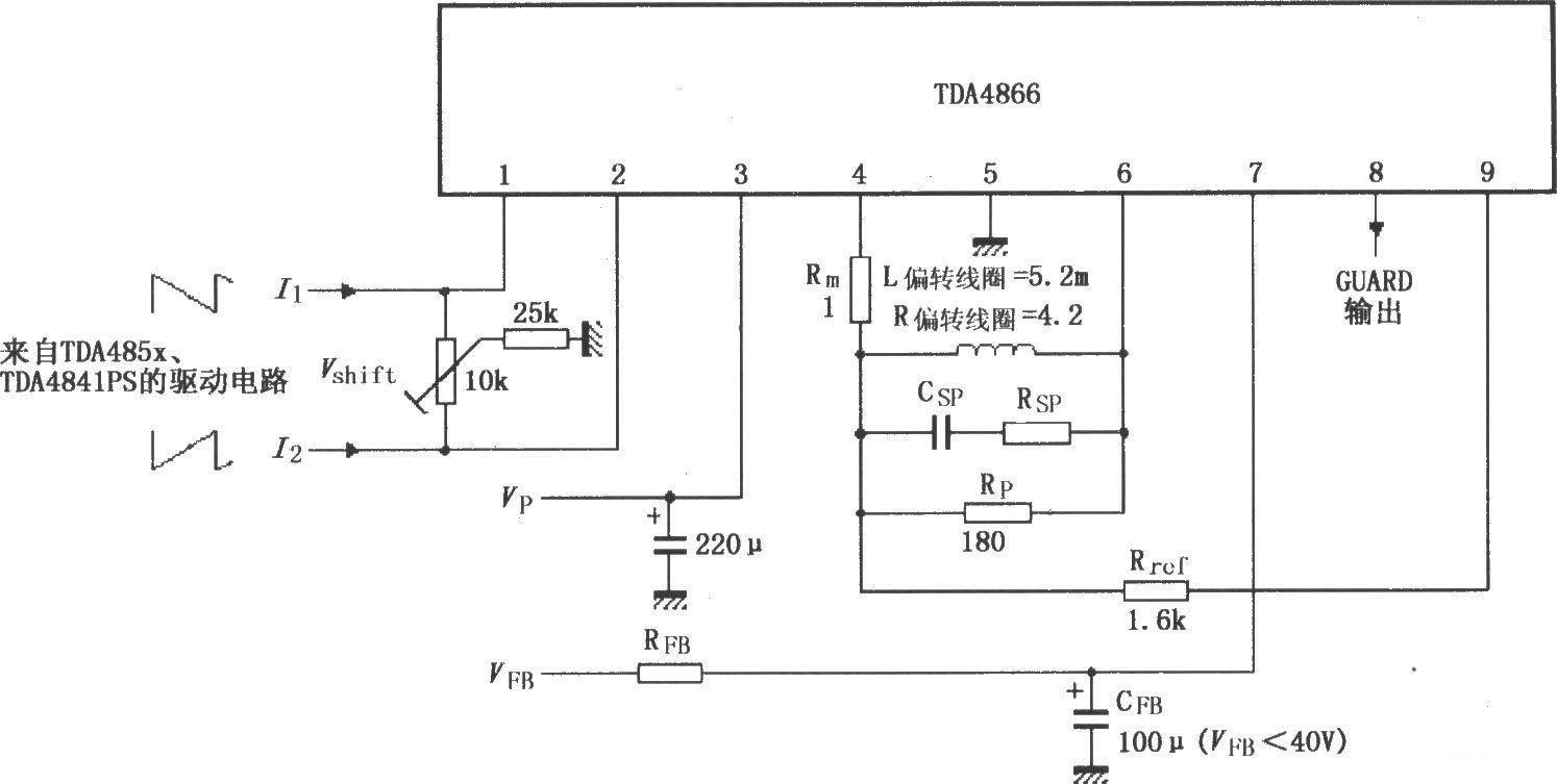
As shown in the figure, the driving circuit for TDA485X and TDA484lPS signals is composed of TDA4866. When the positive power supply voltage VP and the retrace power supply voltage VFB are added, the circuit starts to work. The input signal from the I2C bus automatic synchronization offset controller TDA4841PS (or TDA485X) monitored by the PC is input from pins 1 and 2 to the inverting input and non-inverting input of the internal differential input stage. The two internal vertical output stages form a full-bridge current drive output amplifier. After power amplification of the sawtooth wave signal, it is output from pins 6 and 4 to the deflection coil. The sawtooth wave current generates the deflection magnetic field required by the cathode ray tube through the deflection coil to control the electron beam to perform linear scanning. During the retrace period, the retrace generator supplies power to the vertical output stage, so that it has the minimum power consumption in the short retrace time, and at the same time, it is fed back to pin 9 through Rref. In three cases, pin 8 outputs a high-level protection signal: when the temperature is overheated, when the feedback loop works out of range, and during the retrace blanking period. The vertical output stage has temperature protection and coil short circuit protection (pins 4 and 6).
- TDA2030 - 14W Monolithic Power Amplifier
- 8W Class A amplifier
- 300W LM3886 Power Amplifier
- The Basics of Op Amp Loop Stability Analysis: Breaking the Loop
- 4 Steps to Reduce EMI When Designing with Darlington Relay Drivers
- Principle of multiplier voltage rectifier circuit
- Impedance transformation properties of ideal transformer
- Analysis of Several Constant Current Source Circuits Composed of Transistors and Operational Amplifiers
- Judgment of series feedback and parallel feedback
- Driving circuit of TDA485X and TDA4841PS
- Electronic control lock drive circuit
- Photoelectric control motor drive circuit
- Application of motor drive circuit in automatic tracking car model
- DC motor drive circuit schematic d
- Woodworking machine tool circuit a
- High performance DC power amplifier drive circuit AP500A-03
- LM621 brushless DC motor commutation circuit-three-phase half-wave drive circuit
- H-bridge drive circuit composed of Smart SIPMOS
- High-voltage board circuit composed of OZ9RR and push-pull drive circuit
- Excellent performance motor proportional drive circuit b


 京公网安备 11010802033920号