Transistor Tester
Source: InternetPublisher:桂花蒸 Keywords: Tester NE555 CD4027 transistor Updated: 2025/07/15
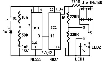
This simple circuit has been of great help to me in many cases. It can test the quality of transistors. In the circuit, with a resistance as low as 40 ohms between BC or BE, it can check the power output transistor in the amplifier circuit.
The circuit principle is as follows:
The 555 timer (IC1) works as a 12 Hz oscillator, and the output at pin 3 drives the 4027 (IC2) bistable circuit. After being divided by 2, the output is output at pins 14 and 15. The output is connected to LED1 and LED2 through the current limiting resistor R3. The two LEDs have been arranged so that only one LED will light up when transistors of different polarities are connected to the circuit. When no transistor is connected, the two LEDs will flash alternately. The outputs of pins 14 and 15 are connected to the B pole of the transistor under test through the voltage divider resistors R4 and R5. When a good transistor is connected, the transistor is turned on and a path is generated for one of the two LEDs. If a good NPN transistor is connected, LED1 will flash. If a PNP transistor is connected, LED2 will flash. If an open-circuited transistor is connected, the two LEDs will flash in turn. If a short-circuited transistor is connected, neither LED will flash.
- PIC Voltmeter
- Simple electromagnetic field probe
- Current sensor
- Digital AC voltmeter
- Frequency Logic Pen
- Auxiliary circuit for measuring small resistance
- Circuit solution for providing constant current load for testing battery
- Analog capacitance measuring instrument composed of CD4013
- Wideband Strain Gauge Signal Conditioner with Boosted Excitation Voltage
- Input bypass circuit with linearization (XTR112/XTR114)
- Detailed explanation of the working principle of linear regulated power supply
- Very simple voltage multiplier circuit block diagram
- Light-controlled street light circuit using NE555 (1)
- Use NE555 to make automatic telephone lighting
- Electric blanket cycle timer circuit
- Water tower automatic water supply control circuit
- Pocket LED reading light circuit composed of NE555
- Control circuit using NE555 integrated circuit_1
- Overvoltage and overcurrent protection circuit diagram using NE555
- Pulse width modulation switching regulated power supply circuit diagram composed of NE555


 京公网安备 11010802033920号