Introduction: This is a board designed based on the GC circuitry. While arranging the layout, I unexpectedly thought of adding point-to-point (PTP) pins.
Regarding the schematic and board: Because some components were designed by myself, the model isn't visible in the 3D preview. I'm a student, just starting my second year of high school, so I might not be able to reply to comments immediately, but I will answer every question. Since I've open-sourced it, I'm responsible for any problems others encounter during their DIY process. Any better suggestions are welcome. The schematic might not be the most aesthetically pleasing... but the board has been received and tested, so please use it with confidence (doge).
First, it's important to note that almost all the pads on this board require PTP pins to be screwed on first; components cannot be soldered directly. The pads requiring PTP pins are all 3mm in diameter.
You can find PTP pins by searching "PTP pins" on Taobao. Some are quite expensive (around 1 RMB each), the cheapest I found was 0.25 RMB each, although not as aesthetically pleasing as the more expensive ones. This picture shows a 0.25 each capacitor

; of course, you can buy others as well, as long as the diameter is 3mm. A total of 32 leveling screws are needed, so keep an eye on your wallet.
/************************************************* Regarding component selection ******************************************/
1. The filter capacitors on the board are compatible with 13mm and 16mm diameter capacitors. Just pay attention to this when purchasing. It's best not to buy too high a size, as it doesn't look good.
2. Input coupling capacitors are generally 2.2uf, but you can increase or decrease them depending on your preference. Just don't make them too big.
3. Decoupling capacitors can range from 22uf to 1000uf.
4. Basically, just don't make the components too big.
5. Be mindful of your budget.
/***********************Regarding cost*********************/
There isn't a precise figure. It depends on the components used. If you're using a free board (e.g., JLCPCB YYDS) and using lower-quality components, the cost will be around 50-60 (excluding heatsinks and transformers).
With better components, it could cost anywhere from 100 to over 100. It's not recommended to buy expensive mounting pins, as they can add up significantly to the cost. Generally, 70-80 watts is enough to make the board (excluding heatsink and transformer chassis).
/*Soldering Precautions*/
When soldering, set the soldering iron temperature high and don't use too low a wattage.
Please ensure good ventilation during soldering, as the smell will be strong. Also, pay attention to residual heat, especially on the jumper pins (don't ask me how I know).
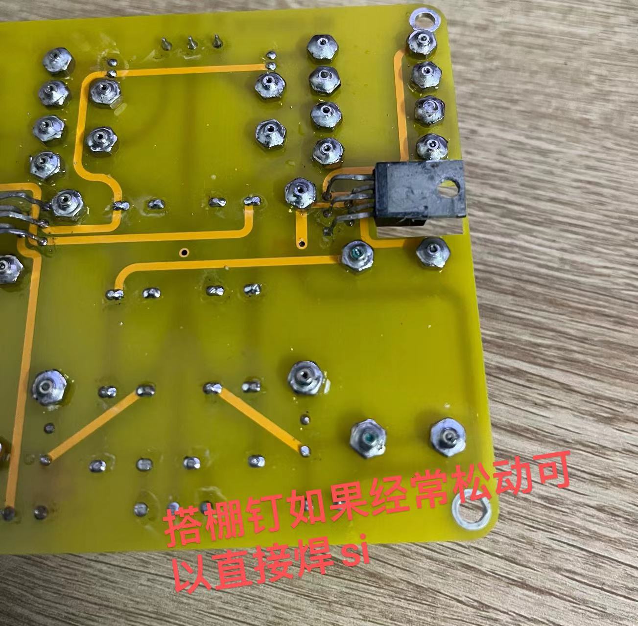
If the jumper pins aren't tight, you can solder them securely. You can also buy those that don't require screws for direct soldering.
Also, when soldering the 1875, be careful not to bridging the leads or leaving any gaps in the solder.
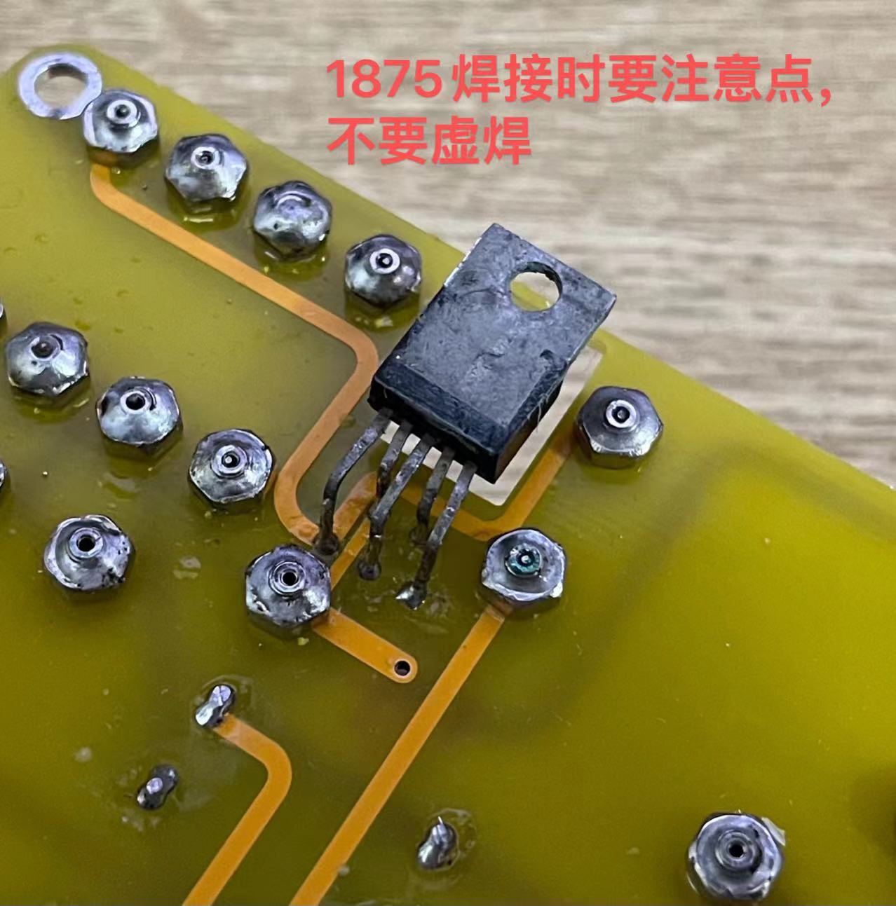
A very important point when soldering the 1875 is to raise the leads high! If they are too low, the jumper pins will touch the heatsink. This is extremely important!!!

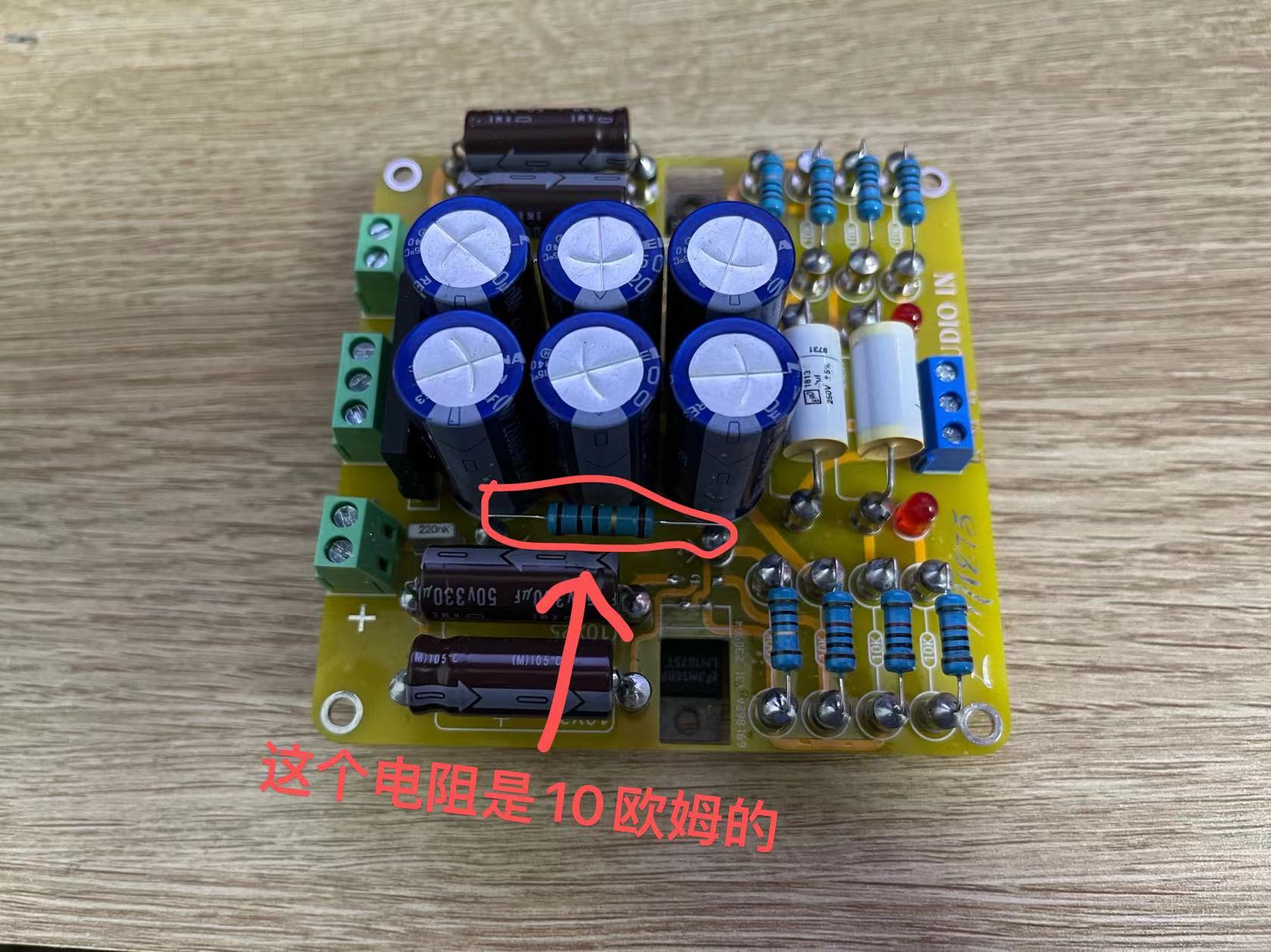
Another point is that the enclosed resistor is actually 10 ohms.
/************************************************************ Final Stage: Check and Power-On Test *****************************************************/
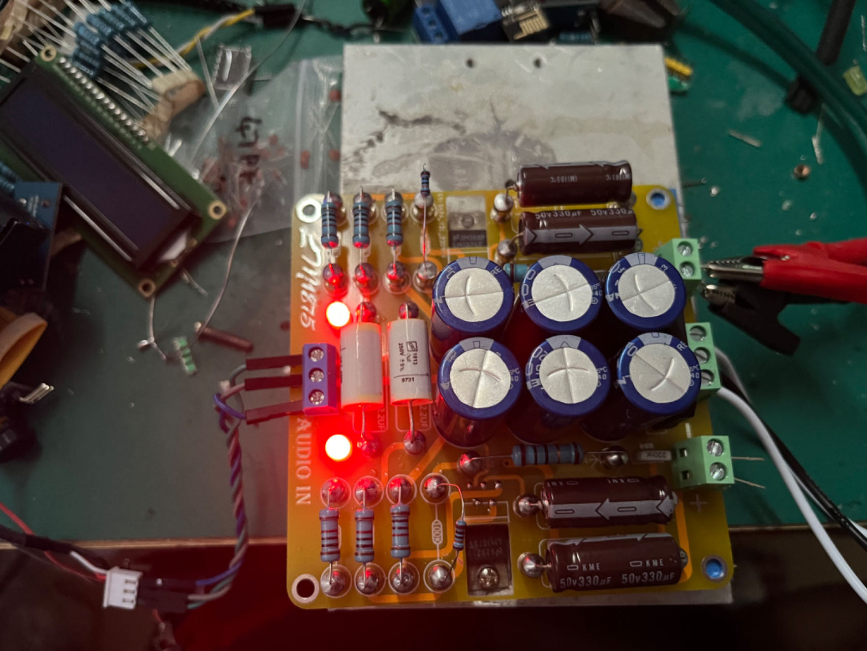
After the components are soldered correctly without any missing solder joints, you can proceed with the power-on test. If possible, use a low-voltage transformer for the test, and remember to install a heatsink.
@@@@@@@@@@@ After powering on, do not connect the speaker or audio input yet, just connect the transformer. After powering on, both power indicator lights will light up. If this is OK, there should
be no problems.
@@@@@@@@@@@ Then connect the speaker and power it on. The speaker should have no hum or background noise at this point. Then touch the "L" or "R" pin on the audio input.
The speaker should make a "hissing" sound when touched (this is hard to describe, but if you hear a sound, that's correct). Test both channels. If this passes, it means there are basically no problems, and you can
connect speakers to test it. Also, pay attention to whether there is any hum or background noise. There shouldn't be any background noise. When I tested it, I could barely hear it unless I put my ear right up to the speaker (
I mean, the background noise was almost zero).
When connecting the audio source, I recommend using a Bluetooth module. It's best not to connect devices like mobile phones first.
After passing the test, you can choose to match it with your case or other components.
This is a picture of my final soldered result.
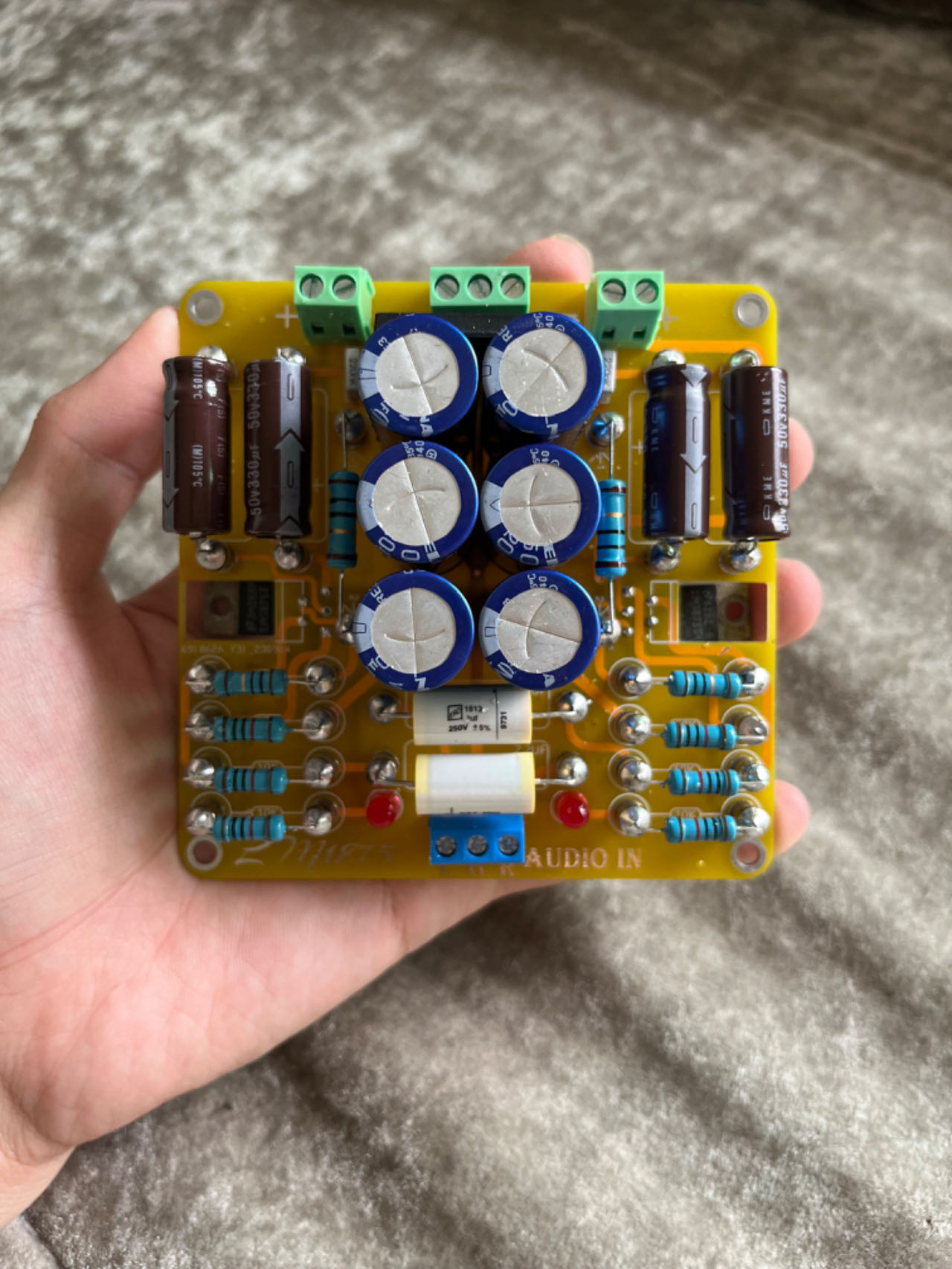
This picture is of the previous version; this board is an improvement on that (the previous version had too thin wiring, haha). Finally, if you find any problems or design flaws in the schematic, PCB, or other aspects, please leave a message to let me know. Thank you. You can also discuss any issues you encounter

during soldering or debugging. October 14, 2023


 京公网安备 11010802033920号

 AFL27015DWCH


