The MAX1132 is a 200ksps, 16-bit ADC. The MAXQ2000 can interface with the MAX1132 using different clock modes: 8-bit, 16-bit, or a combination of both. To optimize ADC performance, it is important to decide which mode to use during the initial stages of development. Obviously, a 16-bit ADC with 16 clock cycles per frame should be in 16-bit mode; however, in the specific case of an ADC with 24 clock cycles per frame, the SPI clock mode must be carefully evaluated. This application note provides test results using 8-bit, 16-bit, and a combination of the two modes. According to the results, it can be seen that when the MAX1132 uses a 24-clock frame format, the best performance can be obtained by using the combination mode.
This application circuit is implemented using the MAX1132 evaluation board and the MAXQ2000 evaluation board.
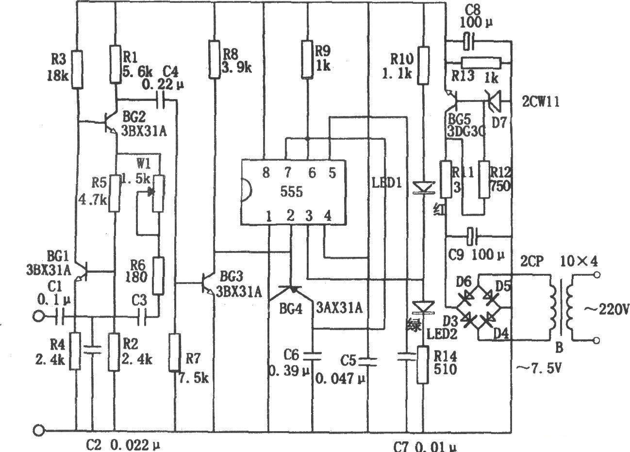
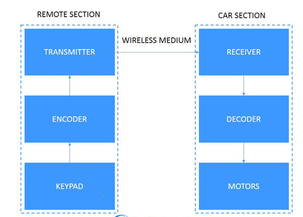
Figure 1 shows the MAX1132 evaluation board schematic, and Figure 2 shows the system configuration. To connect the MAX1132 EV kit to the MAXQ2000 EV kit, connect the SCLK, /CS, DOUT, and DIN pins on the MAX1132 EV kit to the MAXQ2000 EV kit, as shown in Figure 2. In addition, connect a +5V power supply to the AV DD and AGND ports on the evaluation board . JU1 of the evaluation board must be installed in the 1–2 (ON) position. Connect the analog signal up to +12V on JU2 and leave the other jumpers open. To ensure proper system operation, SW3 of the MAXQ2000 evaluation board must be turned off.
Figure 1. MAX1132 Evaluation Kit Schematic
All reference designs on this site are sourced from major semiconductor manufacturers or collected online for learning and research. The copyright belongs to the semiconductor manufacturer or the original author. If you believe that the reference design of this site infringes upon your relevant rights and interests, please send us a rights notice. As a neutral platform service provider, we will take measures to delete the relevant content in accordance with relevant laws after receiving the relevant notice from the rights holder. Please send relevant notifications to email: bbs_service@eeworld.com.cn.
It is your responsibility to test the circuit yourself and determine its suitability for you. EEWorld will not be liable for direct, indirect, special, incidental, consequential or punitive damages arising from any cause or anything connected to any reference design used.
Supported by EEWorld Datasheet
EEWorld
subscription
account

EEWorld
service
account

Automotive
development
community

Robot
development
community

About Us Customer Service Contact Information Datasheet Sitemap LatestNews


Room 1530, 15th Floor, Building B,
No.18 Zhongguancun Street,
Haidian District,
Beijing, Postal Code: 100190
China
Telephone: 008610 8235 0740
 京公网安备 11010802033920号

 1200CGG1504B3NB