Modern logic systems powered by 3.3V power supplies sometimes run in industrial environments and may require ±10V voltage drives, such as PLCs , transmitters, motor controls, etc. One way to meet this need is to choose a DAC that can provide a voltage swing of ±10V, but a better approach is to use a 3.3V DAC and then amplify its output to ±10V for the following reasons:
3.3V DACs have higher logic integrity than ±10V DACs.
The 3.3V DAC has a higher-speed logic interface, which can free up some tasks from the microcontroller to handle other tasks.
The DAC may be integrated into a large-scale, 3.3V powered chip (such as a microcontroller) and cannot provide a ±10V output swing.
The external load may require a certain output current drive, or drive a capacitive load, and a ±10V DAC cannot meet this requirement.
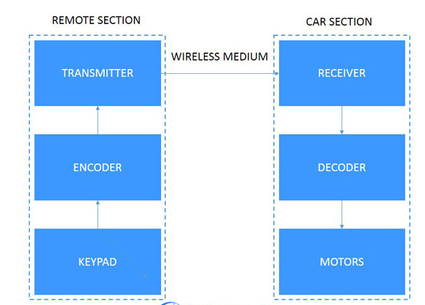
The circuit block diagram is shown in Figure 1a (see the Details tab) and contains five main parts: DAC , reference source, bias adjustment, reference source buffer and output buffer.
The DAC provides digital-to-voltage conversion relative to a reference point voltage. The bias circuit adjusts the DAC's unipolar transfer function to produce a bipolar output and calibrates the 0V output point. The reference buffer provides load isolation and offset regulation for the reference source. The output buffer adds the bias voltage to the signal and provides the required gain so that the output swings to the desired level. In addition, the output buffer also provides certain load driving capabilities.
All reference designs on this site are sourced from major semiconductor manufacturers or collected online for learning and research. The copyright belongs to the semiconductor manufacturer or the original author. If you believe that the reference design of this site infringes upon your relevant rights and interests, please send us a rights notice. As a neutral platform service provider, we will take measures to delete the relevant content in accordance with relevant laws after receiving the relevant notice from the rights holder. Please send relevant notifications to email: bbs_service@eeworld.com.cn.
It is your responsibility to test the circuit yourself and determine its suitability for you. EEWorld will not be liable for direct, indirect, special, incidental, consequential or punitive damages arising from any cause or anything connected to any reference design used.
Supported by EEWorld Datasheet
EEWorld
subscription
account

EEWorld
service
account

Automotive
development
community

Robot
development
community

About Us Customer Service Contact Information Datasheet Sitemap LatestNews


Room 1530, 15th Floor, Building B,
No.18 Zhongguancun Street,
Haidian District,
Beijing, Postal Code: 100190
China
Telephone: 008610 8235 0740
 京公网安备 11010802033920号

 160683630H-F