To ensure compliance with all international standards, the designer of an isolated power supply for telecom applications needs to take certain facts into account: The input voltage is never 110V or 220V from the mains, but the lower voltage of a lead-acid battery (-12V, -24V, or -48V) that is charged by means of the mains through rectification (Figure 1). (Batteries back up the telecom system in case of failure in the mains supply.) To combat corrosion due to ion flow, the input voltage is always negative, with the positive terminal connected to ground.
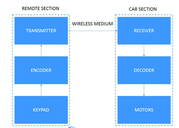
Figure 1. In this block diagram of the backup architecture used in telecom systems, a battery block is kept charged by the mains rectifier. In the event of a mains failure, it supplies the system to prevent transmission interruptions.
All reference designs on this site are sourced from major semiconductor manufacturers or collected online for learning and research. The copyright belongs to the semiconductor manufacturer or the original author. If you believe that the reference design of this site infringes upon your relevant rights and interests, please send us a rights notice. As a neutral platform service provider, we will take measures to delete the relevant content in accordance with relevant laws after receiving the relevant notice from the rights holder. Please send relevant notifications to email: bbs_service@eeworld.com.cn.
It is your responsibility to test the circuit yourself and determine its suitability for you. EEWorld will not be liable for direct, indirect, special, incidental, consequential or punitive damages arising from any cause or anything connected to any reference design used.
Supported by EEWorld Datasheet
EEWorld
subscription
account

EEWorld
service
account

Automotive
development
community

Robot
development
community

About Us Customer Service Contact Information Datasheet Sitemap LatestNews


Room 1530, 15th Floor, Building B,
No.18 Zhongguancun Street,
Haidian District,
Beijing, Postal Code: 100190
China
Telephone: 008610 8235 0740
 京公网安备 11010802033920号

 070922FR015S401CY