| Component | IDD Value at 25°C |
IDD Value at 85°C |
| ADuC7060/ADuC7061 ADC0 On, Gain = 32, FADC = 100 Hz CPU speed = 640 kHz (POWCON0 = 0x7C) PWM On. PWMCON1 = 0x100 External reference selected by ADC0. All other peripherals off. Note: Add excitation current value to this figure . Typical value is 200 µA. |
2.45 mA 0.2 mA |
2.74 mA 0.2 mA |
| ADR280, 1.2 V Reference | 12 µA | 15 µA |
| ADP1720, 2.5 V Output Linear Regulator | 200 µA 3 | 300 µA |
| OP193, Low Power Op Amp | 15 µA | 25 µA |
| Remaining Circuitry | 50 µA | 50 µA |
| Total Current Less Excitation Current | 2.73mA | 3.13mA |
The DNL plot in Figure 2 shows that DNL is typically better than 0.6 LSB over the critical 4 mA to 20 mA range. These tests employ a second-order filter at the PWM output and use two 47 kΩ resistors and two 100 nF capacitors, as shown in Figure 1.

The performance of the PWM output can be enhanced by using the ADC to measure the voltage at point V R12 and other points in the circuit. This feedback method can be used to calibrate the PWM output to provide higher accuracy.
Note that the PWM circuit is only used to set the output voltage in the range of 0 V to 600 mV, so the code count is reduced. Codes above 0 represent values greater than 24 mA and are therefore irrelevant.
For ADC measurement performance, please refer to the AN-970, CN-0075, and ADuC7060/ADuC7061 data sheets.
Table 2. Typical IDD Values for Different Peripherals on the ADuC7060/ADuC7061
| Peripheral of ADuC7060/61 | DD Value, Typical, 25°C |
| ARM7 Core @ 10.24 MHz 5.12 MHz 2.56 MHz 1.28 MHz 640 kHz 320 kHz 160 kHz 80 kHz |
5.22 mA 4.04 mA 2.7 mA 2 mA 1.674 mA 1.5 mA 1.42 mA 1.38 mA |
| Primary ADC, G = 1 G = 4 G ≥ 128 |
30 µA 440 µA 630 µA |
| Auxiliary ADC | 350 µA |
| DAC | 330 µA |
| PWM | 340 µA |
| SPI | 40 µA |
| UART | 200 µA |


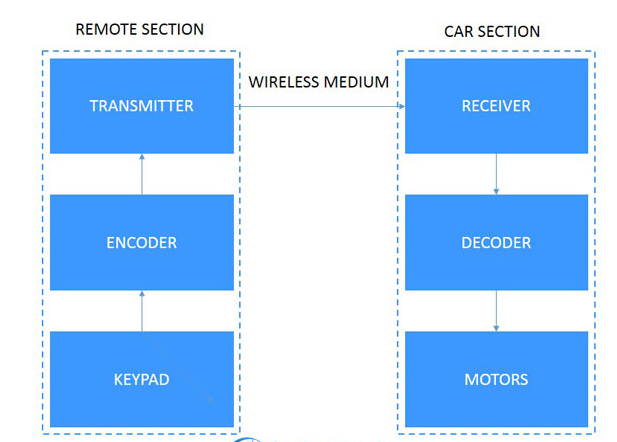
Blockdiagram
All reference designs on this site are sourced from major semiconductor manufacturers or collected online for learning and research. The copyright belongs to the semiconductor manufacturer or the original author. If you believe that the reference design of this site infringes upon your relevant rights and interests, please send us a rights notice. As a neutral platform service provider, we will take measures to delete the relevant content in accordance with relevant laws after receiving the relevant notice from the rights holder. Please send relevant notifications to email: bbs_service@eeworld.com.cn.
It is your responsibility to test the circuit yourself and determine its suitability for you. EEWorld will not be liable for direct, indirect, special, incidental, consequential or punitive damages arising from any cause or anything connected to any reference design used.
Supported by EEWorld Datasheet
EEWorld
subscription
account

EEWorld
service
account

Automotive
development
community

Robot
development
community

About Us Customer Service Contact Information Datasheet Sitemap LatestNews


Room 1530, 15th Floor, Building B,
No.18 Zhongguancun Street,
Haidian District,
Beijing, Postal Code: 100190
China
Telephone: 008610 8235 0740
 京公网安备 11010802033920号

 MC68HC711L6MFU