1. Project Function Introduction:
This desktop environmental monitoring project uses the LCSC Liangshanpai development board as the main control core and the FreeRTOS real-time operating system to achieve modular task execution. Each task runs independently without affecting others. It aims to create a desktop environmental monitoring instrument with built-in high-precision temperature and humidity sensors, specifically the Sensirion SHT30 temperature and humidity sensor, for monitoring indoor temperature and humidity. A three-in-one VOC/CO2/CH2O gas sensor is used to monitor indoor air quality and detect formaldehyde. The control unit uses an infrared transmitting module to control home appliances and electronic products (requires a built-in infrared module). Simultaneously, it connects to Wi-Fi to obtain regional weather information and can connect to a cloud platform to upload data. Users can view and control home appliances and electronic products in real time on a mobile phone. This project not only meets indoor environmental monitoring needs but also serves as a desktop decorative item. The display uses a 4.3-inch RGB interface screen with LVGL to achieve real-time display of monitoring data and human-computer interaction.
2. Introduction to Functional Module Circuits
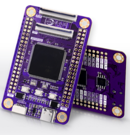
1. LCSC Liangshanpai Core Board
LCSC Liangshanpai Development Board is a fully domestically produced open-source development board based on the GD32F450ZGT6. It boasts rich resource interfaces and comprehensive supporting video tutorials, documentation tutorials, and experimental cases. An online compiler is provided for a quick 10-minute introduction. Its open-source design makes it suitable for beginners and project evaluation.
2. Temperature and Humidity Sensor Module
The temperature module uses the SHT30, manufactured by the Swiss sensor manufacturer Sensirion. This digital temperature and humidity sensor accurately measures ambient temperature and humidity, featuring low power consumption, high accuracy, and a wide range of applications. The SHT30 sensor plays an important role in smart homes, industrial automation, weather stations, and other fields, and is widely used in various electronic devices and systems. This sensor has a wide power supply voltage range, from 2.15 V to 5.5 V, uses an I2C interface with a communication speed of up to 1MHz and two user-selectable addresses, with typical accuracy of ±1.5% relative humidity and ±0.1°C.
When using the Liangshanpai driver for the SHT30 sensor, because the SHT30 sensor is an I2C bus device, it requires the I2C communication protocol during operation. Therefore, during the design process, a 4.7kΩ pull-up resistor needs to be added to both the clock and signal lines to ensure the stability and reliability of the signal lines during signal transmission on the I2C bus, avoiding interference and data errors, and ensuring the accuracy of data transmission.

3. The gas sensor module
uses a TVOC-CO2 three-in-one air quality monitor to measure indoor air quality. This module can detect the following gases: ammonia, hydrogen, alcohol, carbon monoxide, carbon dioxide, methane, formaldehyde, and other volatile organic compounds; smoke from cigarettes, burning wood and paper, and cooking fumes. Sensitivity reaches 0.1ppm for hydrogen, and the measurement range is: Total Volatile Organic Compounds (TVOC): 0-2.000mg/m³, Carbon Dioxide (CO2): 350-2000pp (analog value), Formaldehyde (HCHO): 0-1.000mg/m³. The module outputs data via UART (5V level), and this product's output data is connected to the Liangshanpai UART4 peripheral.
Module features: zero-point calibration, three-in-one data output, high sensitivity, long lifespan, low power consumption, automatic calibration, built-in temperature and humidity compensation, UART serial port signal output, and simple application.
Commonly used in vehicle and home air purifiers, multi-functional air quality monitors, portable multi-functional air quality testers, etc.

4. Infrared Module: The
infrared learning module, as the name suggests, uses infrared light as its communication medium and a carrier frequency of 38kHz. Working principle: The user sends commands to the infrared learning module's serial port to put the module into internal or external memory learning mode. When a user presses a button on the remote control, the module receives the infrared encoded data and stores it in the chip's internal Flash memory or sends it out via serial port according to the protocol. When the user sends a command to the module's serial port to retrieve the encoded data stored internally or directly sends encoded data to the module via serial port, the module modulates the encoded data onto a 38kHz infrared carrier wave and transmits it through the infrared transmitter, thus controlling home appliances. The currently tested effective distance is approximately 5-8 meters. It currently supports learning and forwarding the button codes of 99% of infrared remote controls on the market, including air conditioners, televisions, set-top boxes, and fans.
Module features: This infrared learning module supports baud rate setting and querying, module address setting and querying, internal and external storage of infrared remote control codes, sending internal and external stored codes, automatic sending of internal stored codes upon power-on, reading and writing of internal infrared codes, reset and formatting, and many other functions. Operating voltage: 3.3~5V (5V power supply is optimal), operating current: 5~30mA, infrared carrier frequency: 38KHz, remote control distance: 5~8 meters, communication interface: TTL.
This project uses Liangshanpai's USART2 for infrared code transmission. Before transmission, the infrared remote control code encoding of the target product needs to be learned. The encoded data is sent directly to the module via serial port by retrieving the encoded data stored internally.

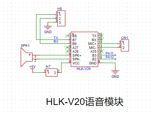
5. HLK-V20 Voice Module
The HLK-V20 is a high-performance pure offline voice recognition module launched by Hailing Technology Electronics for a large number of pure offline control scenarios and products. It can be widely and quickly applied to smart homes, various smart small appliances, 86-type set-top boxes, toys, lighting fixtures, industrial, medical, IoT, automotive, security and lighting products that require voice control. The HLK-V20 supports offline recognition of 150 local commands, and the wake-up words, command words and response broadcast words can be freely customized. It has rich peripheral interfaces.
The voice recognition module allows us to freely design command words, which can be configured through an online configuration platform. After configuration, a voice recognition firmware will be generated. We need to download the firmware to the module via pins B6 and B7. Therefore, pins B6 and B7 are brought out via headers below for easy downloading. It's important to note that the module must be powered off before downloading the firmware. Power should only be applied after the download tool recognizes the module for successful downloading. This power-on/off operation is controlled by the CN1 jumper in the schematic.
6. ESP8266-12F Module
ESP8266: The ESP8266 is a low-cost Wi-Fi chip developed by Espressif Systems. It integrates a processor, Wi-Fi module, memory, and other peripherals. The ESP8266 chip communicates with other devices (such as microcontrollers) via a serial interface (such as UART or SPI) and provides connectivity and communication capabilities with Wi-Fi networks.
ESP-12F: The ESP-12F is a specific module model in the ESP8266 series. It is a module based on the ESP8266 chip, containing the ESP8266 chip itself and additional external components such as antennas, power management circuits, and pinouts. The ESP-12F module is characterized by its small size, compact design, and numerous pins, allowing it to be directly soldered onto the PCB.
In this design, the ESP8266-12F is used for data upload to the cloud platform and to obtain real-time regional weather. Its internal TX, RX communication pins, reset pin, and IO0 pin for setting the mode are brought out for later firmware flashing.

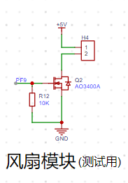
7. Fan Module:
This module is mainly used for simulation testing.
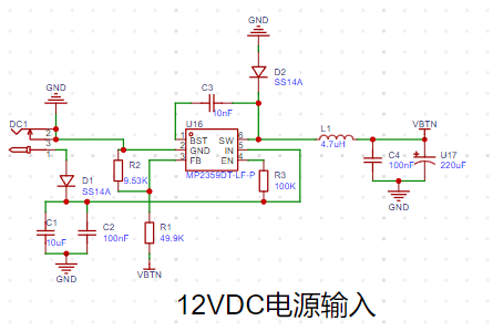
8. Power Supply Section:
The 12VDC power input circuit can be omitted to save on circuit costs, allowing the entire system to operate normally. (Type-C connection required). The
+5V and +3.3V power supply circuits in this project use MP2359 and AMS1117-3.3 chips.
The MP2359 is a monolithic buck switching converter with an integrated power MOSFET. It provides a peak output current of 1.2A over a wide input range, exhibiting excellent load and linear regulation. Current control mode provides fast transient response and makes the loop easier to stabilize.
The MP2359 operates from 4.5V to 24V with a wide input voltage range and an adjustable output range of 0.81V to 15V.
This design references the MP2359 datasheet (official English version) for a 12V-to-5V voltage conversion. The datasheet provides a classic example of implementing 12V-to-5V buck operation and its peripheral circuit design. Here, I've added a switch control for external power input when the DIP switch is on.
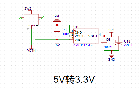
For cost savings, this 5V-to-3.3V circuit can operate without being soldered to power the entire system. (Type-C connection required)
The AMS1117-3.3 is a 3.3V output low-dropout regulator suitable for high-efficiency linear regulators, switching power supply regulators, battery chargers, active small computer system interface terminals, and power management batteries for laptop power supplies.
AMS1117-3.3 output voltage range: 3.201V~3.399V; accuracy: 1%.
The circuit from left to right shows the input, ground, and output. After regulating 12V to 5V, VBTN is connected to the chip's +5V input network. C5 and U18 are output filter capacitors used to suppress self-oscillation. If these two capacitors are not connected, the linear regulator's output will typically be an oscillating waveform.
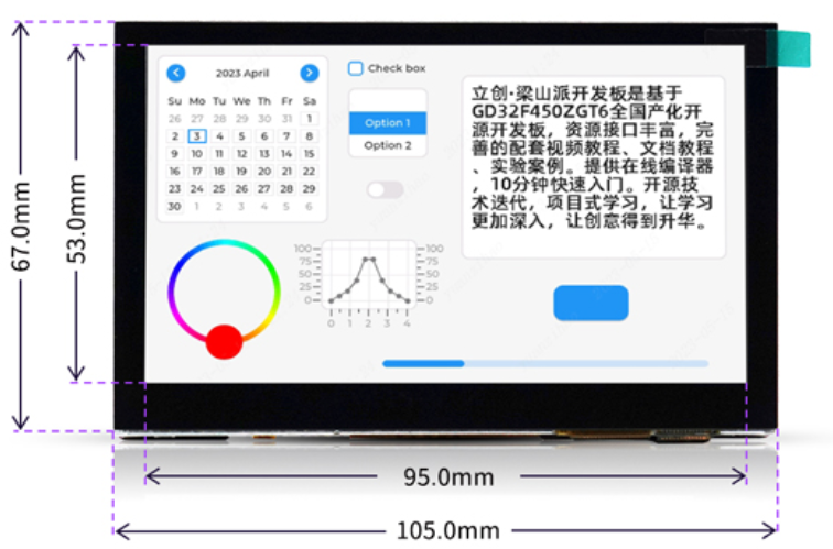
9. LCSC 4.3 RGB interface screen
: The screen is used for real-time data display and human-computer interaction.
10. Pin Selection
: Analysis of the screen documentation reveals that the 4.3 RGB interface screen primarily connects to HSYNC (PC6), VSYNC (PA4), PCLK (PG7), DE (PF10), LCD_R7 (PG6), LCD_R6 (PA8), LCD_R5 (PA12), LCD_R4 (PA11), LCD_R3 (PB0), LCD_G7 (PD3), LCD_G6 (PC7), LCD_G5 (PB11), LCD_G4 (PB10), LCD_G3 (PG10), LCD_G2 (PA6), LCD_B7 (PB9), LCD_B6 (PB8), LCD_B5 (PA3), LCD_B4 (PG12), and LCD_B3 (PG11). Since we cannot reuse other functions on these pins, we need to find other pins with special functions. Based on the datasheet, the following pins are selected:
ESP8266-12F: Serial Port Number: USART1 Pins: PD5 (TX) PD6 (RX) Multiplexed: GPIO_AF_7

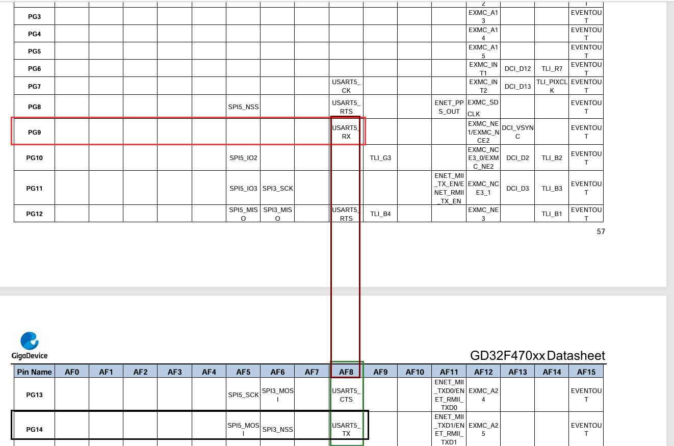
HLK-V20 Voice Module: Serial Port: USART5 Pins: PG14 (TX) PG9 (RX) Multiplexed: GPIO_AF_8
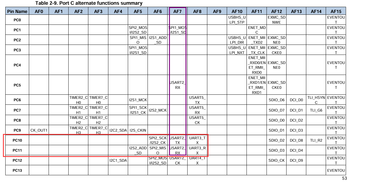
Infrared Module: Serial Port: USART2 Pins: PC10 (TX) PC11 (RX) Multiplexed: GPIO_AF_7
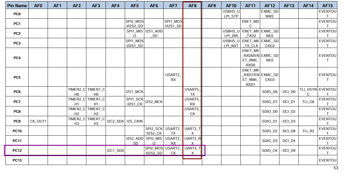
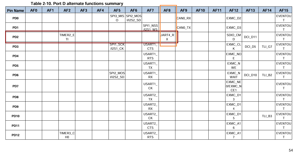
Gas Sensor Module: Serial Port: UART4 Pins: PC12 (TX) PD2 (RX) Multiplexed: GPIO_AF_8
Temperature and Humidity Sensor Module: SDA: PB7 SCL: PB6
3. Software Introduction
1. FreeRTOS
This design uses a real-time operating system software design. Employing an embedded real-time operating system (RTOS) allows for more rational and effective utilization of CPU resources, simplifies application software design, shortens system development time, and better ensures system real-time performance and reliability. FreeRTOS is a completely free operating system with open source code, portability, customizability, and flexible scheduling strategies, making it easily portable to various microcontrollers.
The FreeRTOS API is used for task management, memory management, time management, interrupt handling, and other operations. The system divides time into many time slices and then executes each task in turn. Each task runs independently and does not affect others.
There are many FreeRTOS porting processes online, so they will not be described in detail here.

2. LVGL
This design uses LVGL, an open-source embedded graphics library that provides rich graphics components and animation effects to help developers implement beautiful user interfaces on embedded devices. LVGL is cross-platform and supports multiple operating systems and microcontroller architectures, so it is widely used in various embedded devices, such as smart home products, industrial control equipment, and medical devices. LVGL also provides rich documentation and sample code to help developers quickly get started and customize their own interface styles.
This design uses LVGL version 8.2.
There are many LVGL porting processes online, so they will not be described in detail here.

3. Xinzhi Weather
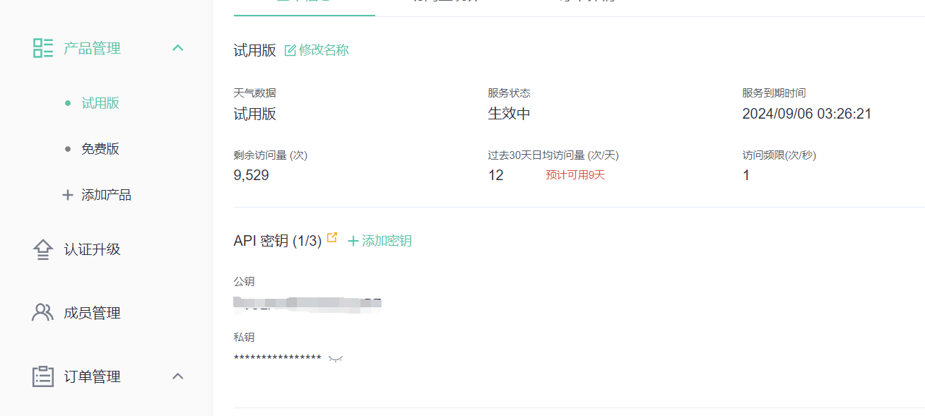
This design uses the Xinzhi Weather API (https://www.seniverse.com/) to obtain weather information. After registering, select a version; for demonstration purposes, a 14-day trial version is used.

Remember the product's API key. Click on Product Management, then Click on Trial Version.
Next, we need to obtain the API interface to retrieve data. Open the product documentation, select Real-time Weather, and click on the blue Real-Time Weather

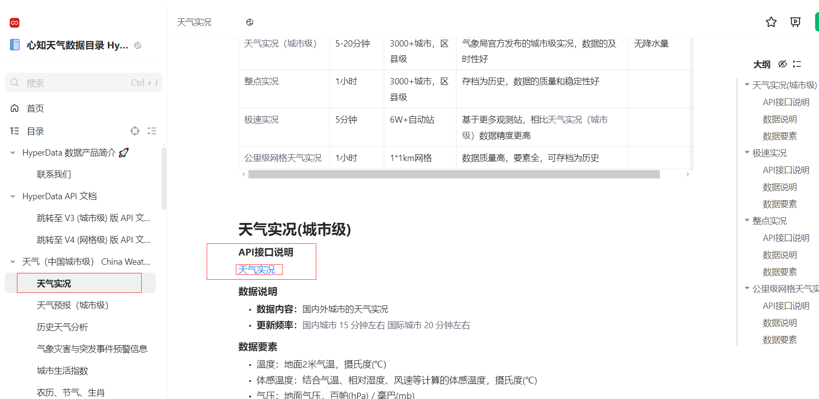
API address. This is our API interface. Change the black box "your_api_key" to your own API key.
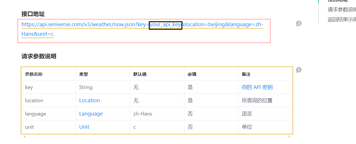
Test in the browser to see if we can retrieve the correct information.
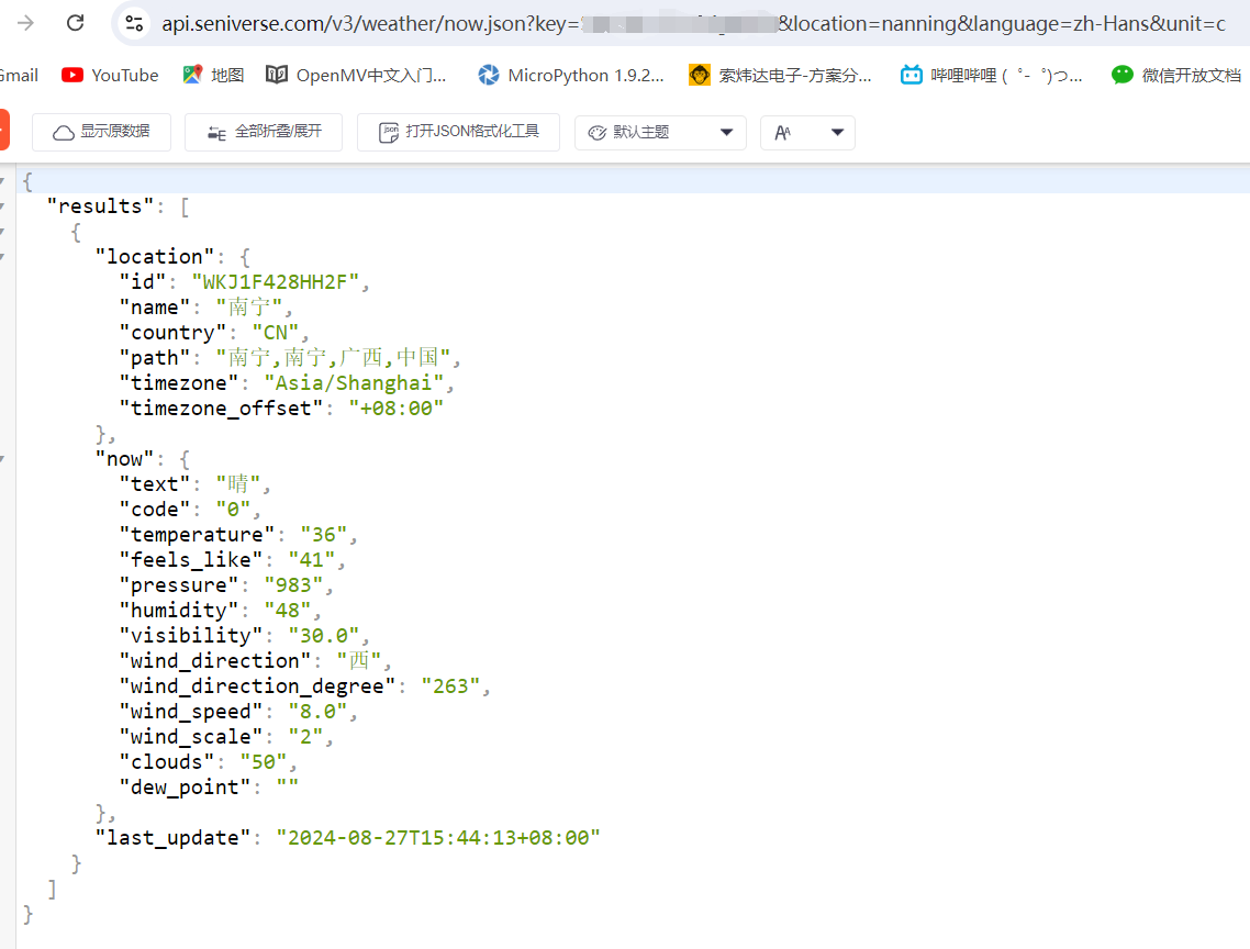
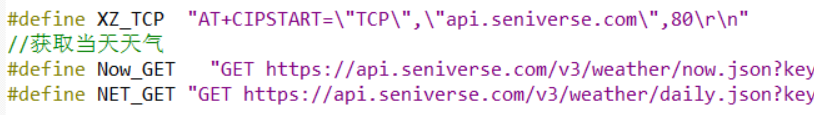
Then we can put the API interface into the program and let the ESP8266 retrieve weather data.
4. Function Interface Introduction
4.1 Boot Interface
After the boot progress bar animation completes, you will enter the password input interface.


Enter the password correctly to enter the main interface.
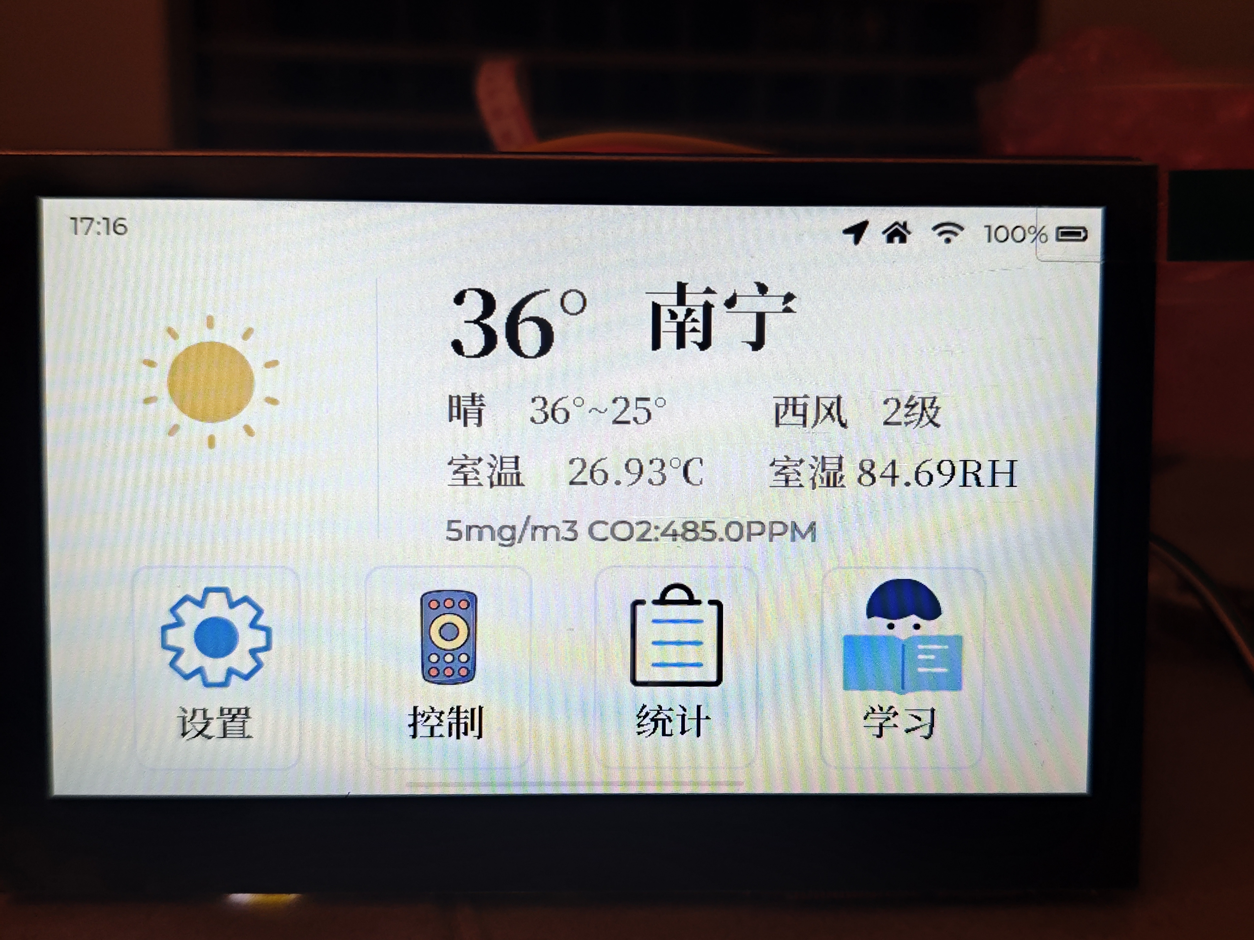
4.2 Main Interface
The main interface consists of three tiled views: the first is the five-day weather forecast, the second is the main interface, and the third is the air conditioning control interface.
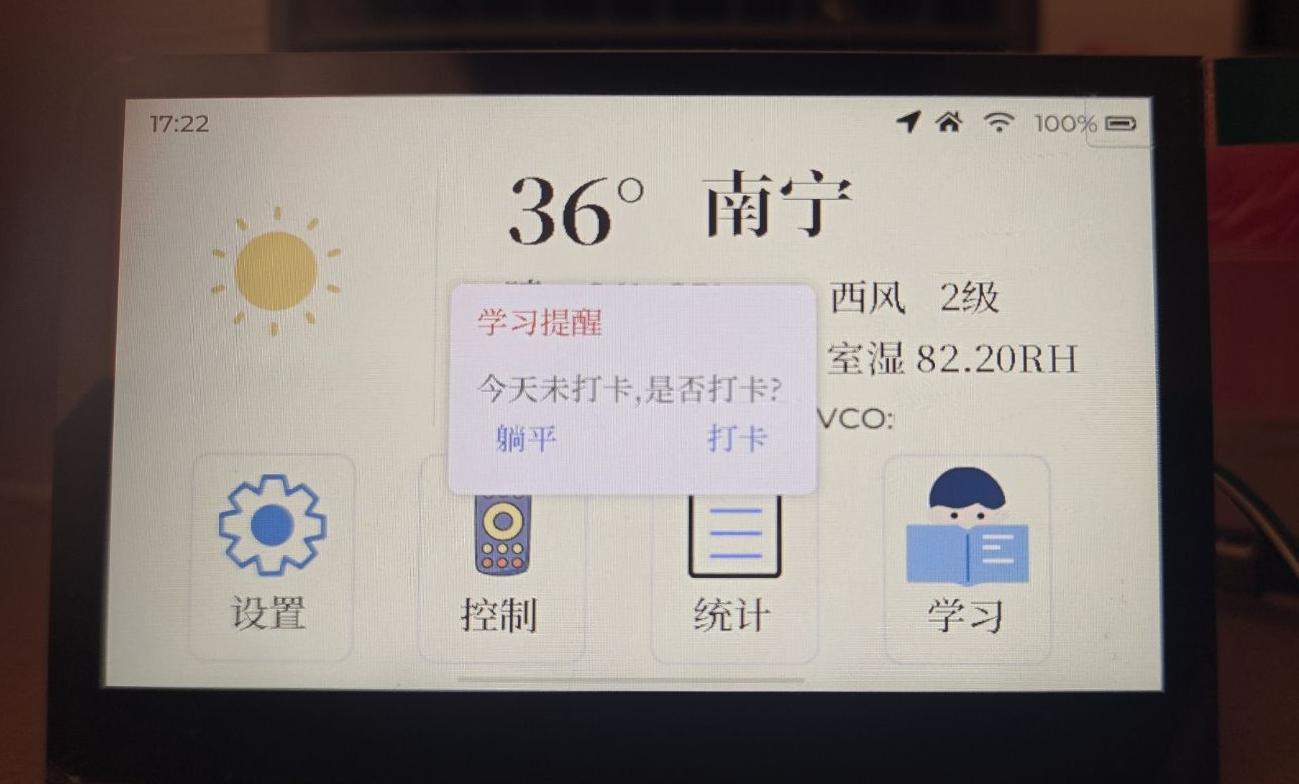
Main Interface: Displays time, weather phenomenon icons, weather phenomenon text, outdoor temperature, maximum and minimum temperatures, wind direction, wind force level, indoor temperature and humidity, indoor air concentration, and four image control buttons.
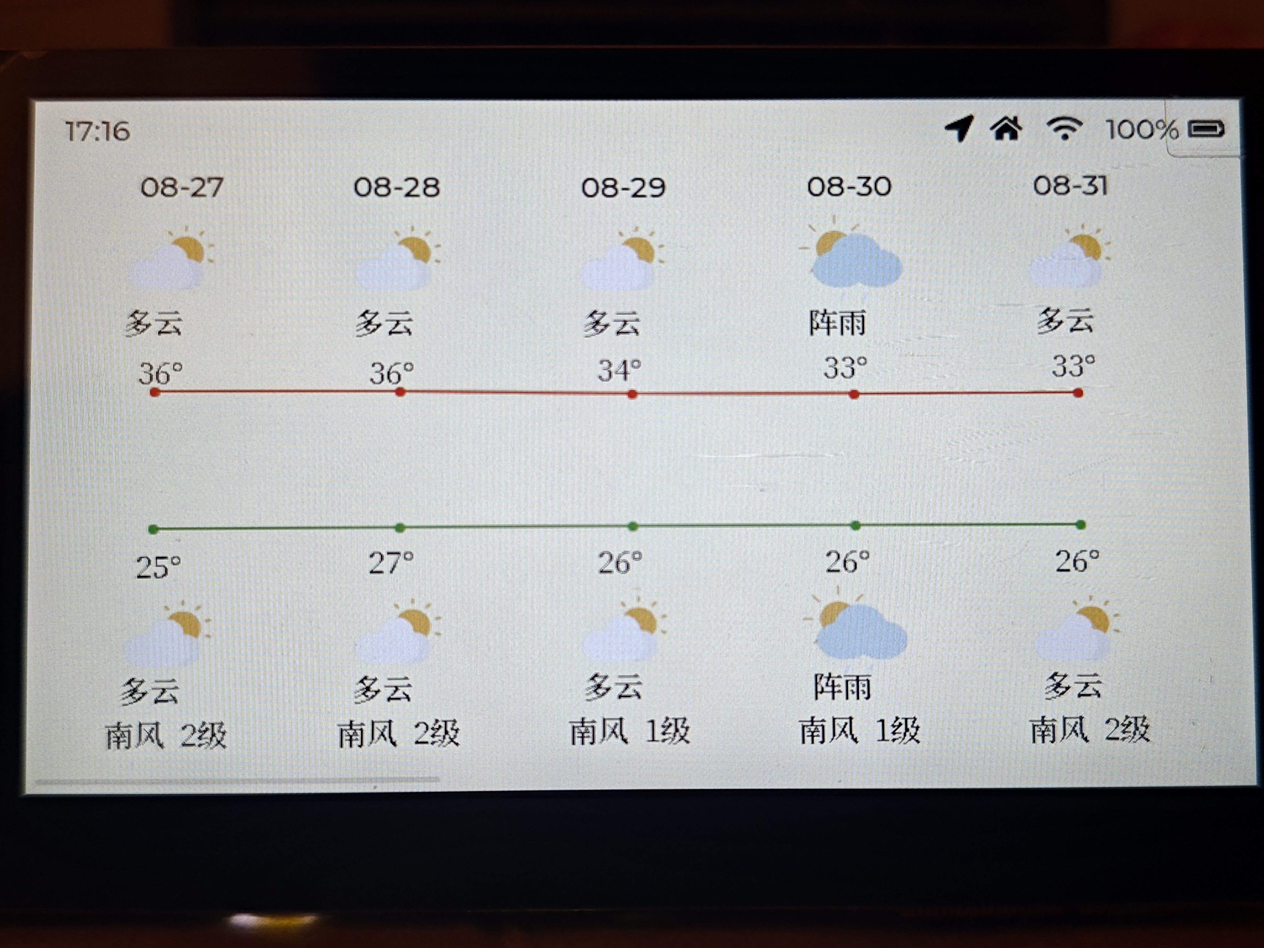
Weather Forecast: Includes date, weather phenomenon icons, weather phenomenon text, maximum and minimum temperatures, wind direction, and wind force level.
Air Conditioning Control Interface: Implemented using a button matrix component. Pressing - or + will adjust the temperature.

4.3 Learning Interface
: Clicking on the learning interface will prompt you to check in if you haven't done so for the day. Selecting OK will successfully check in. Once checked in for the day, you cannot check in again.


4.4 Statistics Interface:
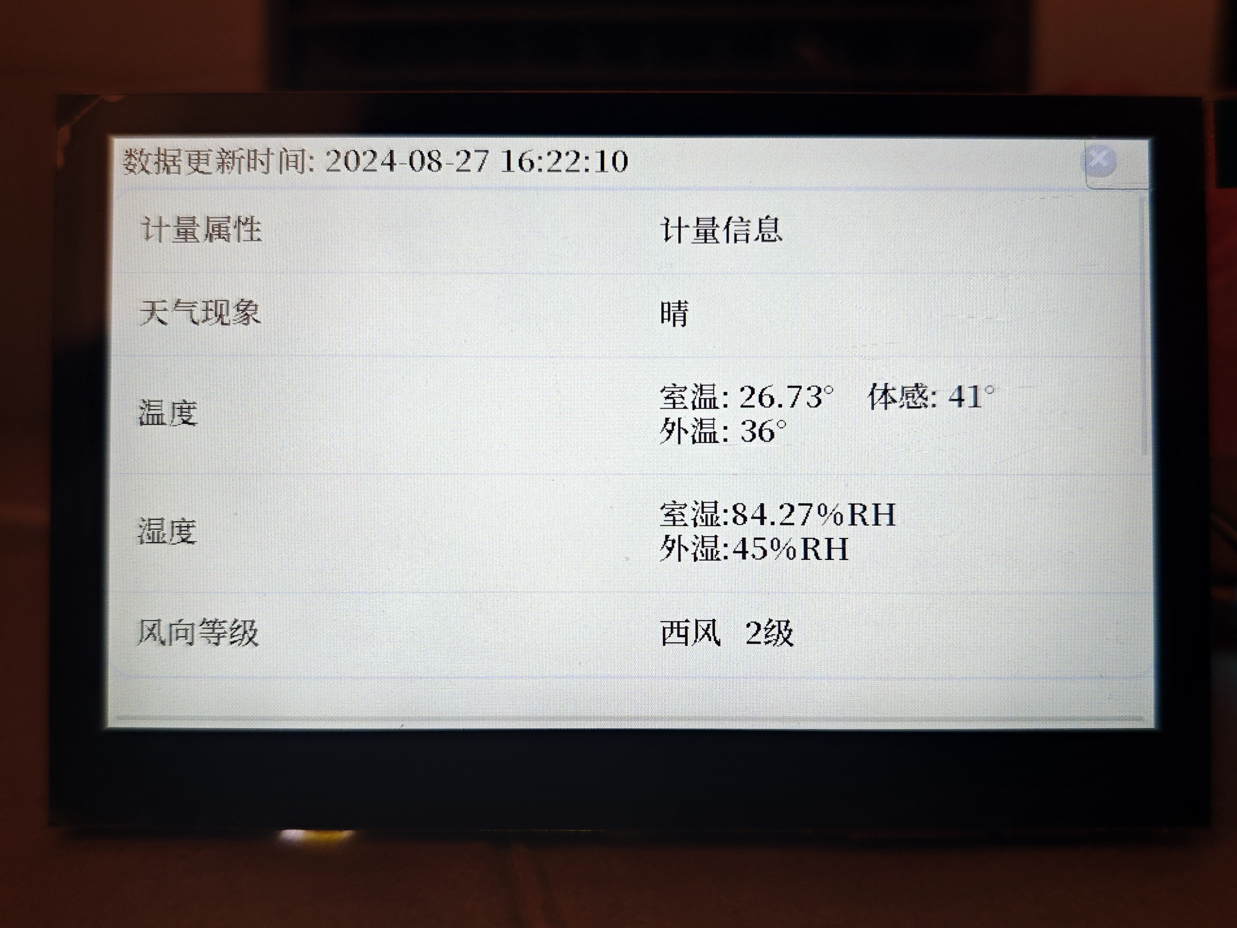
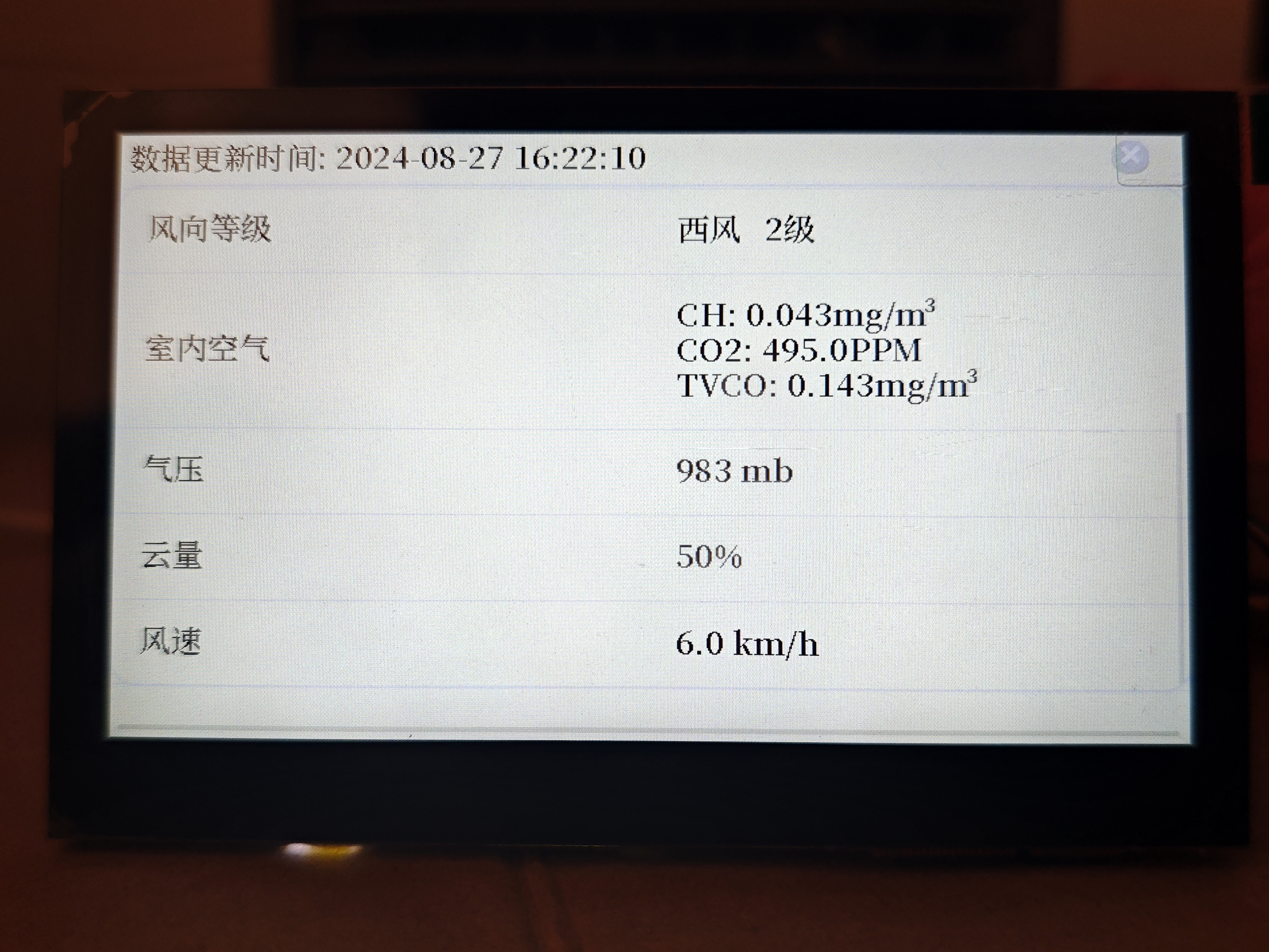
Primarily displays sensor values and weather information from Xinzhi Weather. An exit button is provided.
4.5 Control Interface:
Currently, the control interface mainly focuses on air conditioning control, with an exit button provided. Further optimization and additions will be made later.
5. Due to limited personal capabilities and time constraints, there may be some minor bugs, and some functions are not yet complete. Continued optimization is expected. Link: https://oshwhub.com/dzxhhjn/based-on-liangshan-pai-room-desk
6. Note: The 3D printed shell design is flawed; please do not directly use the 3D files from the project.


 京公网安备 11010802033920号

 54112-811481700LF


