Please apply solder to the opening on the back to increase current carrying capacity, and take short-circuit protection measures (apply sealant) and check. An adapter base housing is included in the accessories; the mounting holes are M3 25X25mm.
The Under One Person manga has been quite popular lately, especially the San Yi Gate arc. I keep seeing people making jade plaques with quotes from the story engraved on them, which I find quite amusing. On a whim, I decided to make one myself using a PCB. Maybe this is the romance of electronics enthusiasts, haha.
This circuit is quite simple; it just powers two ceramic filaments. Then, a filler layer is applied to the top layer, which is the top solder mask layer.
For the image, I used the mobile app "YiTian Camera."
First, take a completely black photo with YiTian Camera. Then, select the editing
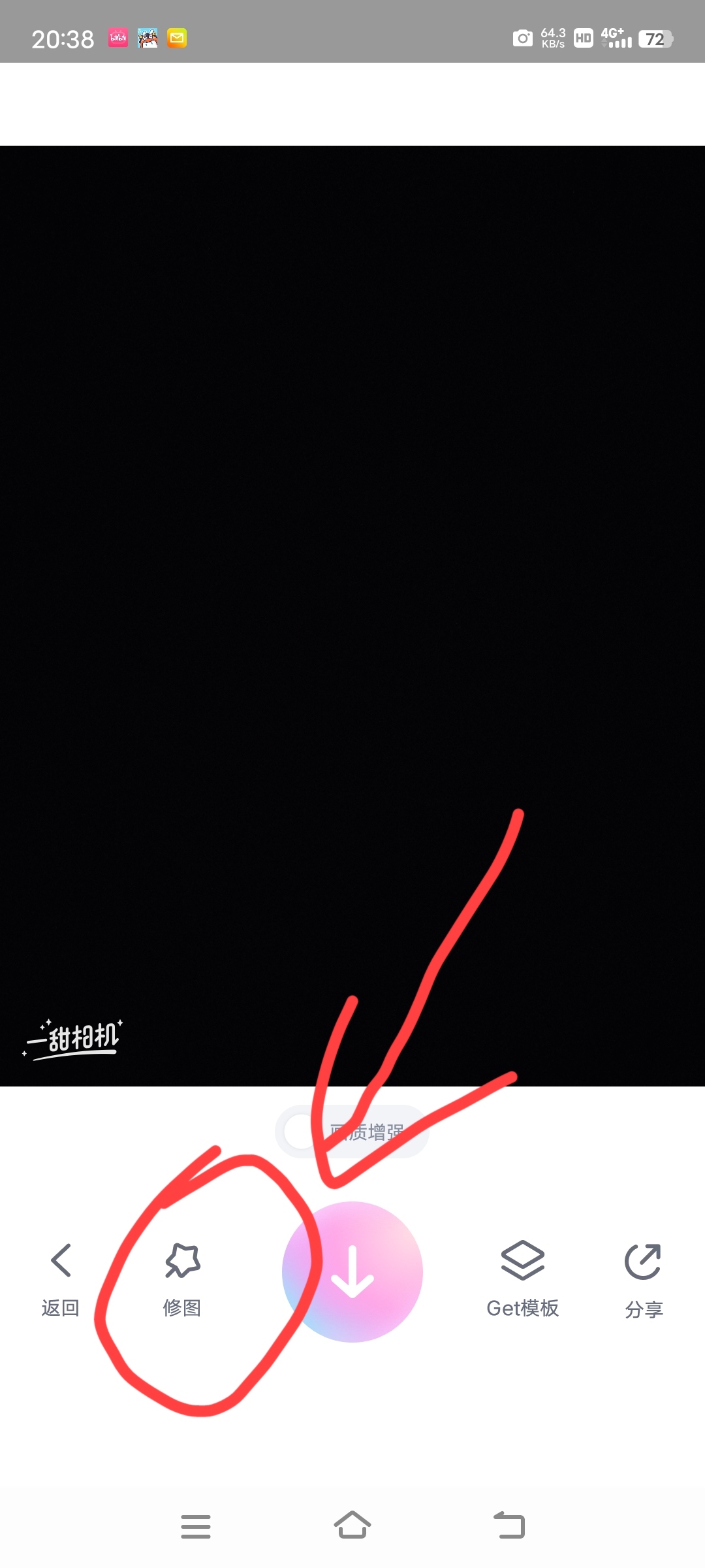
function,

enter the desired text

, and choose the font shown in the image.

Perform some operations such as bolding and adding horizontal strokes, save the resulting image, then take a screenshot of the desired portion with your phone, and import the image into the PCB.
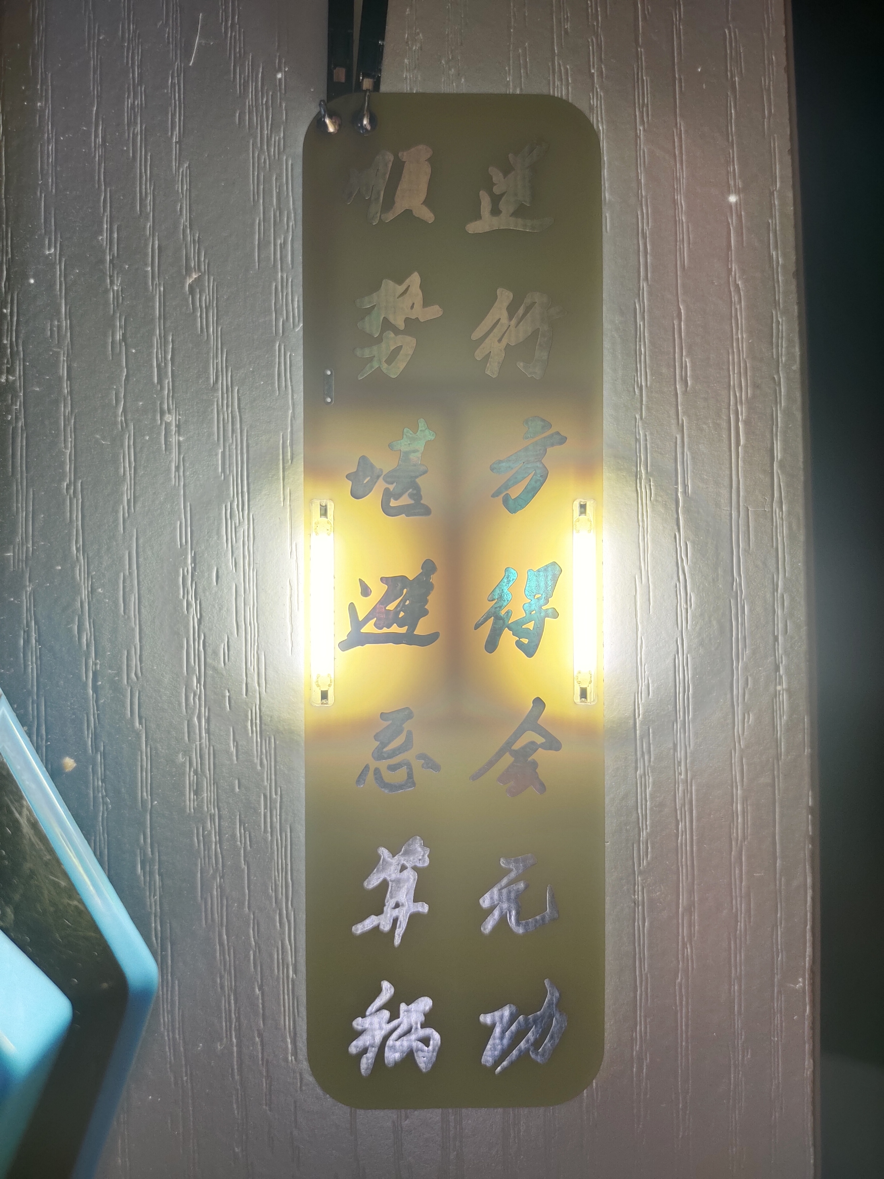
Below is an image of the sign I made:

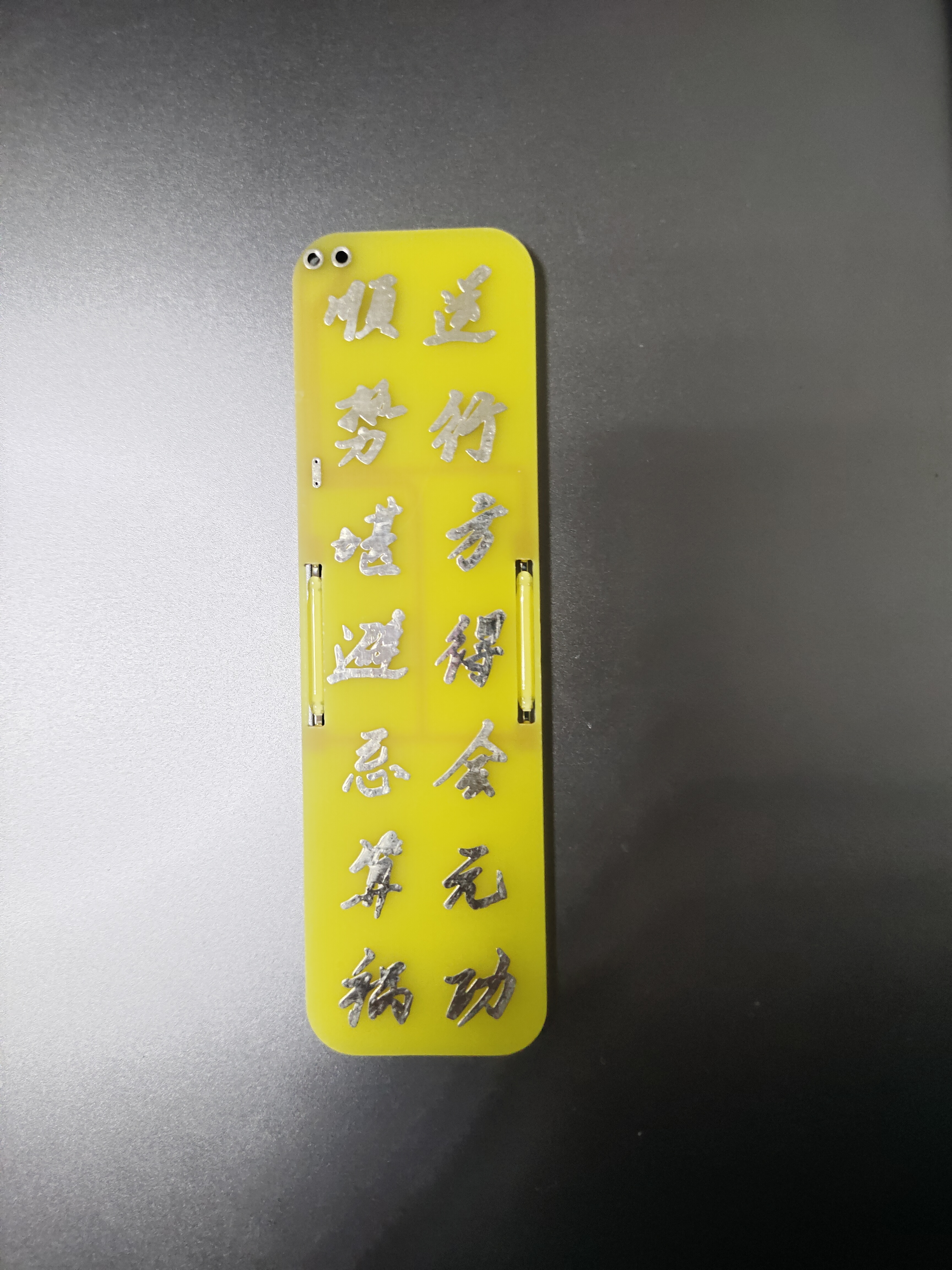

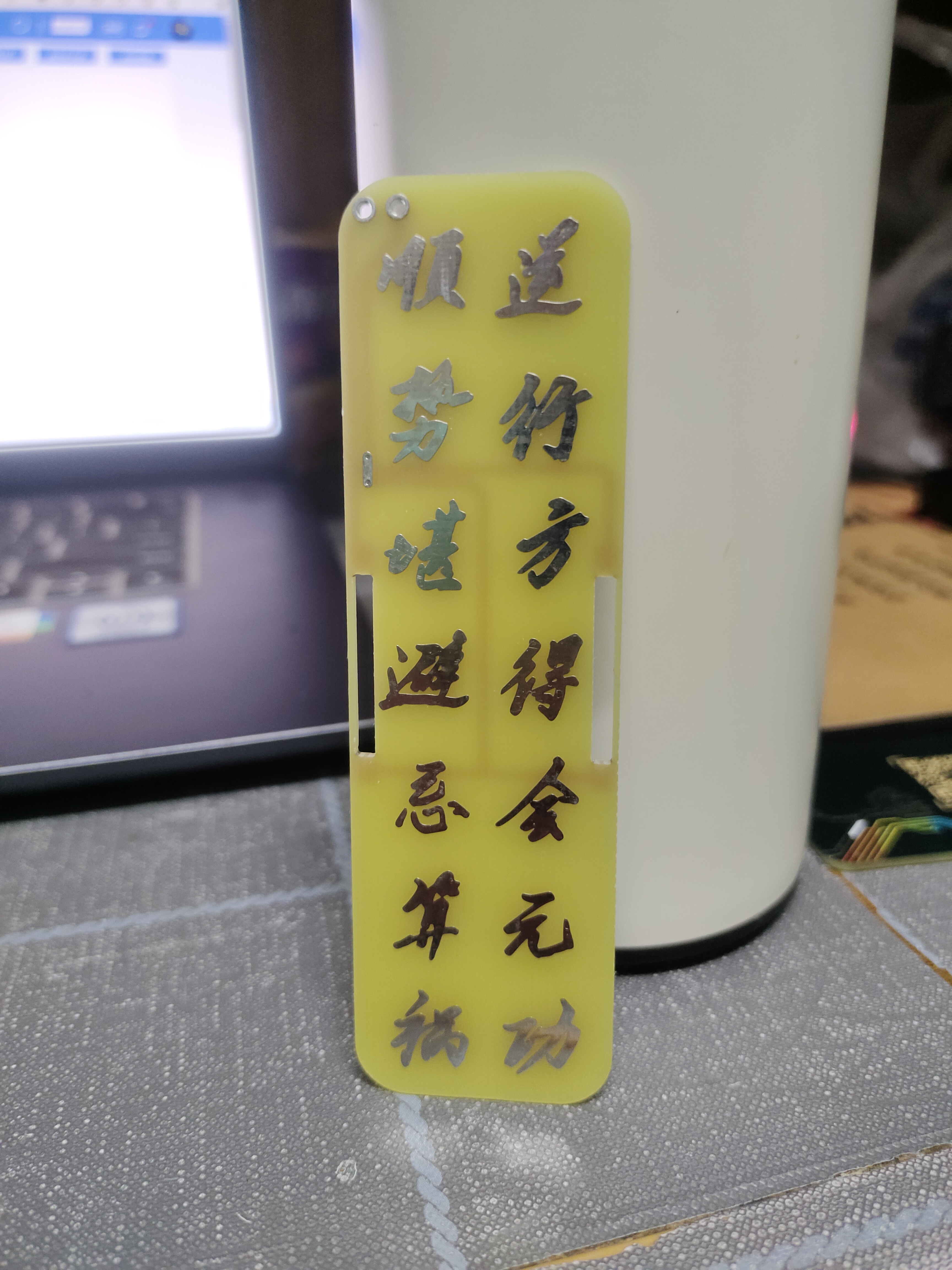
Isn't it nice? It can be used as a bookmark, and it even lights up—and the light is quite bright. If you want to make one, feel free to experiment!
VIDEO1709902430643.mp4
PDF_Under One Person Featured Character Cards.zip
Altium_Under One Person Special Character Cards.zip
PADS_Under One Person Special Character Cards.zip
BOM_Under One Person Featured Character Cards.xlsx
95779
ESP32 C3_MINI_Joystack
ESP32 C3 Remote Control
This is an ESP32 C3 remote control controller, a derivative work based on the work of Bilibili UP: 攀哥define.
1. It can be used for small model airplanes, cars, etc. The program uses Espressif's ESP-NOW protocol; please refer to 攀哥define's case study for the program.
2. The PCB design uses the Heze C3 development board. Considering that remote control doesn't consume too much power (relatively speaking), there is no charging circuit on the controller.
3. Power selection is only achieved through the interference between the switch (SS12D10) and the TYPE-C port (the switch must be in the off position when the USB data cable is plugged in) to ensure power safety.
4. The appearance is inspired by Bilibili UP: saturrn圣骑土; thanks to them for sharing.
PCBA-A-Interference 1.jpg
PCBA-A-Interference 2.jpg
PCBA-B.jpg
PCBA - Video.mp4
PDF_ESP32 C3_MINI_Joystack.zip
Altium_ESP32 C3_MINI_Joystack.zip
PADS_ESP32 C3_MINI_Joystack.zip
BOM_ESP32 C3_MINI_Joystack.xlsx
95780
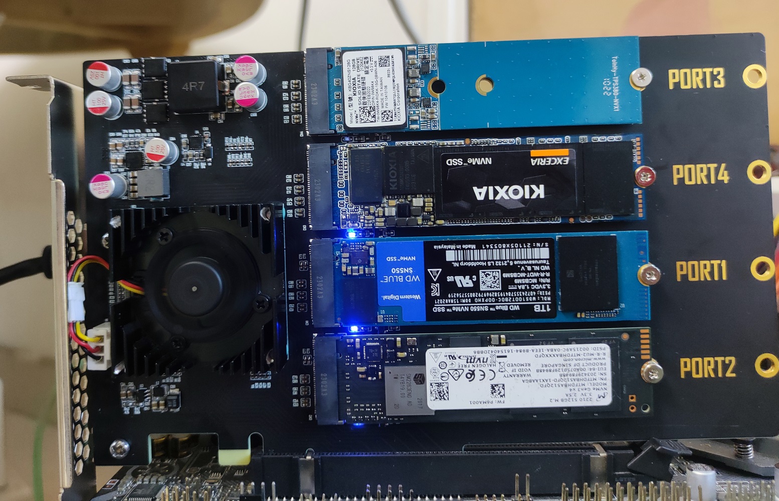
ASM2824 PCIe to M.2 Expansion Card
ASM2824_M.2 expansion card, compatible with ASM2812, ASM1824, and ASM1812.
Using the ASM2824 PCIe switch, four M.2 interfaces can be expanded without requiring the motherboard to support PCIe splitting. It has a built-in clock buffer and supports splitting into up to 12 ports, which can be used to implement multi-port network cards or network card + M.2 expansion cards. Synology's 10 Gigabit + M.2 combo uses this IC. However, chip prices are currently skyrocketing, making your own is not cost-effective.
It is compatible with ASM2824, ASM2812, ASM1824, and ASM1812; ASM18XX only supports PCIe. 2.0, ASMX812's upstream LANE4-7 and downstream LANE8-15 are unusable.
I want to use Huaqiu's 99 RMB 6-layer promotional kit, with 1 oz inner layers and 3u immersion gold, so it's designed according to Huaqiu's 1080 impedance. Using JLCPCB for PCB fabrication requires adjusting the PCIe differential trace width and spacing according to JLCPCB's impedance calculations. 4 layers should be sufficient. The
heatsink holes are 35*35mm, approximately 50mm diagonally. The chip isn't very hot; passive cooling is sufficient.
Installation diagram:
Top view:
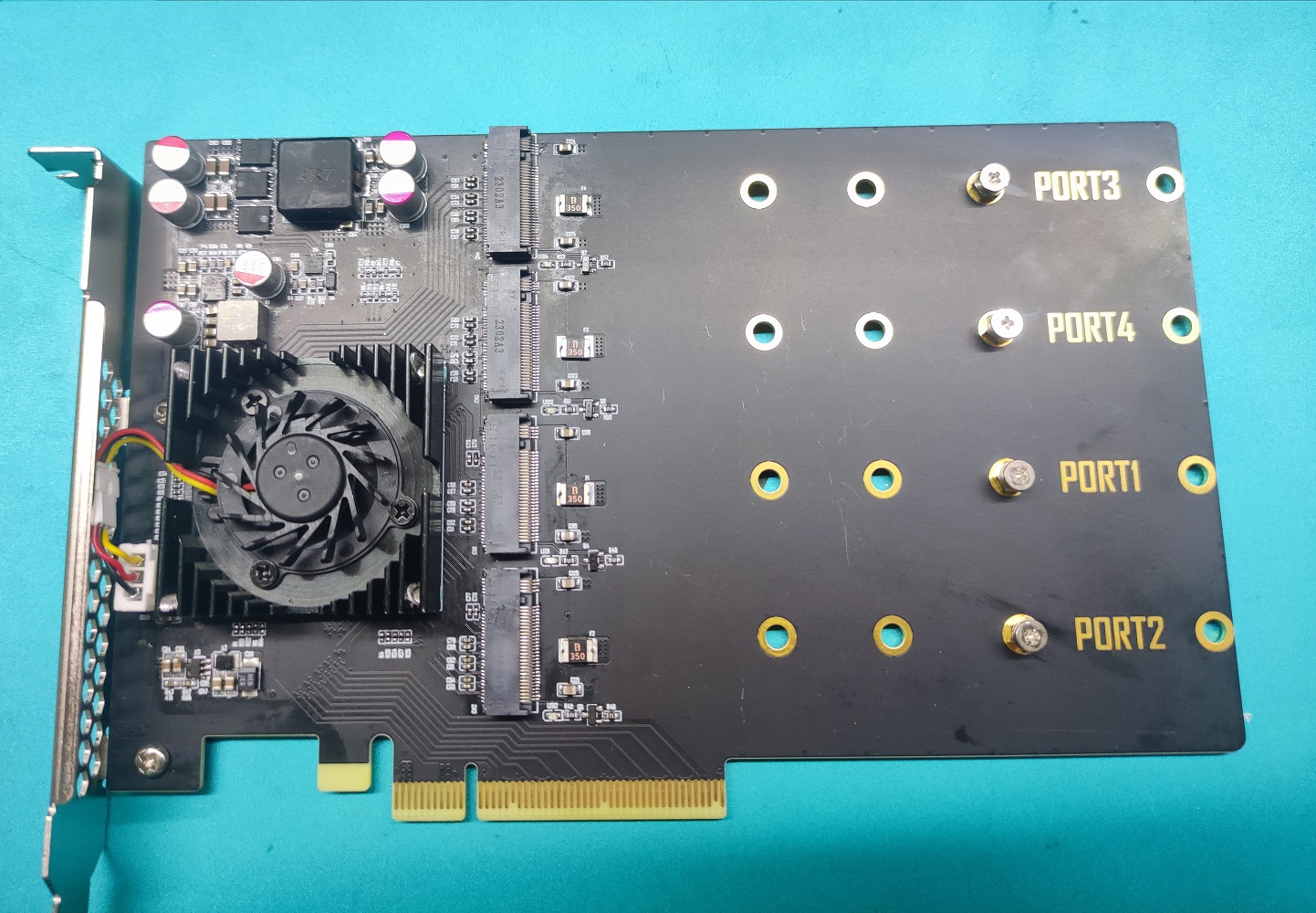
No heatsink Top view:
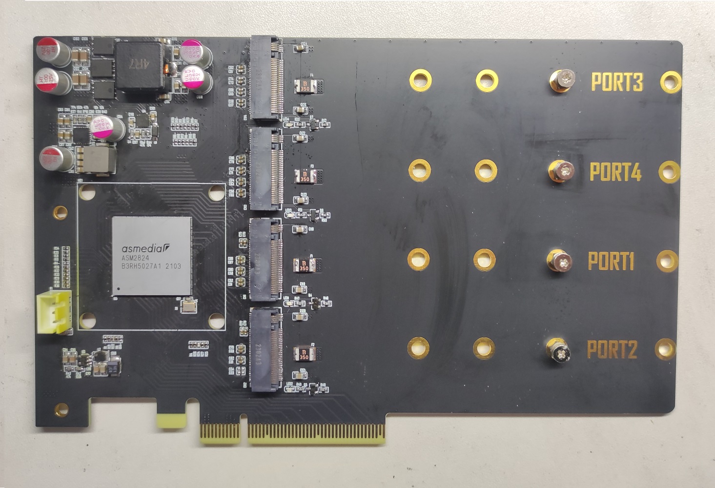
PCB back:

PDF_ASM2824 PCIe to M.2 Expansion Card.zip
Altium_ASM2824 PCIe to M.2 Expansion Card.zip
PADS_ASM2824 PCIe to M.2 Expansion Card.zip
BOM_ASM2824 PCIe to M.2 Expansion Card.xlsx
95782
3D printed rabbit multi-color motherboard
This board was designed with reference to the MMB motherboard and some features from Deepcool motherboards. It has two servo motors, two RGB lighting, one TCR5000 header, and 17 limit switches.
For reference only. I do not recommend custom-designing this board. I'm inexperienced, don't have the time, and have many questions!
I referenced MMB motherboards and added some parts of Deepcool motherboards to design this board. It has two servo motors, two RGB lights, one TCR5000 header, and 17 limit switches,
most of which are copied from MMB motherboards, except for the motors and power supply, which
are still unverified!
PDF_3D Printed Rabbit Multicolor Motherboard.zip
Altium_3D Printed Rabbit Multicolor Motherboard.zip
PADS_3D Printing Rabbit Multicolor Motherboard.zip
BOM_3D Printed Rabbit Multicolor Motherboard.xlsx
95783
Timer Design Based on STC89C52 Microcontroller
The timer design based on the 51 microcontroller is a project developed based on the traditional 8051 series microcontroller. The design will control the start, pause and reset operations of the timer through external buttons, and the timing results can be displayed on the display in real time.
1. Engineering Principle: This timer design based on the 51 microcontroller utilizes the microcontroller's timer/counter module and external interrupt function to achieve timing and counting operations. By programming and configuring the timer, precise time measurement can be achieved, and the start, pause, and reset operations of the timer can be controlled via external buttons.
2. Function: The main function of this design is to provide a reliable timer function for measuring time, implementing timing operations, and displaying the timing results on a monitor. Users can control the timer via external buttons or other input devices, thus achieving flexible timing functionality.
3. Operating Conditions:
Stable power supply voltage, meeting the operating requirements of the 51 microcontroller.
A properly connected monitor capable of displaying timing results.
4. Test Parameters:
Test the accuracy and stability of the timer. Test the normal operation of the external interrupt function. Test the reliability of the button control function. Test whether the monitor can correctly display the timing results. Test the real-time performance and reliability of the entire system.
PDF_Timer Design Based on STC89C52 Microcontroller.zip
Altium-based timer design using STC89C52 microcontroller.zip
PADS_Timer Design Based on STC89C52 Microcontroller.zip
BOM_Timer Design Based on STC89C52 Microcontroller.xlsx
95784
MP1593DN step-down module
The MP1593 is a monolithic buck switching regulator with integrated internal power MOSFETs. It achieves 3A of continuous output current over a wide input range, offering excellent load and line regulation. Its current control mode provides fast transient response and makes the loop easier to stabilize.
Output current: 3A
adjustable; soft-start function
; 100mΩ internal power MOSFET switch
with low ESR; output ceramic capacitor ensures stable operation with
efficiency up to 95%
; 20μA shutdown mode;
385kHz fixed frequency
over-temperature shutdown protection; cycle-by
-cycle overcurrent protection;
wide operating input voltage range: 4.75V to 28V
; adjustable output voltage from 1.22V
; undervoltage lockout (UVLO) protection;
uses an 8-pin SOIC package;
tested without issues with 24V, 3A input load; heat sink required for long-term full-load operation.

MP1593 Datasheet.pdf
PDF_MP1593DN step-down module.zip
Altium_MP1593DN step-down module.zip
PADS_MP1593DN step-down module.zip
BOM_MP1593DN step-down module.xlsx
95785
DRV8313 low-power FOC driver board
Low-power FOC driver board based on DRV8313
For those interested in learning FOC, you can check out the repository at https://gitee.com/HappyAncia. It contains FOC code I wrote based on this driver board and a found STM32F103C8T6 minimum system board. Feel free to learn together!
Closed-loop position FOC.mp4
Closed-loop current FOC.mp4
PDF_DRV8313 Low-Power FOC Driver Board.zip
Altium_DRV8313 low-power FOC driver board.zip
PADS_DRV8313 low-power FOC driver board.zip
BOM_DRV8313 Low Power FOC Driver Board.xlsx
95786
Electronic Butterfly
Based on the principle of free access, an improved "breathing" electronic butterfly has been created, capable of blinking without any code. Original author: [Xiao Jun Chou], LCSC Open Source Platform.
I.
The overall schematic diagram of the LED blinking device is as follows:
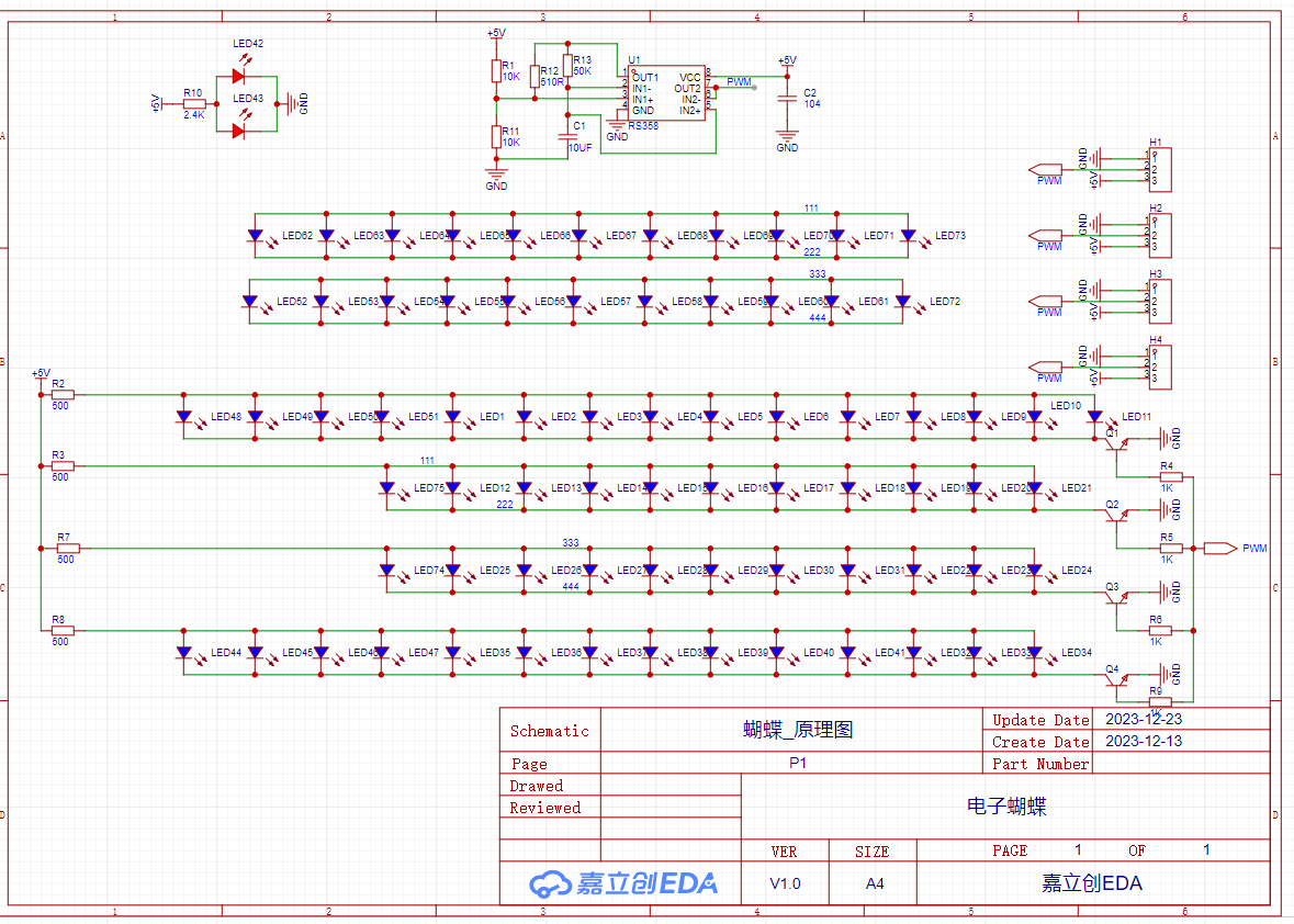
Working principle: The operational amplifier U1 continuously charges and discharges capacitor C1, resulting in a triangular wave (red waveform) as shown in the diagram. This triangular wave is then used to control the switching on and off of the transistor, thus achieving LED blinking.
The blinking speed is determined by the capacitor's charging and discharging cycle, which is three times the time constant (it is generally believed that the capacitor is fully charged or discharged after three times the time constant).
Therefore, adjusting the LED blinking speed only requires changing the values of R13 and C1. Try it out yourself!
PS: The PWM logo on U1 is just a random name I made up; the actual waveform is also a triangular wave, but I added a voltage follower stage to increase the load-driving capability of the triangular wave. For

PCB soldering, refer to the original author's instructions; I'm too lazy to write it out. II. The schematic diagram of
the PCB support bracket is as follows: Working principle: H1 is a 5V external power socket (why leave a socket? Because freebies make me happy); an additional Type-C interface is reserved, but only the 5V power supply pin is connected. Either power interface can be selected, or both can be plugged in simultaneously. There is a diode for reverse polarity protection, so don't worry. PCB Soldering Instructions: III. Material Preparation: 1. All electronic components, sourced from [company name] for free; 2. PCB, sourced from JLCPCB for free; 3. Soldering tools, sourced from [company name] for free; although I also have some in stock, getting things for free makes me happy (doge emoji for protection). IV. See attached project files for physical demonstration . Video on Bilibili: https://www.bilibili.com/video/BV1he41127hb/?vd_source=bc354c22d786c4e0b934a0e443fd6509


Breathing Electronic Butterfly [Project File].epro
PDF_Electronic Butterfly.zip
Altium_ElectronicButterfly.zip
PADS_Electronic Butterfly.zip
BOM_Electronic Butterfly.xlsx
95787
Intelligent LED Strip System - Aurora
The ESP32-based smart light strip system, based on Blinker, supports: Xiao Ai voice assistant, flowing light effects, weather and time display, sedentary reminder, and computer shutdown.
This smart light strip system, based on ESP32 and Blinker, supports: Xiao Ai voice assistant, flowing light effects, weather and time display, sedentary reminder, and computer
shutdown. The project is open-source at https://github.com/bszydxh/smart_light_system
and includes an Android and PC client.
This board is only a data board and cannot be used to directly drive the light strip.
Video 1 demonstrates the flowing light effects;
Video 2 demonstrates computer-controlled light strip operation.
208168212-7c93ab88-0b14-446b-8acc-c92a9ee06c3b.mp4
208168375-cefdf474-2f2c-4264-8bb8-2c2823d160cd.mp4
PDF_Intelligent LED Strip System - aurora.zip
Altium Smart LED Strip System - aurora.zip
PADS Smart LED Strip System - aurora.zip
BOM_Intelligent LED Strip System-aurora.xlsx
95788
electronic


 京公网安备 11010802033920号

 854L8B-1


