Bilibili video demonstration: https://www.bilibili.com/video/BV135pUeMEFw
Documentation tutorial: https://wiki.lckfb.com/zh-hans/dwx-cw32f030c8t6/training/voltammeter-bootcamp/voltammeter.html
Bilibili video tutorial: https://www.bilibili.com/video/BV19r421M7Fp
If you want to replicate it, it is recommended to replicate this project: https://oshwhub.com/rushairer/cw32-voltage-ammeter-training-ca
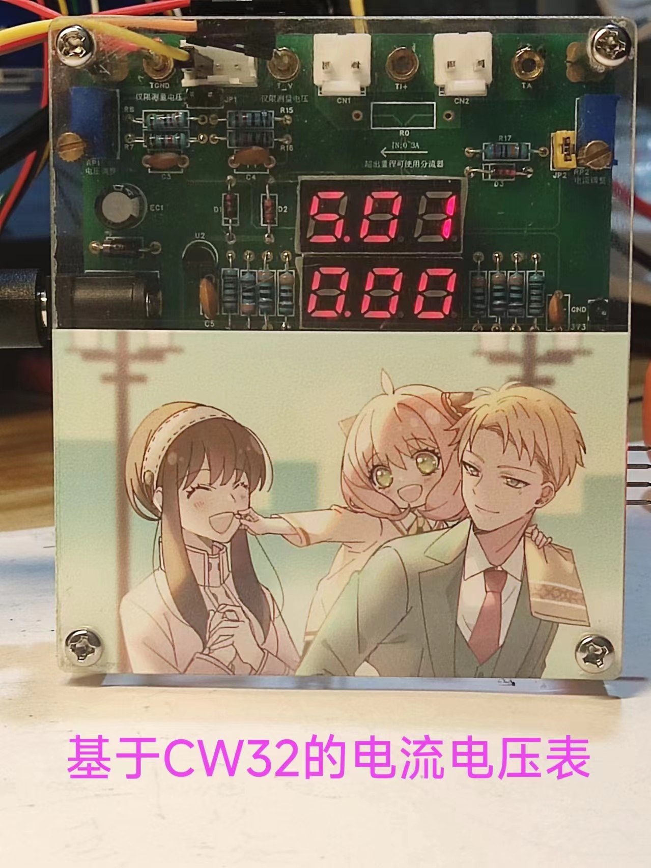
Its interface uses three 4mm horizontal connectors: one for voltage, one for current, and one for ground. It also features a 3D casing, making it both aesthetically pleasing and practical.
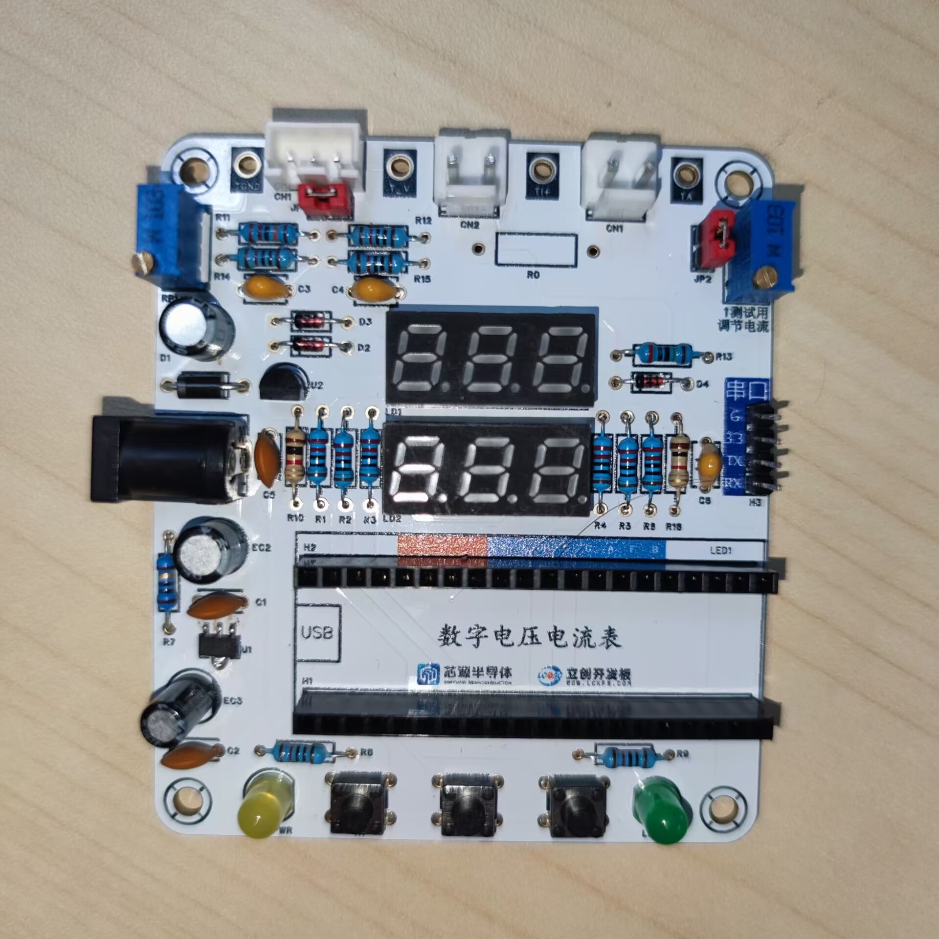
Actual product photos:
Experiments 1-9 Project.zip
PDF_CW32 Voltage and Current Meter.zip
Altium_CW32 voltage and current meter.zip
PADS_CW32 Voltage and Current Meter.zip
BOM_CW32 Voltage and Current Meter.xlsx
93032
CW32 Voltage and Current Meter
A voltage and current meter made using a CW32 microcontroller
This is my first time running a training camp. I followed the tutorial step by step, and here's a sharing
of the results!

The main controller used is the CW32F030C8T6. The CW32's ADC is excellent and very suitable for the needs of this project.
Power supply circuit:
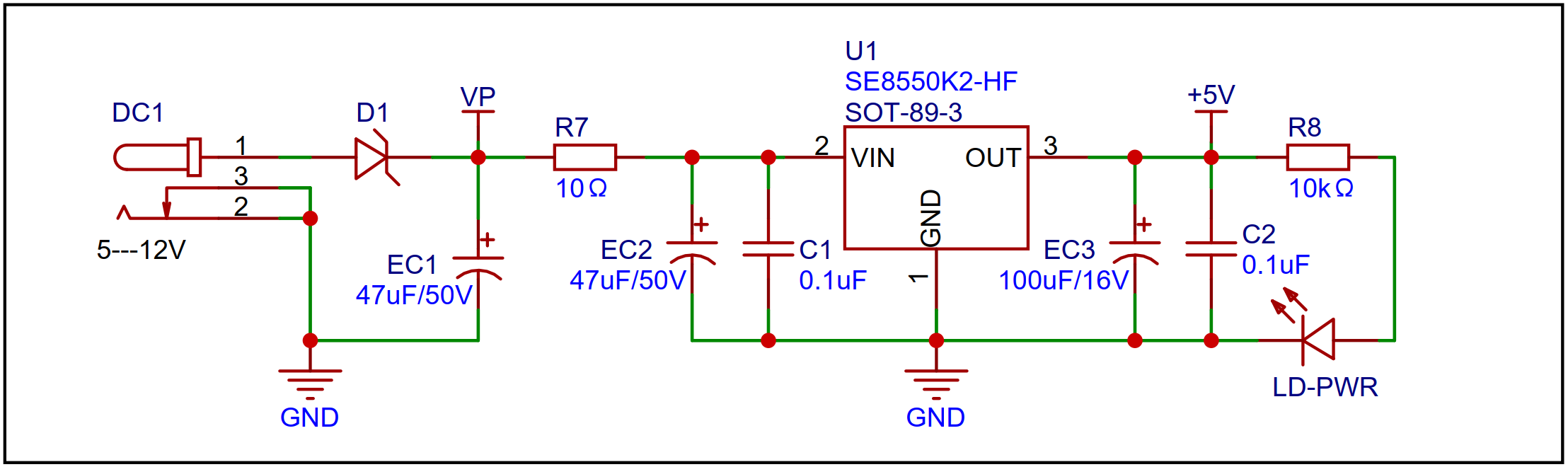
An LDO is used as the power supply, with an SE8550K2 chip selected. It can handle up to 40V input voltage, meeting 24V and 36V DC power supply scenarios.
A Schottky diode was used for reverse connection protection. Diodes have a certain voltage drop, and using a Schottky diode results in a smaller voltage drop. Using a diode for reverse connection protection also considered cost.
A small resistor (R7) is connected in series, which can be used for voltage division, reducing LDO heat generation when the input voltage is high, and also acts as a fuse.
Voltage sampling circuit:
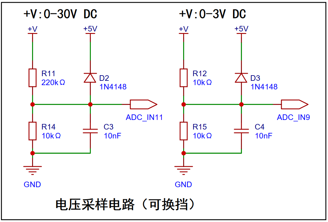
The voltage sampling circuit uses two sampling channels, with different resistors for voltage division, to achieve two measurement levels. With the ADC reference set to 1.5V, the sampling resistor ratio for 0~30V should be 20:1. To reduce power consumption, R14 is chosen as 10K, and a resistor slightly larger than 200K, R11, is chosen as 220K. Of course, the sampling resistor ratio can be changed to expand the measurement range.
The current sampling circuit
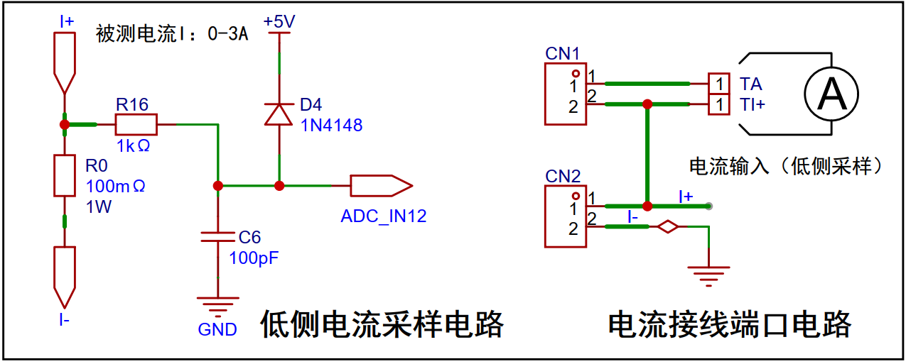
uses a 100mΩ sampling resistor. The principle is that current passing through the resistor generates a voltage drop, and the current magnitude is obtained by sampling the voltage across R0. The accuracy of R0 should be as high as possible, and the resistor's heat generation should be considered; here, a power rating of 1W is chosen.
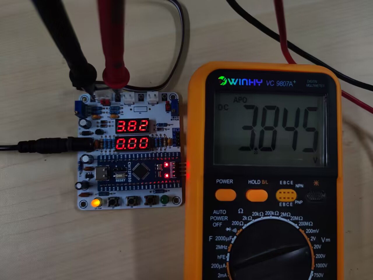
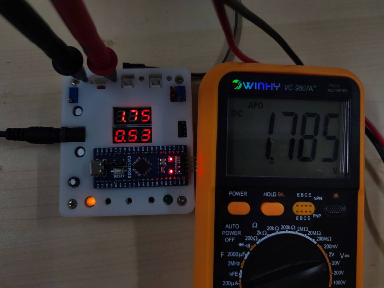
Physical demonstration:
This is a 3D-printed shell
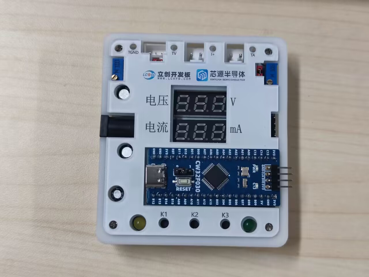
placed on the panel. My buttons are relatively short, so they are not pressable with the shell on.
Function demonstration:
Pressing the K1 key enters calibration mode. The upper digital tube displays the value to be calibrated, and the lower digital tube displays the currently measured voltage or current. Pressing the K2 key updates and saves the calibration, and the K3 key returns to measurement mode.
Software part:
The code is uploaded as an attachment. For the digital tube display part, the code directly manipulates the registers, which is more efficient.
Software Engineering.rar
Schematic diagram of voltage and current meter.pdf
Demo video.mp4
PDF_CW32 Voltage and Current Meter.zip
Altium_CW32 voltage and current meter.zip
PADS_CW32 Voltage and Current Meter.zip
BOM_CW32 Voltage and Current Meter.xlsx
93034
Cabinet motion sensor lights
A simple wardrobe light with 4 LEDs, a 1200mAh lithium battery, integrated lithium battery charging management circuit, one-button high-brightness lighting, reed switch magnetic control circuit, and a 3D printed unibody casing.
This is a simple wardrobe light with four LEDs, a 1200mAh lithium battery, a lithium battery charging management circuit, a charging indicator light, and a 3D-printed unibody casing. It features
one-button high-brightness lighting; pressing and holding the button activates two of the LEDs.
A reed switch magnetic control circuit, in conjunction with a magnet, enables automatic light activation when the cabinet door is opened.
The circuit is highly streamlined, requiring only seven resistors and two capacitors.
A mounting bracket is included for easy removal and charging later.
This design is an improvement upon the cabinet door sensor light project from the LCSC open-source hardware platform (oshwhub.com), removing many unnecessary components to reduce replication costs and make it easier to replicate. Thanks to the original author, the open-source
circuit board has been verified and can be directly prototyped.

Component Links.xlsx
Top cover 1.stl
Bottom cover 1.stl
support.stl
PDF_Cabinet Sensor Lighting.zip
Altium_Cabinet Sensor Lighting.zip
PADS_Cabinet Sensor Lighting.zip
BOM_Cabinet Sensor Lighting.xlsx
93035
Lithium battery charge and discharge management board
Measurement and management of charging (TP4056) and discharging (op-amp negative feedback constant current) of small-capacity 1S lithium batteries.
The circuit section
uses a Type-C port to provide 5V power, employs an ATmega168/328 as the main controller, amplifies the current through an operational amplifier, and uses an on-chip ADC with a TL431 reference voltage source to collect the battery's current and voltage, enabling the monitoring of charging and discharging current and voltage. I/O ports control the enable and current-limiting resistors of a TP4056 to achieve adjustable charging current (30mA steps) for the lithium battery. A PWM output after RC filtering acts as a DAC, which is input to the operational amplifier feedback terminal to control a MOSFET as a constant current source for adjustable current discharging. The main controller controls a 0.91-inch OLED screen and buttons to display and adjust the above functions.
The software section
is a simple program based on Arduino + PlatformIO, quite rudimentary, with the main functions being:
1. Set charging current and prompt when fully charged.
2. Set discharge current and termination voltage and prompt when fully discharged
. 3. Set discharge capacity and prompt when fully discharged.
4. Close the charging and discharging circuit and monitor the real-time voltage and current between the lithium battery and the output terminal.
5. Settings, including
(1) Buzzer enable
(2) Thermistor temperature limit discharge current
(3) Constant current discharge end stage current correction.
The physical display
picture shows the old version PCB, which has a small bug. The new version has fixed it (not tested on the board, but passed the flying wire test). The current measurement principle has been updated (measure voltage -> measure voltage difference), and it has been corrected in the PCB and program (open Current Fix in settings).
Supplement:
This is just for fun. I am not very good at digital and analog electronics. There may be problems in the circuit and software (quite a few). Welcome to criticize and correct. I do not have professional instruments on hand. I used a multimeter to test the current deviation, which was about 0.05A. The charging and discharging function is normal. The statistical data graph is just for fun. When discharging without additional heat dissipation, it is about 0.5A/80℃. I dare not test it higher. The project involves high temperature and lithium battery. Please assess the safety yourself.
BatteryManager.zip
PDF_Lithium Battery Charge and Discharge Management Board.zip
Altium lithium battery charge/discharge management board.zip
PADS_Lithium Battery Charge and Discharge Management Board.zip
BOM_Lithium Battery Charge and Discharge Management Board.xlsx
93036
[PD Charging] Mini Ductless Grip Controller
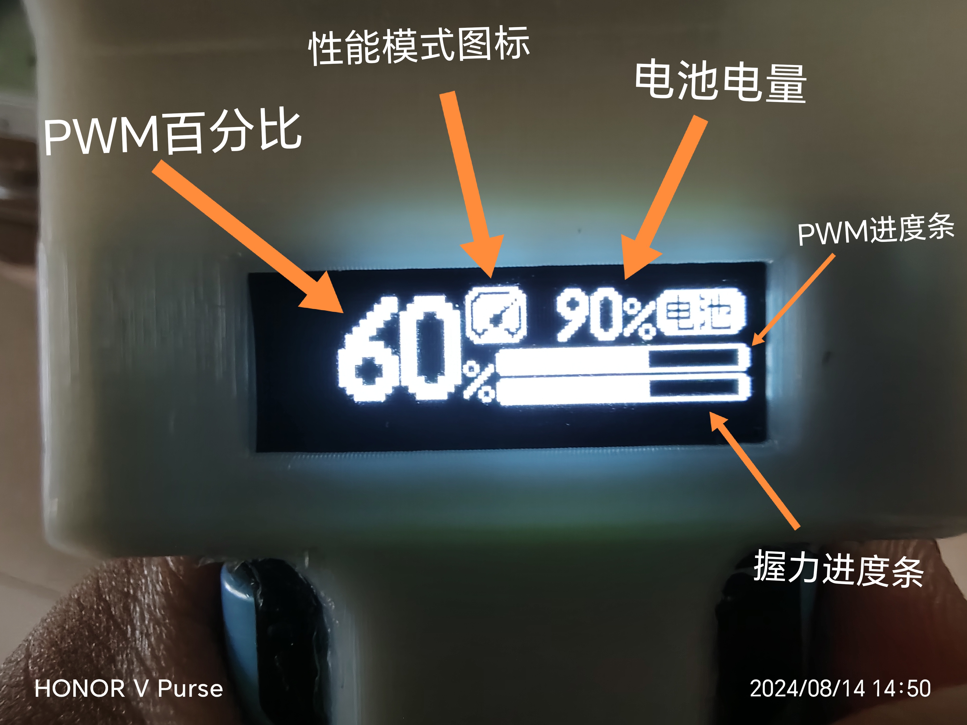
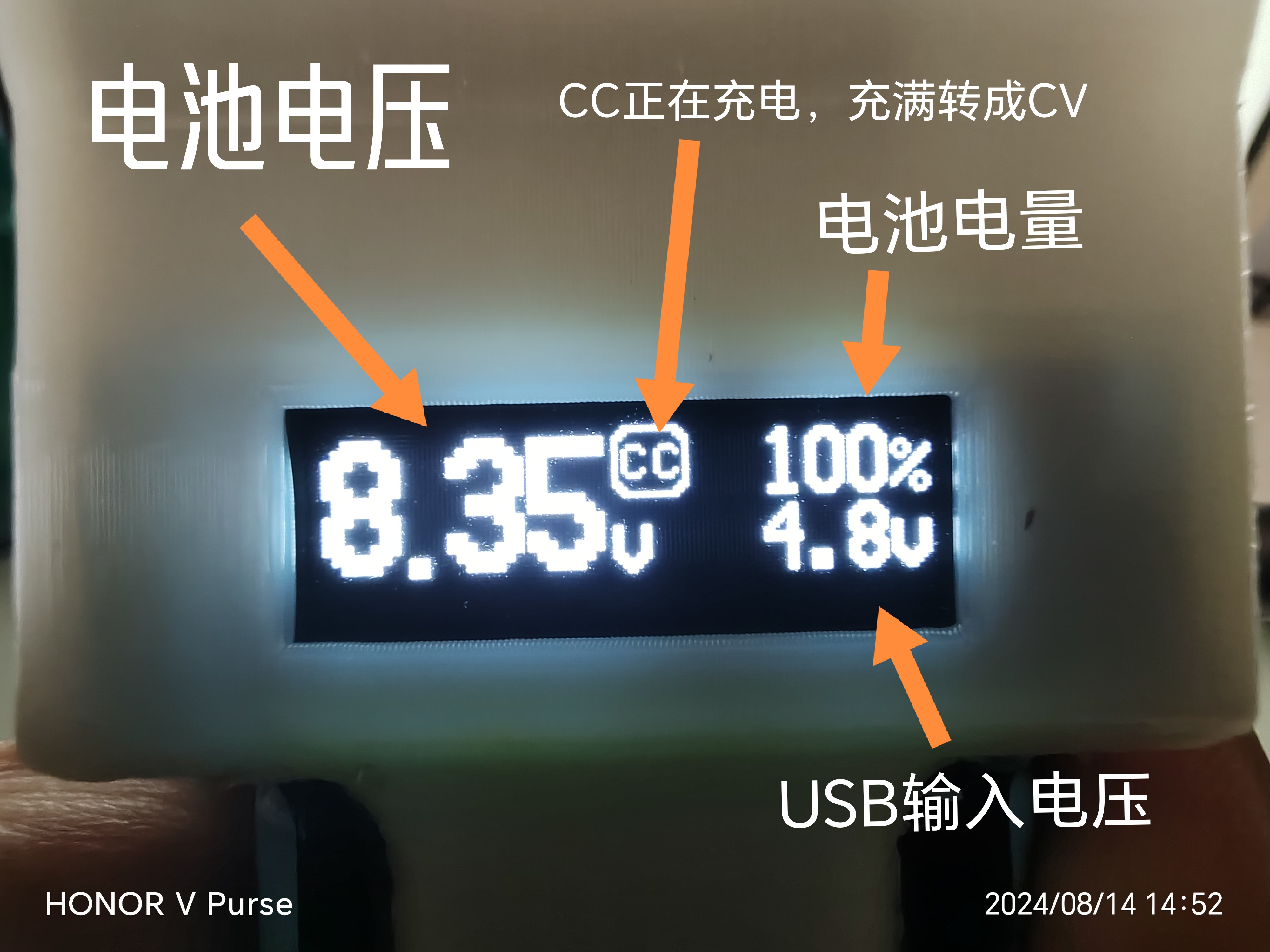
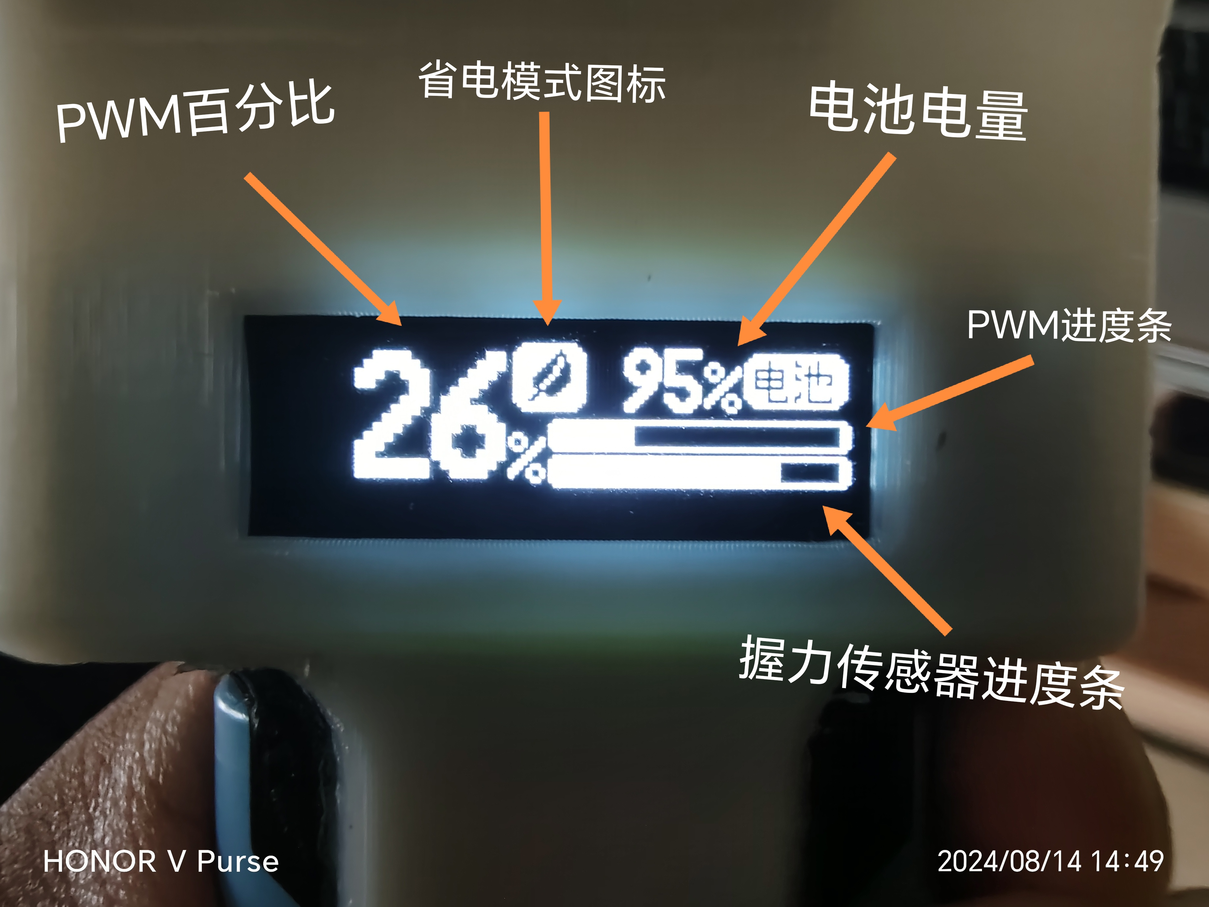
This project developed a PWM signal generator suitable for brushless ESC speed control. It features a compact size, high integration, and other advantages. Functions include one-button power on/off, PD 15W boost fast charging, grip strength control, PWM parameter adjustment, low battery protection, battery balancing, and an OLED display UI.
(1) This project includes:
1. lcEDA pcb project
2. BOM
3. Keil5 C language project
4. HEX file
5. SolidWorks component project
6. STL file
7. In-program display bitmap file
(2) Required components (modules): 1.
29mm 7.4V low-voltage ducted fan
2. Little Bee 30A BlHeli-s 2-6s ESC
3. Circular 5mm long-tail flexible resistive thin-film pressure sensor
4. 0.91-inch OLED display module IIC 12832
5. 18650 battery box with pins on the back
6. Two 18650 power batteries (discharge above 10A)
7. C8051F emulator, etc. (requires a downloader that supports C2 interface)
8. USB to TTL serial port downloader
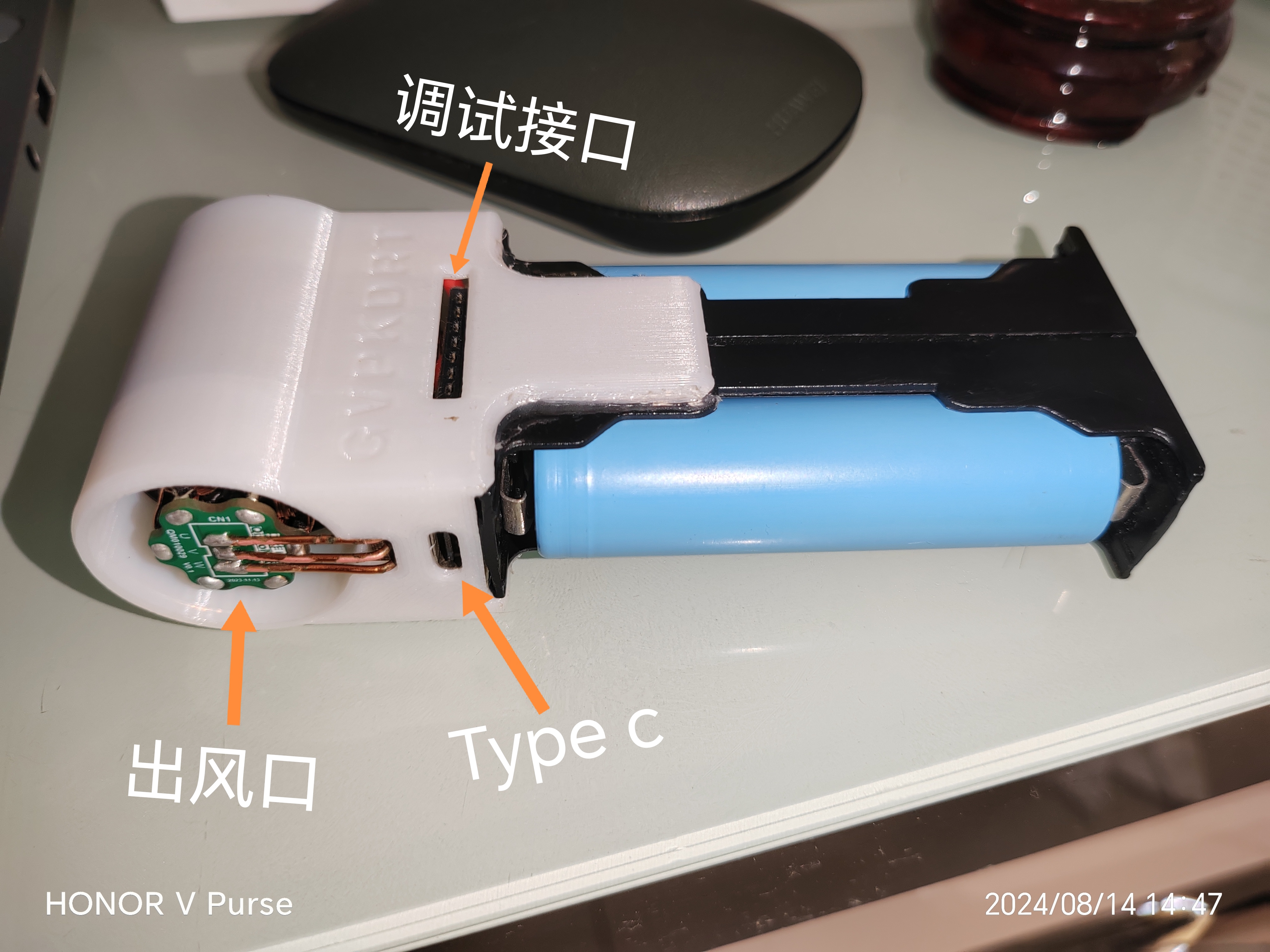
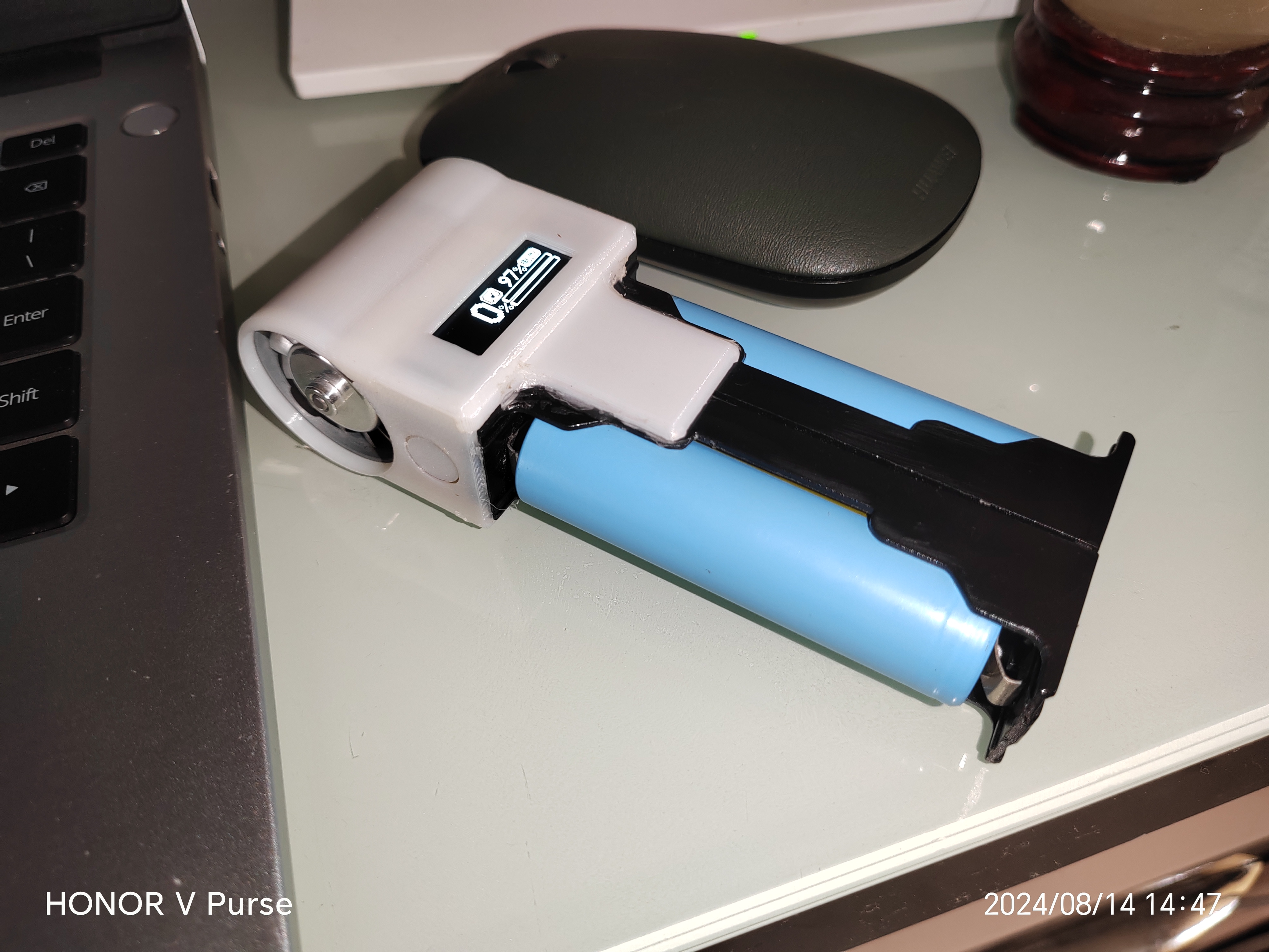
(3) Physical introduction:
![Screenshot_20240814_151545_com.hihonor.photos.png]

![IMG_20240814_145954.jpg]
![IMG_20240814_145715.jpg]
![IMG_20240814_144930_edit_1594232154315231.jpg]
![IMG_20240814_144752_edit_1594618452232584.jpg]

![IMG_20240814_144757_edit_1594559449913700.jpg]
![IMG_20240814_144743.jpg]
(4) Illustrated tutorial:
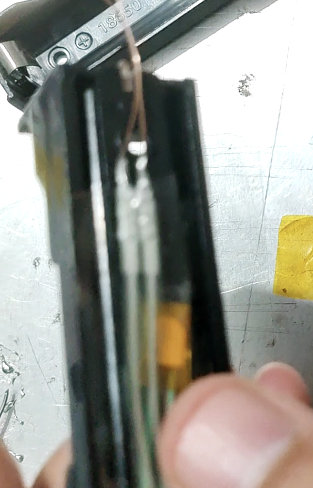
First, process the ESC. Peel off the heat shrink film of the ESC and remove all connecting wires: Next
,

remove the LDO chip, disconnect its 3.3V output from the circuit board, ensure proper insulation, and reinstall it. Use six enameled wires to connect the LDO's 3.3V output, the ESC's S-terminal (PWM input), and the four test points. Make sure you remember which wires are connected correctly. Before reinstalling the power cord
,
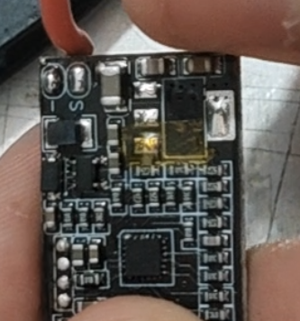
bend the tinned portion of the wire at a 90° angle to shorten the ESC's length.
[Image 1]

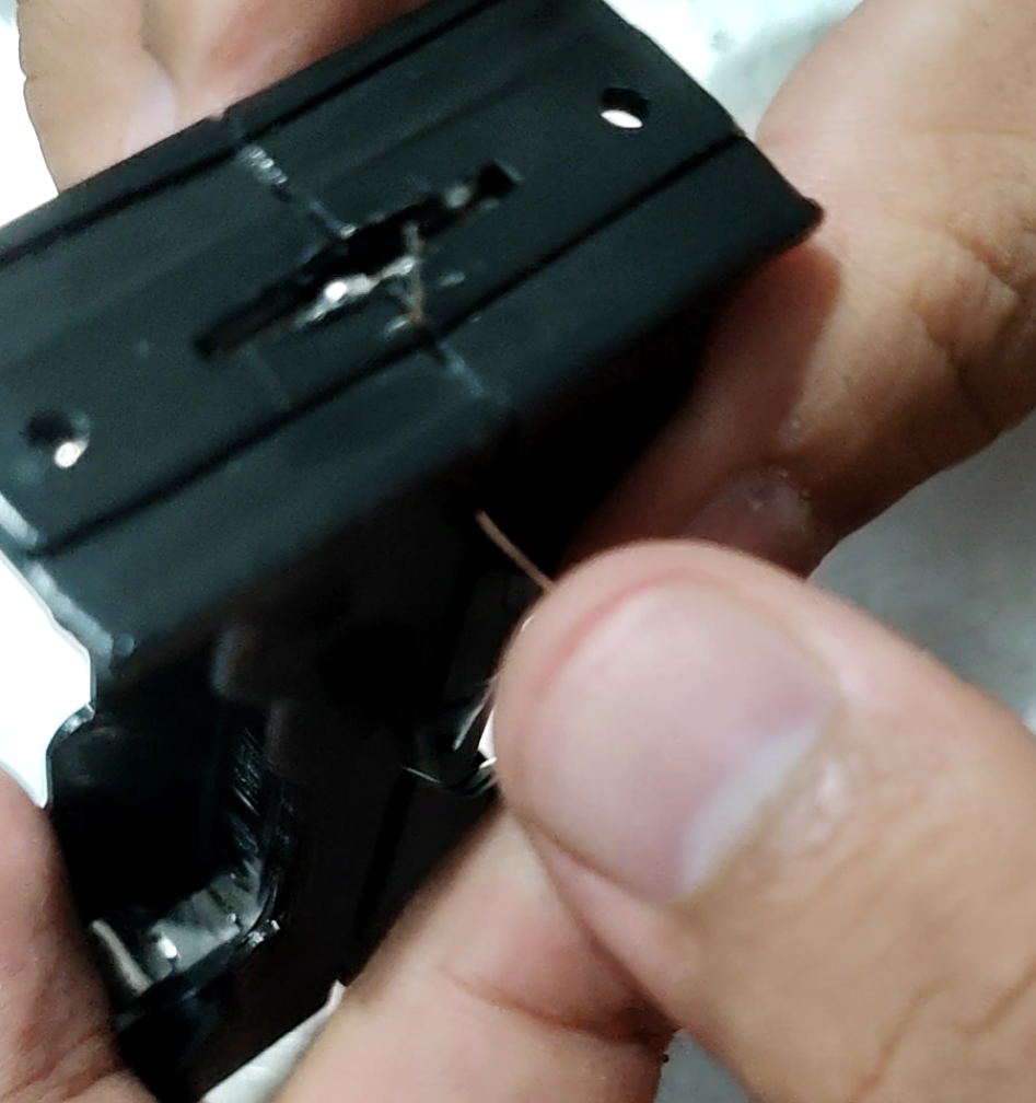
The test point definition is shown in the figure.
[Image 2]

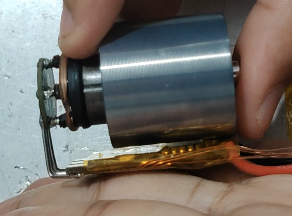
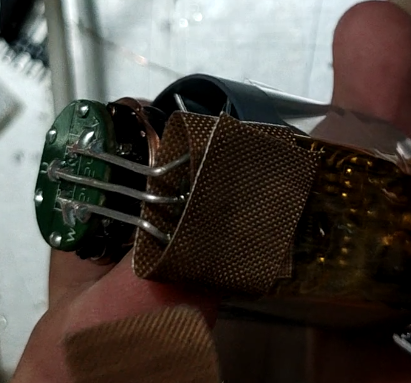
Wrap the ESC with high-temperature tape and connect it to the motor as shown in the figure. Note that the ESC MOSFET face should face the motor, and the power supply terminal of the ESC should be aligned with the motor's air inlet casing.
[Image 3

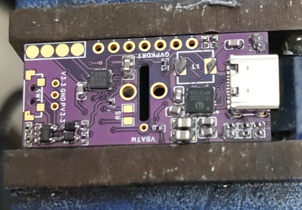
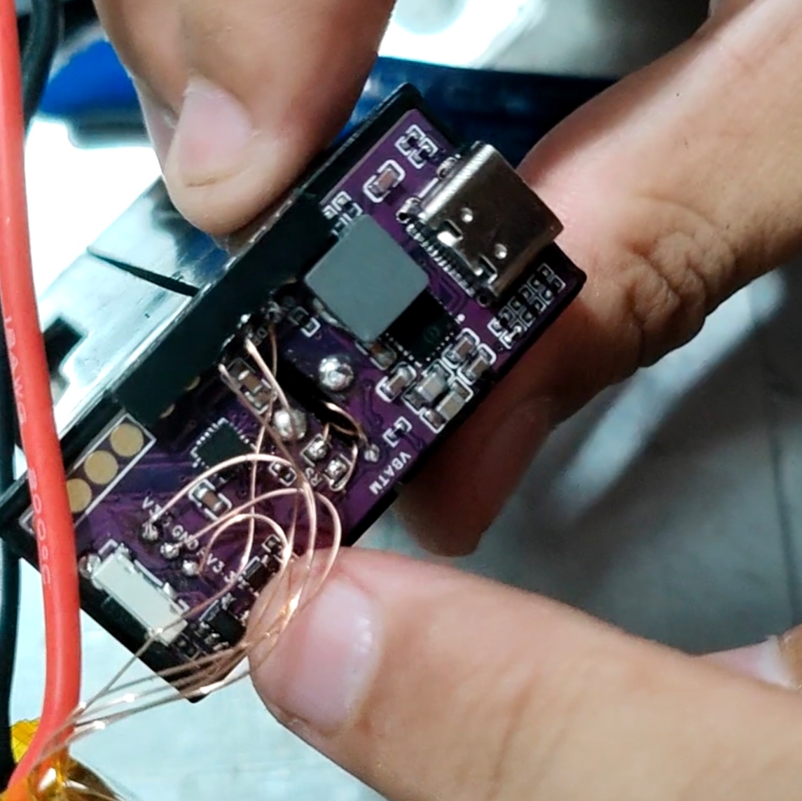
] Apply solder paste as shown in the
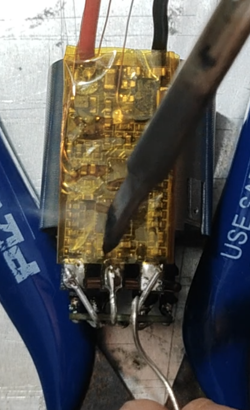
figure
and mount the components according to the BOM. Note the orientation of the chips and diodes, and ensure that the chips are properly soldered before mounting the inductor. The buttons should be soldered with medium-temperature solder (low-temperature soldering is not strong), and the Type-C connector should also have its housing pins reinforced with medium-temperature solder. [
Images 1]
[Images 2]
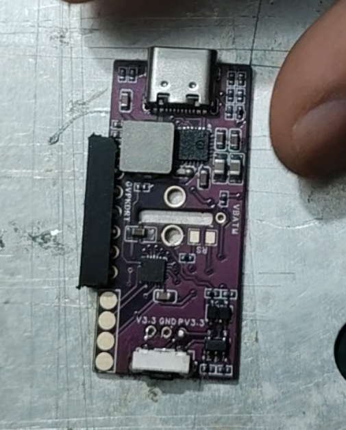
After checking and confirming everything is in order, use a short-pin connector, bend the pins, and solder it to the debugging interface.
[Images 3]
Now you can download the program. Use the STC-ISP software:
Set the chip model: STC8H1K08.
Set the serial port (select USB to serial module).
Open the program file: the hex file for this project.
Set the frequency to 30MHz.
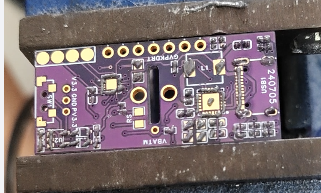
Connect the RX and TX pins of the debugging interface: (There is a string of letters next to the debugging interface, GVPKDRT, which stands for GNDV3.3PWMCKCDRXTX).
Click Download/Programming, and then power on the circuit board according to the prompts.
(Once the program is written, you can connect the screen to test it. The four pads next to the debug port are the screen interface. The first pad on the button is GND, and the next three should be soldered in the same order as the screen port. After soldering, connect the V3.3 and GND of the debug port, press and hold the button for three seconds to power on. The screen will light up with the power-on icon, indicating success.)
![capture_20240814161313091.jpg]

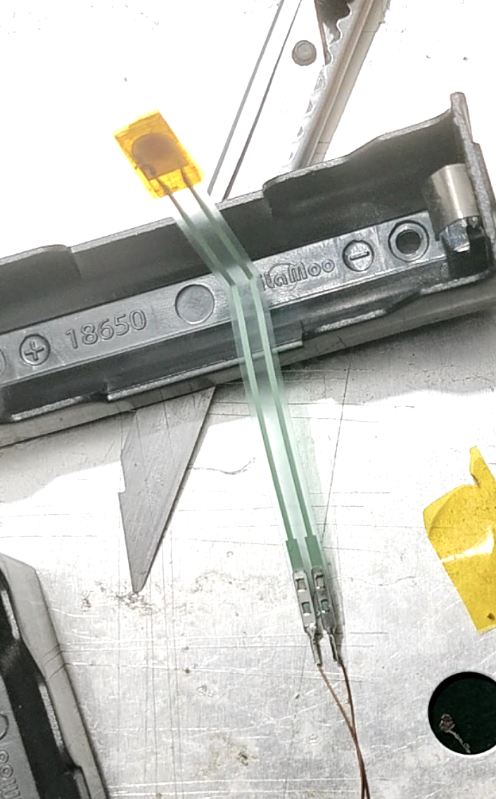
Next, process the sensor. Use two enameled wires to extend the sensor interface
. ![Screenshot_20240814_170757_com.hihonor.photos.png]

Then wrap the sensor head with tape twice to slightly increase its thickness (not too thick! Ensure that the sensor is not compressed when the battery compartments are not squeezed, even when the battery compartments are between them!)
. ![Screenshot_20240814_171040_com.hihonor.photos.png]
Then bend one of the pins of each of the two battery compartments at a 90° angle to install the motherboard. (Because the two battery boxes are connected in series, one needs to be bent to positive and the other to negative, as shown in the picture:
![Screenshot_20240814_172052_com.hihonor.photos.png]

Secure the sensor in the center of the battery box with tape. Fold the sensor wire as shown in the picture, with the connector perpendicular to the bottom of the battery box at a 90° angle, so that the connector is located in the gap next to the battery box to prevent interference with the pressure sensor.
![Screenshot_20240814_172628_com.hihonor.photos.png]
Then solder the two unbent pins of the battery box together, making sure that one is positive and the other is negative. (Ensure a reliable connection!))
![Screenshot_20240814_173423_com.hihonor.photos.png]

Thread another enameled wire through one of the gaps, solder it to this point, and lead it out as a battery balancing wire.
![Screenshot_20240814_173615_com.hihonor.photos.png]
Lead out one balancing wire and two sensor wires from the pin-side, cover the motherboard (note the positive and negative terminals! The Type-C side is positive!), and then solder the three wires to their corresponding pads. As shown in the image:
![Screenshot_20240814_174702_com.hihonor.photos_edit_1604295557941601.png]

Take out the previously processed motor ESC module. Connect the six enameled wires of the ESC to the motherboard as shown in the image:
![Screenshot_20240814_175757_com.hihonor.photos_edit_1604843523345038.png]

The connection is shown in the image:
![Screenshot_20240814_180658_com.hihonor.photos_edit_1605165271599967.jpg]
Then, shorten the two power cables of the ESC according to the distance and connect them to the motherboard. (Ensure a reliable connection!)
![Screenshot_20240814_181225_com.hihonor.photos.png]

Finally, connect the screen. As shown in the picture, the first pin is GND, and the remaining three are soldered in order.
![Screenshot_20240814_182708_com.hihonor.photos_edit_1606393204433092.png]

At this point, the circuit part of this project is complete. Place the screen facing the direction shown in the picture, and then connect the battery (pay attention to the positive and negative terminals! Connecting it backwards will burn it out!). Press and hold the power button for three seconds to turn it on:
![Screenshot_20240814_183421_com.hihonor.photos.png]
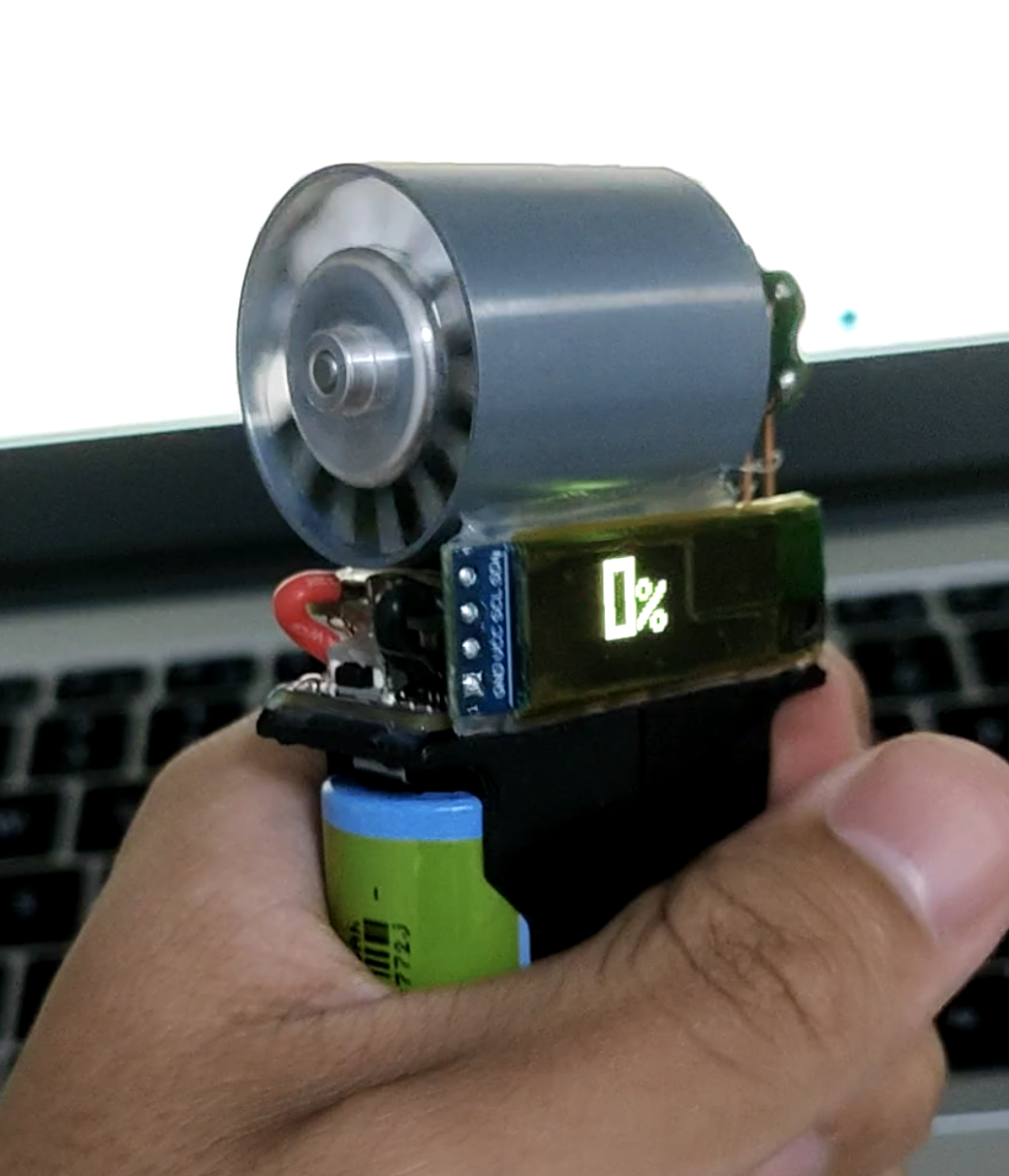
The PWM is not compatible during the first power-on; the speed range needs to be matched.
Setting the speed range:
1. Turn off the machine.
2. Plug in the charger. The machine will display a power-on icon
. 3. Immediately press and hold the power button. The power-on icon screen will pause for a longer time, followed by a special ESC setting tone after the ESC power-on tone.
4. Release the button. The screen will enter the normal charging interface. Wait for the ESC setting tone to end. The speed range setting is complete.
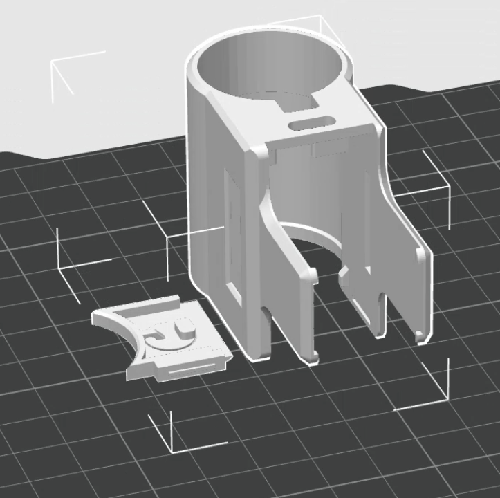
Next, print the machine casing. There are two documents (it is recommended to print them separately and set the button cover height to 0.1mm and the hole expansion to 0.4mm). Install them according to the pictures in the product description above. Then use soft glue (hot melt glue, silicone, glass glue, double-sided tape) to glue the casing to the battery compartment.
![Screenshot_20240814_185600_com.hihonor.photos.png]
Also, you can wrap the ESC with tape during installation for a neater look!
[Screenshot_20240814_190014_com.hihonor.photos.png]
At this point, the process is basically complete. However, the ESC has a default 10-minute inactivity alarm, which will cause the motor to keep making noise during charging. Therefore, the ESC parameters need to be adjusted.
This requires using a C8051 emulator or other devices with a C2 interface to connect to the ESC for parameter adjustment.
Connect the GND/V3.3/ck/cd interface of the fan debugging port
(there is a string of letters next to the debugging interface, GVPKDRT, which stands for GNDV3.3PWMCKCDRXTX)
. 1. Open the BLHeliSuite software
. 2. Select the Toolstick device (the software usually recognizes it automatically)
. 3. Click Read Setup to read the ESC parameters.
A pop-up window as shown in the image appears, indicating a successful connection
. [capture_20240814194258567.jpg]
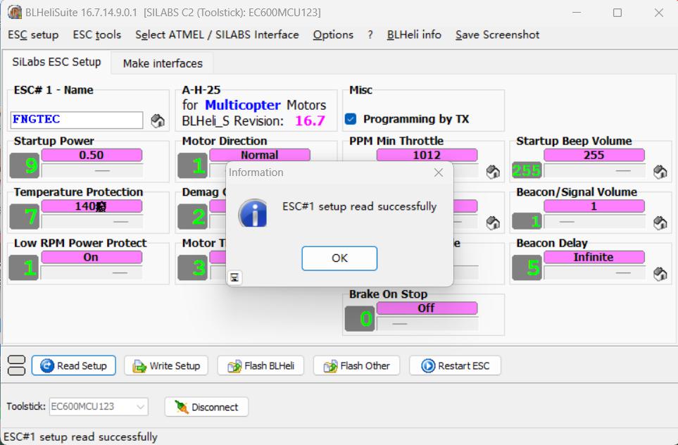
4. Adjust the three parameters circled in red in the image below to the parameters shown in the image. Leave the others unchanged.
(The first is the power-on volume, the second is the alarm volume, and the third is the alarm time. If you are interested, you can go to CSDN, where there are detailed tutorials for other parameters. Keywords: "blheli parameter tuning")
5. Click Write Setup to write the ESC parameters.
Parameter tuning is complete.
![capture_20240814194314007_精灵看图.jpg]

(5) Video tutorial
[Mini duct is open source! - Bilibili] https://b23.tv/DsD4rNN
(6) Join the QQ group for technical support:
General group: 439994627
Second group: 882184460
Third group: 374838945
Fourth group: 328881202
(7) Update notes
August 15, 2024 update:
The three pads with the tag number GVPKDRT, RS, and OLED1 do not need to be purchased. These three are just solder pads. You'll also need to purchase 2.54mm pitch, 3.5mm plastic height female headers separately; you can find them on Taobao.
August 19, 2024 Update:
Added the necessary tool "USB to TTL Downloader".
Added a link to a video tutorial.
mini duct accessories.zip
BLHeliSuite16714901.zip
mini duct accessories.zip
InteractiveBOM_PCB1_2024-7-5.html
PDF_[PD Charging] Mini Duct Grip Controller.zip
Altium [PD Charging] Mini Duct Grip Controller.zip
PADS_[PD Charging] mini ducted grip force controller.zip
BOM_[PD Charging] Mini Duct Grip Controller.xlsx
93037
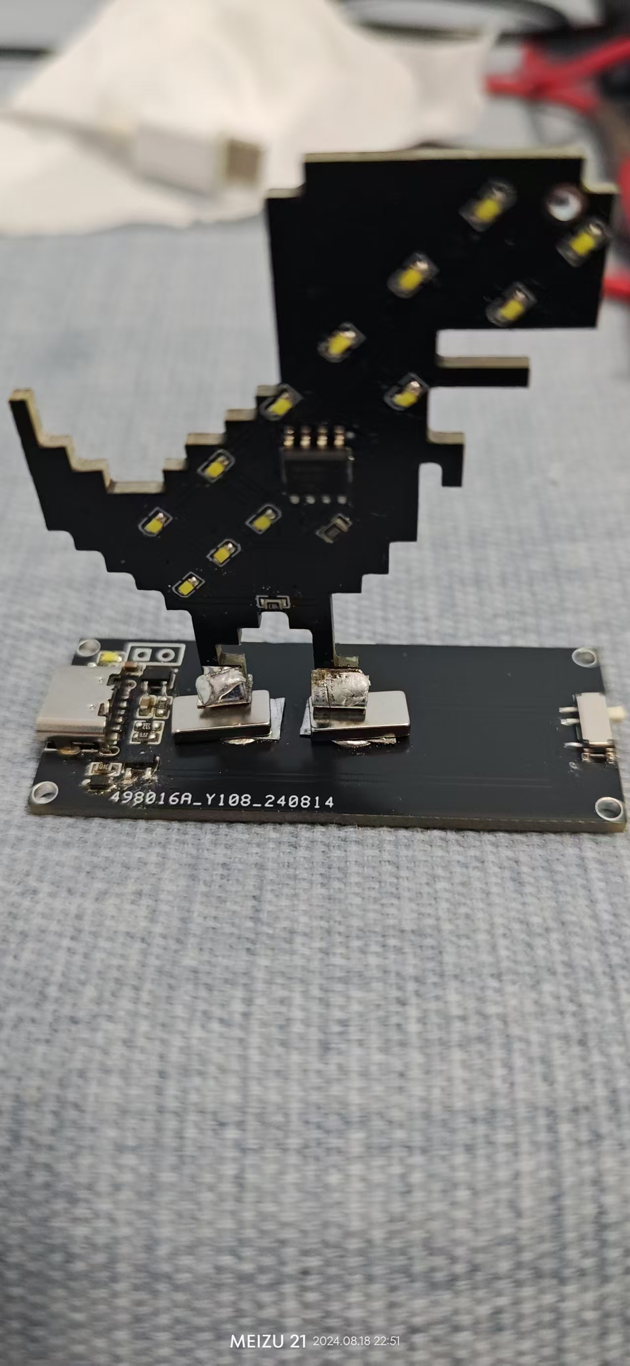
Meteor Dinosaur
The Meteor Light Google Dinosaur, designed using the TM1834.
I. Design Summary:
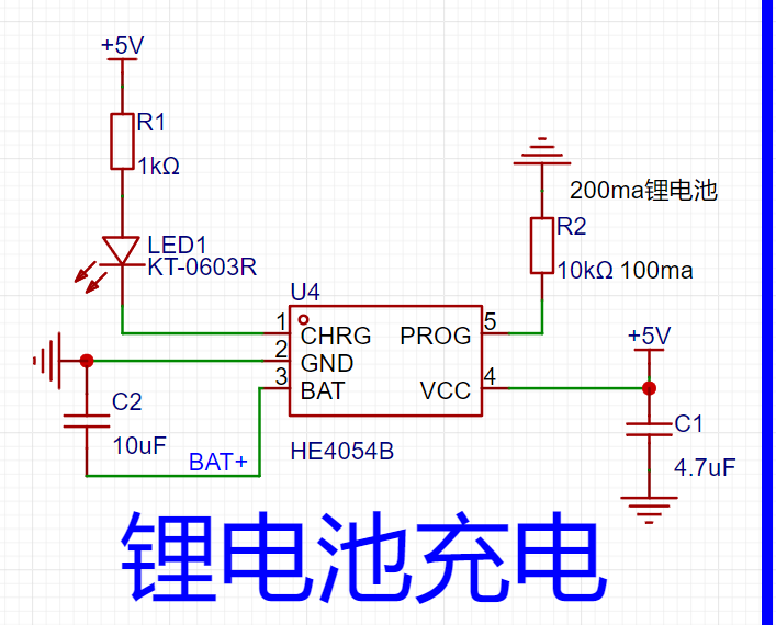
Primarily utilizes the HE4054B + TM1834 charging chips, allowing for battery-free operation at very low cost.
II. Hardware Circuit
: The charging circuit composition depends on the battery size, with the charging current designed accordingly. A standard 0.5C charging rate is achieved. The brightness of the
meteor effect driver IC can be adjusted by changing the resistance value of R7. III. Physical Demonstration: Red and white light effects are shown. The blue background causes the image to appear slightly bluish. IV. Installation Notes: The LED can be directly soldered on or magnetically attached using a sheet metal and magnet. (White LED is shown in the attachment .) V. Demonstration Video: White light effect video. Other colors are also possible, and color mixing is supported.


White light effect video 2.mp4
Red light effect video.mp4
White light effect video.mp4
PDF_Meteor Dinosaur.zip
Altium_Meteor Dinosaur.zip
PADS_Meteor Dinosaur.zip
BOM_Meteor Dinosaur.xlsx
93038
electronic


 京公网安备 11010802033920号

 IDT54FCT166H245ETPV


