As we all know, this year's Problem A relies on
the extremely complex AC-AC direct conversion, parallel connection of two machines without communication, and strange weight...
Let's get to the point:


Careful analysis of the problem reveals its core requirements:
1. AC-AC conversion, AC-DC-AC conversion prohibited
. 2. Droop current sharing (the two machines are only connected by power lines, i.e., communication is prohibited).
Upon closer observation, we find that the output voltage is always lower than the input voltage
. Therefore, we should build a buck-type AC-AC converter.
With a general direction (a buck-type AC-AC converter with droop control), we can search for relevant papers to find topologies and control methods.
Three topologies are suitable for our approach:
1. Folded bridge
: The AC input is folded into a pseudo-DC "bun" wave by a full-bridge converter, then inverted by a full-bridge converter to generate a sine wave.
The hardware architecture of this scheme is very simple, basically following the AC-DC-AC method.
However, after careful consideration, the "bun" wave seems too risky. If the reviewer thinks it's DC, it will be rejected.
Therefore, folded bridge, OUT!
2. AC using a bidirectional switch. Buck
uses back-to-back MOSFETs as bidirectional switches to replace the MOSFETs in ordinary buck converters, making it a bidirectional buck converter .
It can work normally in both the positive and negative half-cycles of AC, achieving the function of step-down.
However, bidirectional switches require isolated MOSFET drivers and isolated power supplies. We did not make the corresponding module
bidirectional buck converter beforehand, so it's out!
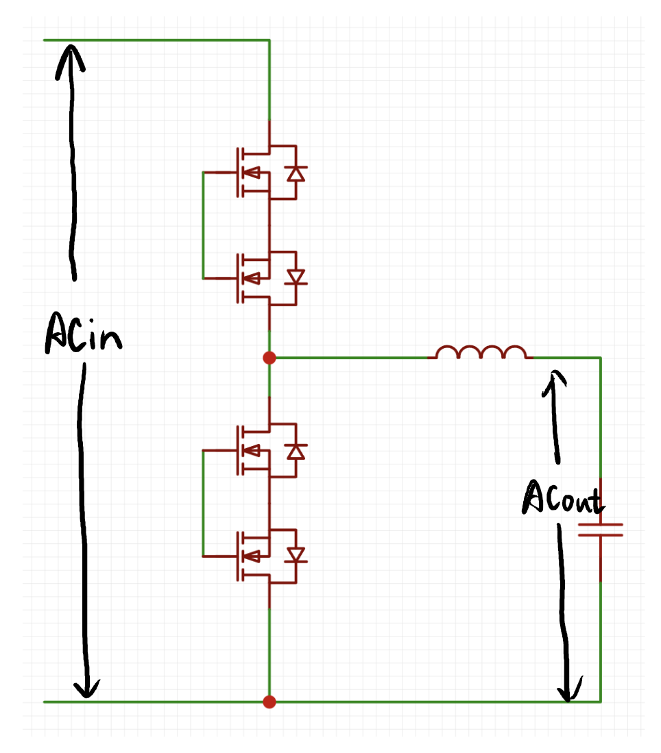
3. I'm too lazy to analyze the AC buck converter using ordinary half-bridge

. Once you
have the topology, you can consider the architecture of the entire system.
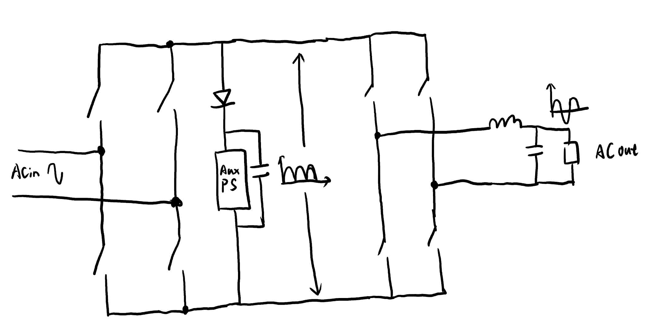
First, how should the auxiliary power be placed?
Since our auxiliary power is non-isolated, we must first determine the ground of the entire system
. We take the common ground of the two half-bridges as the system ground. We can see that the entire system becomes like this:
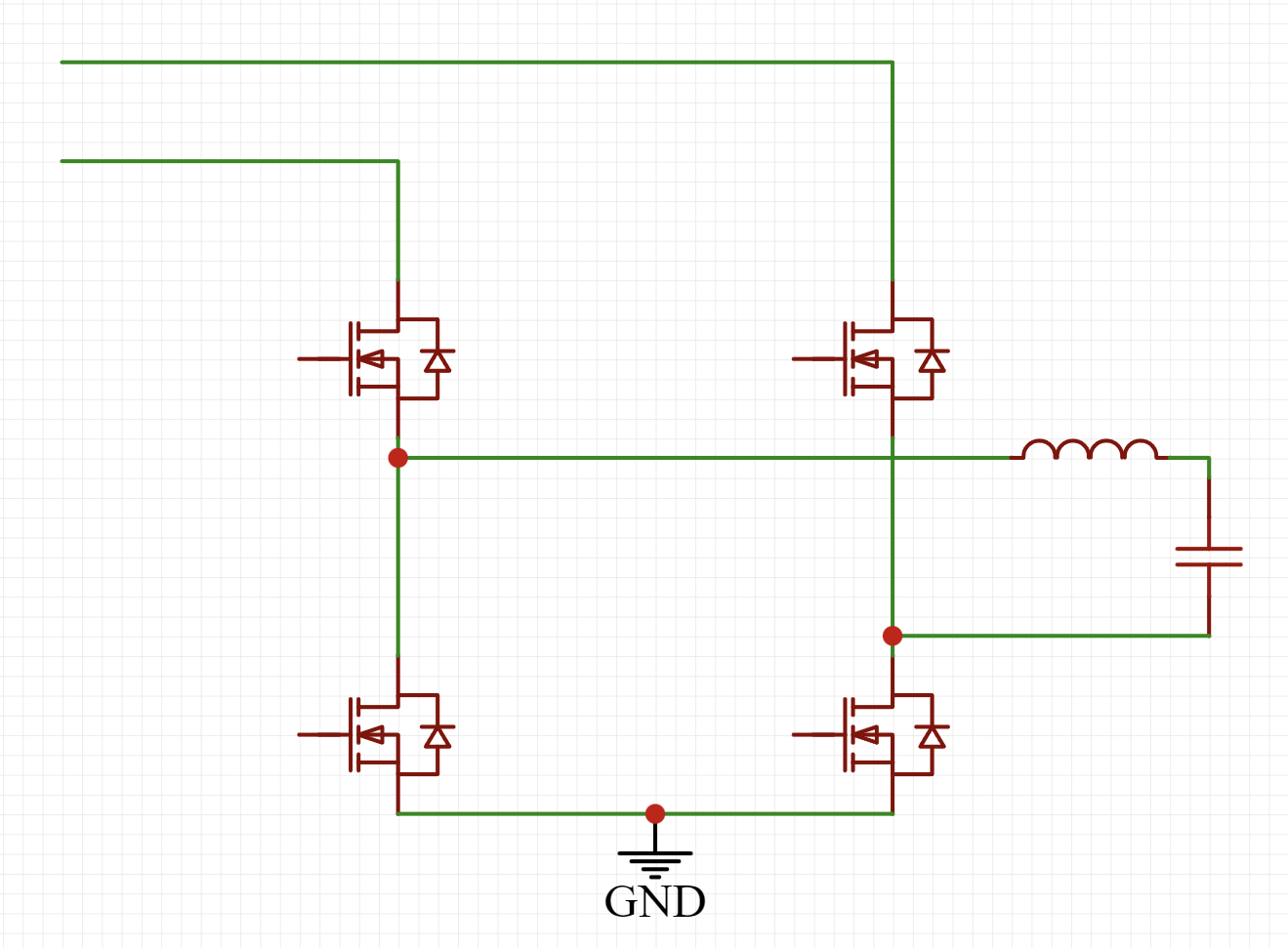
Isn't it clear at a glance?
So, regarding the placement and power supply of the non-isolated auxiliary power supply, I'll only provide this diagram here:

the red and blue arrows represent the current paths. You'll understand once you figure it out.
Next, regarding the measurement setup:
the quantities to be measured are input voltage, output voltage, and output current.
The input voltage is used for software phase-locked loop, the output voltage for the voltage loop, and the output current for the droop control loop.
This is simply based on the existing modules; it's very straightforward.
Finally, the control card:
it also uses the ground above as ground and the auxiliary power supply output as power. Just solder it on, and you're done.
Therefore, the hardware framework of the entire system is as follows:

Hardware Selection:
Don't look at this; it's just something I've done before... The remaining/inherited modules from this project, with all schematics open source, are too lazy to analyze (don't want to write an article QAQ).
Based on this, we optimized the layout to make it as compact as possible, and ultimately achieved a total weight of 560g for both machines.
Other specifications were basically met, resulting in first place in Hubei Province's A-level problem (doge).
Hint:
We used a gallium nitride half-bridge (six-layer board) for prototyping at JLC. Using a free coupon, we couldn't pass the review. Customer service said the board was too simple, with large copper surfaces on the inner layers, and suggested paying extra for a four-layer thick copper board. However, the 2oz surface copper thickness couldn't meet the minimum line width and spacing requirements.
As for whether this board is simple or not, you'll know the answer after seeing it.
Man, what can I say!
JLC OUT!


 京公网安备 11010802033920号

 1KS045-50GG


