Video Link:
[Bilibili Video - Function Demonstration and Introduction](【Desktop Ornament - Network Clock - STM32 - ESP01S】 https://www.bilibili.com/video/BV1vpmLYFEbE/?share_source=copy_web&vd_source=9018d111288e591392312c7d0a656c8a)
Project Introduction:
This project is a network clock based on the LCSC development board DiKuoXing STM32F103C8T6, using the RTX real-time operating system. It displays the time on a 4-pin IIC OLED, obtains the time from the network via the EPS01S, is powered by a lithium battery, and charges via a Type-C port. An alarm clock function is included, with the number of alarms controllable via macros and having no upper limit. An alarm is activated via a buzzer.
Project Functionality
This design is based on the network clock of the LCSC development board Dikuoxing STM32F103C8T6;
it has four independent buttons, and the function of each button is defined as follows: it can realize the adjustment of the alarm clock timer, and when the time reaches the set time, it will sound a buzzer to remind.
Clock interface button definition:
K1: View alarm clock 1~N (5)
K2: Turn on/off buzzer
K3: Turn on/off heartbeat light
K4: Undefined
K1K2: Undefined
K1K4: Restart
K3K4: Switch alarm clock interface
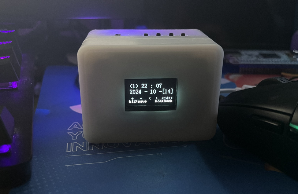
Alarm clock interface button definition:
K1: Add
K2: Subtract
K3: Move left to select
K4: Move right to select
K1K2: Save alarm clock
K1K4: Switch saved alarm clock
K3K4: Switch clock interface
Project Parameters
This design uses STM32F103C8T6 as the main controller;
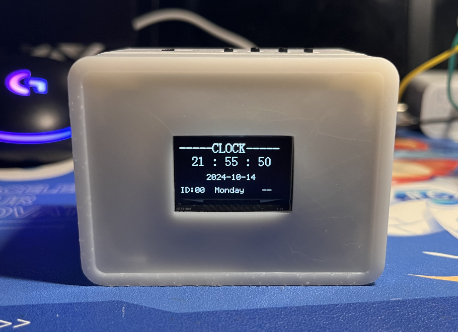
this design uses 4-pin IIC The OLED display shows the current time, date, and day of the week;
a buzzer is used for alarm clock notification;
the wireless module is EPS-01S;
it features four buttons, with various functions achieved through different button combinations;
an onboard LED serves as a heartbeat indicator, which can be turned off by a button.
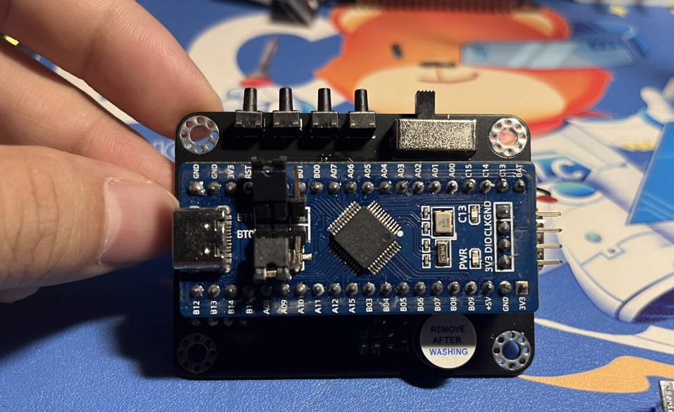
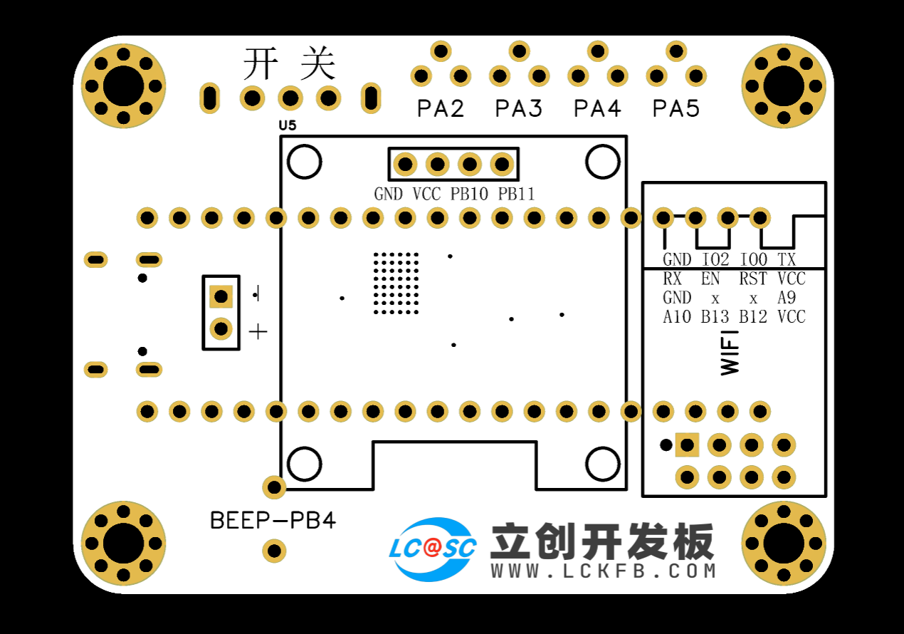
Hardware Explanation:

Main Control and Power Supply:
Utilizes an STM32F103C8T6 microcontroller with a TYPE-C-16P power

supply. Charging/Discharging Circuit:
Uses a TYPE-C-16P interface as the power supply interface, simultaneously charging the lithium battery. A switch controls whether to use lithium battery power. The circuit automatically switches to lithium battery power when the external power supply is disconnected, ensuring stable power supply.
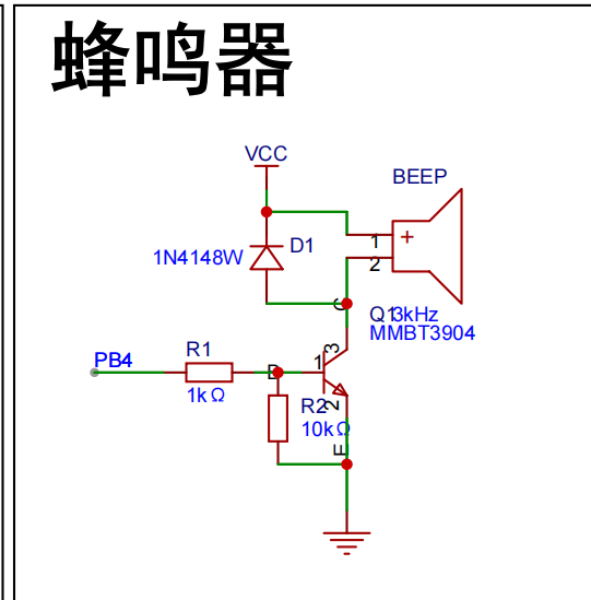
Buzzer Circuit:
The buzzer is controlled by the high and low levels of PB4.
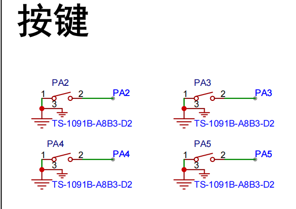
Button circuit:
Configured with four buttons, configured as pull-up input.
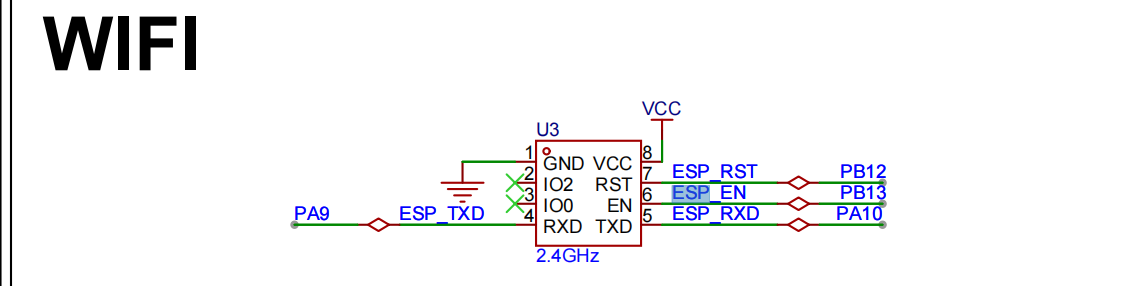
Wireless module circuit:
Connects to serial port 1, PA9, PA10.

Display circuit:
SDA connects to PB11, SCL connects to PB10, using hardware IIC driver
software code
. /**************************** STA mode ****************************/
//In STA mode, the hotspot the WIFI module needs to connect to (you need to modify it to your own parameters)
#define WIFISSID "ChinaNet-nkY6" //Wi-Fi hotspot name
#define WIFIPASS "97spky4v" //Wi-Fi hotspot password
Assembly process:
Flowchart of actual assembly
1. All modules
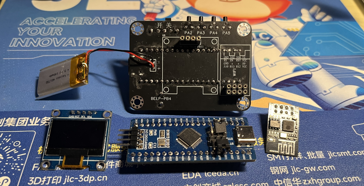
2. Install main controller
3. Packaging and battery protection

4. Install OLED and WIFI module

5. Power on and light up the chip

6. Install into the shell and screw in the screws Actual picture: Complete

actual
picture. For better aesthetics later, a panel can be added, with a pre-reserved groove.

V4-402_RTX_Network Clock.rar
PDF_Desktop Ornaments - Online Clock.zip
Altium Desktop Decor - Network Clock.zip
PADS_Desktop Ornaments - Network Clock.zip
BOM_Desktop Decor - Network Clock.xlsx
91685
electronic


 京公网安备 11010802033920号

 TC54VN2301ECBSTP


