Project Description:
The purpose of this project is to design and build a simple electronic game machine with specific entertainment functions based on microcontrollers, analog integrated circuits, digital integrated circuits, and discrete electronic devices.
Open Source License:
This project is licensed under the GPL 3.0 open source license.
Project Functions:
The target of this project is a simple electronic game machine with fixed entertainment functions. The game machine implements a simulation game of "explosive disposal," an evolution of the famous "Russian Roulette" game. In the game, the circuit system randomly selects a line that will trigger an "explosion," and two players take turns disconnecting the line within a time limit. The system determines whether an "explosion" is triggered based on the disconnection actions and displays the corresponding "explosion" effect. Since the "explosion" in this game is only simulated through sound and light, it poses no danger.
Project Attributes:
This project is my original work, being publicly disclosed for the first time. It has not been published in any public journal or as a graduation thesis before, and has not won any awards in other competitions.
Project Progress :
Currently, this project is fully completed, and a detailed description is provided here.
Design Principles
This project includes hardware and software components, enabling human-computer interaction with game participants, game content implementation, and game result presentation. The hardware component primarily consists of electronic circuit boards, composed of STC microcontrollers, analog integrated circuits, 4000 series digital integrated circuits, and basic discrete components. The software component is a microcontroller program written in C51, implementing functions such as random seed acquisition, external switch signal reading, countdown, win/loss logic judgment, and game result presentation. The hardware
component, with the STC microcontroller as its core, mainly includes a power supply, a microcontroller minimum system, a random number generator, external switch and connection status detection, a buzzer sound indicator, explosion sound playback, a game result indicator, and other auxiliary circuits. The system's functional block diagram is as follows:
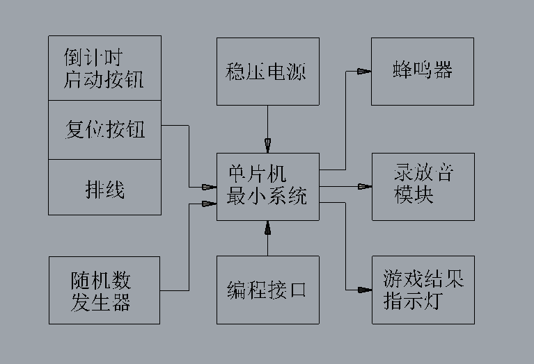
The descriptions of each hardware circuit are as follows:
1. Power Supply
This game console is a portable electronic device, therefore a 9V battery is used as its power supply. The power supply circuit includes reverse polarity protection, voltage regulation, and power indicator lights. The 7805 three-terminal voltage regulator provides a stable 5V DC voltage to the microcontroller and other circuit components.
2. Microcontroller Minimum System:
To achieve the required system functions, a microcontroller system is set up, including system reset and clock pulse functions necessary for normal operation. The microcontroller used in this project is an STC89 series microcontroller. The type and number of I/O ports meet the project requirements, facilitating easy program burning.
3. Random Number Generator:
To make the seed line that triggers the "explosion" in the game uncertain, thus enhancing playability, this project uses hardware circuitry to randomly select a value from 0-7 as the seed to trigger the "explosion." Specifically, a 555 timer is used to form a multivibrator, generating a clock pulse signal of a certain frequency as the counting pulse signal for the CD40192 BCD counter, driving it to increment. In addition, to limit the output value of the BCD counter CD40192 to the range of 0-7, the Q4 terminal of the BCD counter CD40192 is used in the circuit to reset the counter to zero so that the next round of counting can start, thus realizing the cyclic counting operation of the BCD counter CD40192. Therefore, when this part of the circuit is running, it will continuously output the BCD encoded value 0-7. When the microcontroller reads this value, it can obtain a value that is not fixed in the range of 0-7, which serves as the seed to trigger the "explosion".
4. External switch and wiring status detection
The button used to start the countdown and reset the system is connected to the microcontroller's port, allowing the microcontroller to detect the level of the port. The 8 sets of DuPont wires for the player to "disconnect" are directly connected to the microcontroller's parallel port, with the other end of the DuPont wires connected to GND, so that the microcontroller can detect whether the corresponding wire is disconnected by reading the level of the port.
5. Buzzer
The buzzer is used to emit an intermittent "beep-beep" sound as a prompt tone during the countdown in the game. In addition, to indicate whether "disconnecting the wire" during the game results in an "explosion" effect, a buzzer emits a continuous "beep---" sound to indicate the end of the game.
6. Explosion Sound Playback:
To enhance the gaming experience, this project uses a recording and playback module. When the game result is determined to be a "bomb explosion," the microcontroller drives the recording and playback module to play a pre-recorded "explosion" sound effect. The recording and playback module is externally connected to the main circuit board, with a corresponding interface reserved in the PCBA.
7. Game Result Indicator Lights:
This game uses one red and one green LED driven by the microcontroller to indicate the game result. When the disconnected wire is not the seed wire that "triggers the explosion," the green indicator light illuminates, indicating that the game continues; otherwise, the red indicator light illuminates, indicating that the game ends.
Software Description:
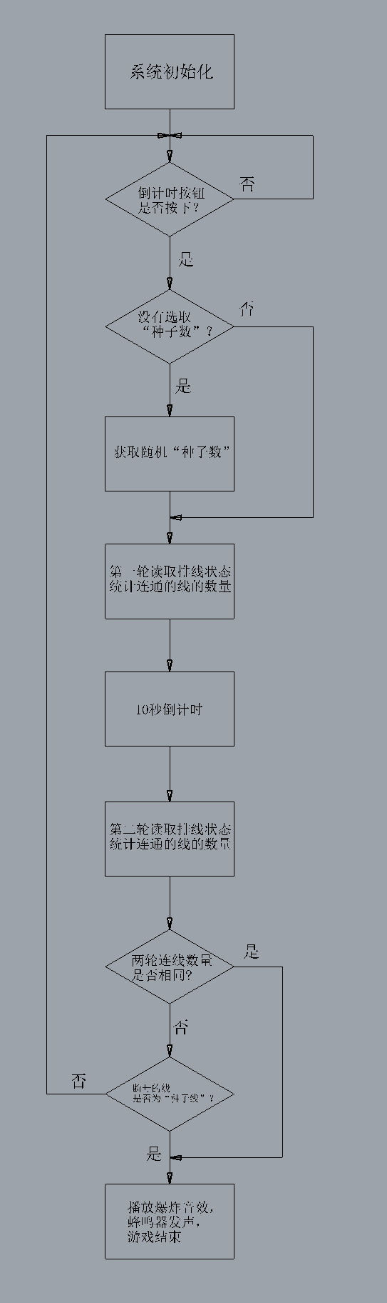
The software section is a program that implements functions such as randomly setting the seed wire to trigger the "explosion," determining the start of the game, reading the disconnection status, determining whether an "explosion" event has been triggered, outputting the buzzer sound, and controlling the recording and playback module. It is a C51 language program written for an STC microcontroller. The microcontroller program for this game console is attached. The software flowchart is as follows:
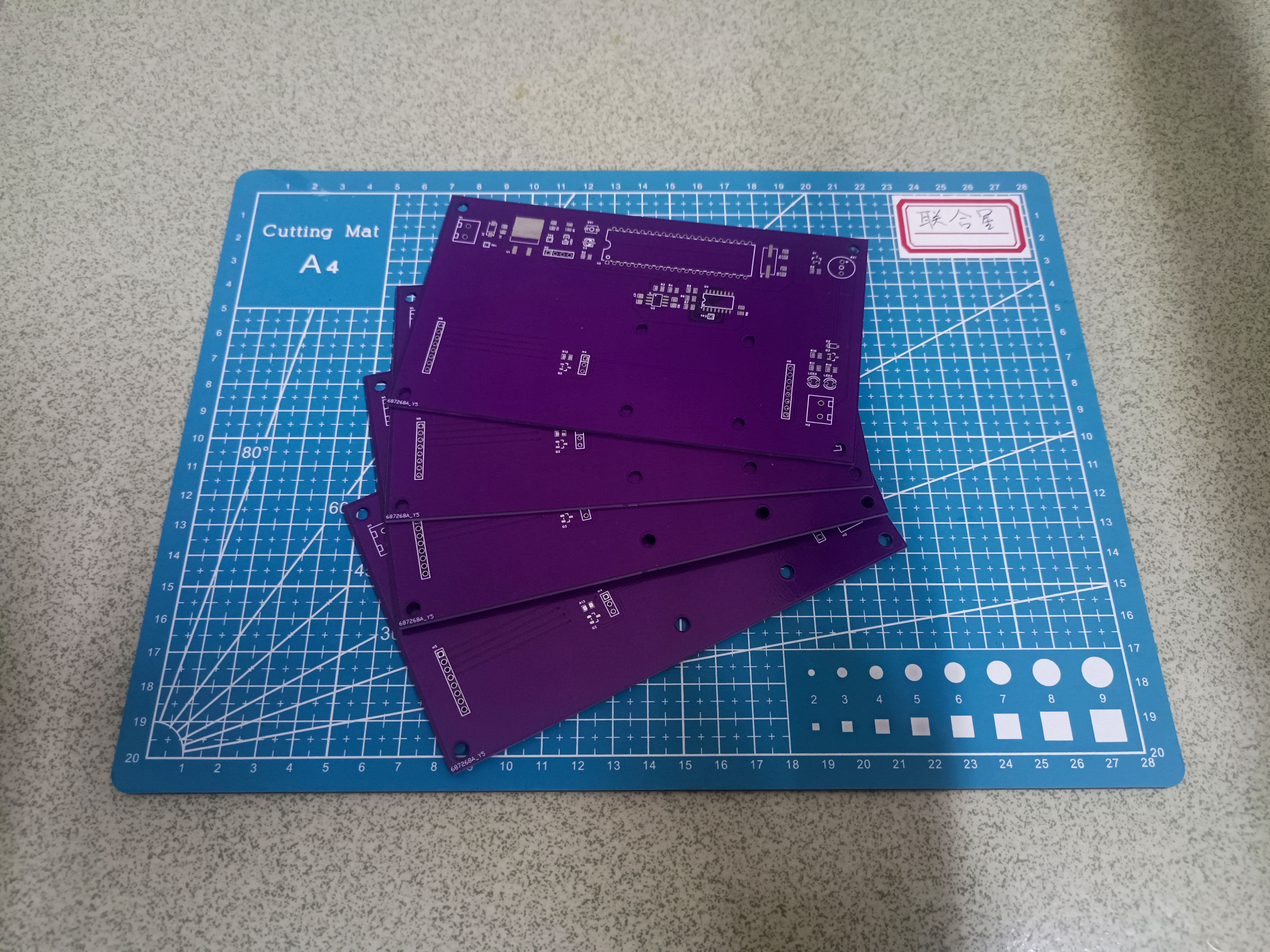
Physical demonstration
of the game console's appearance:

PCBA:
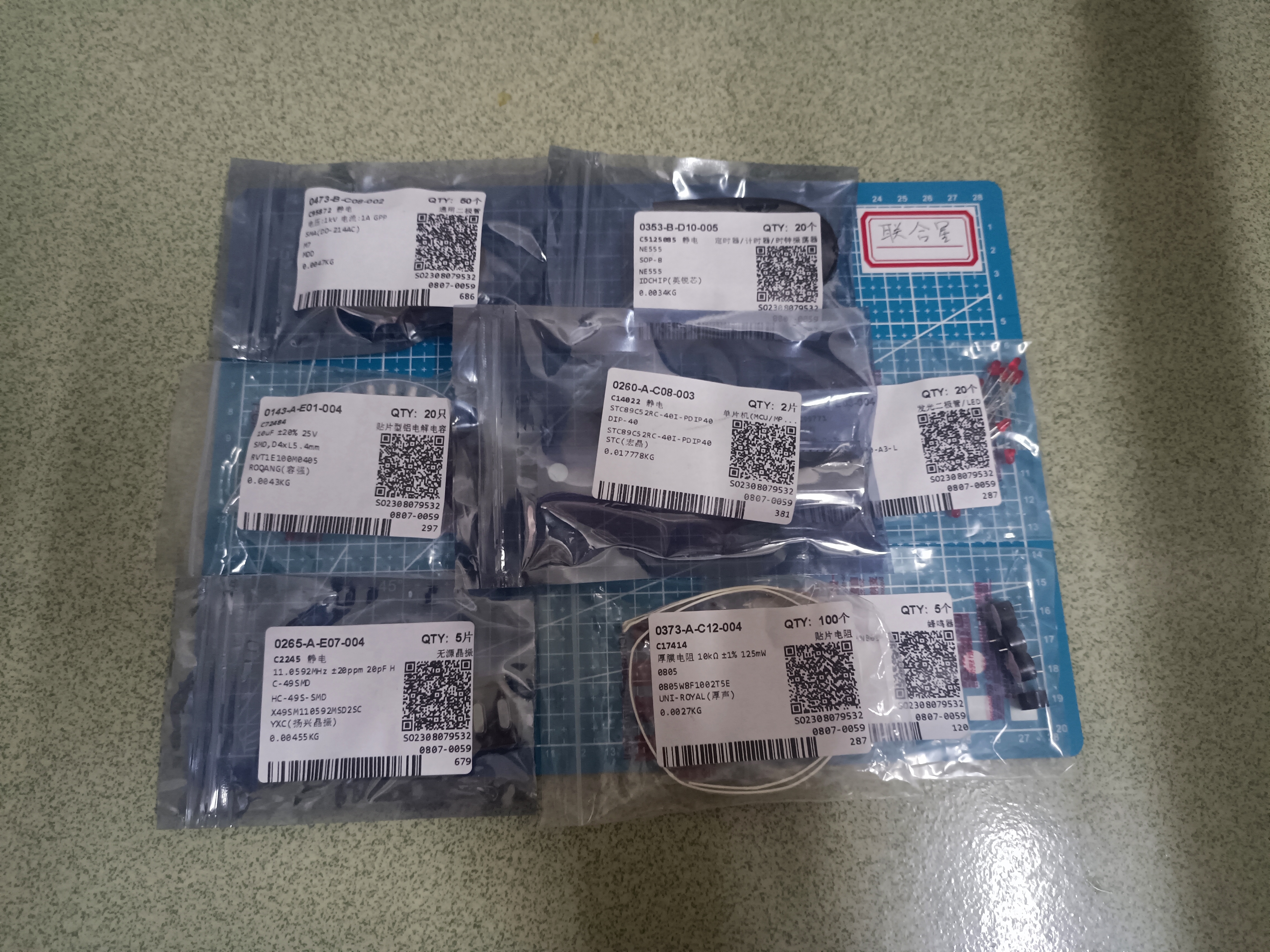
Electronic components:
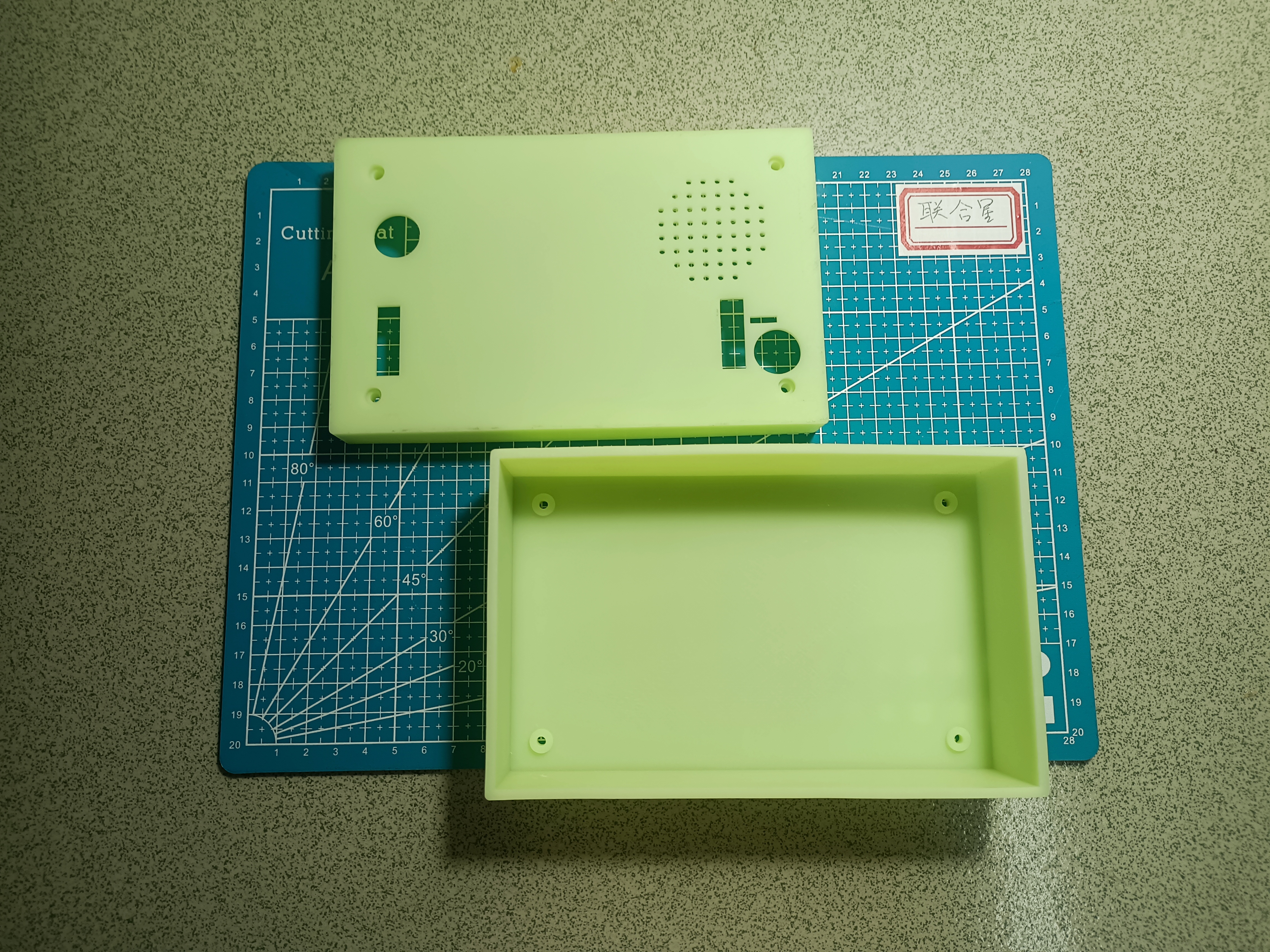
3D-printed plastic shell:
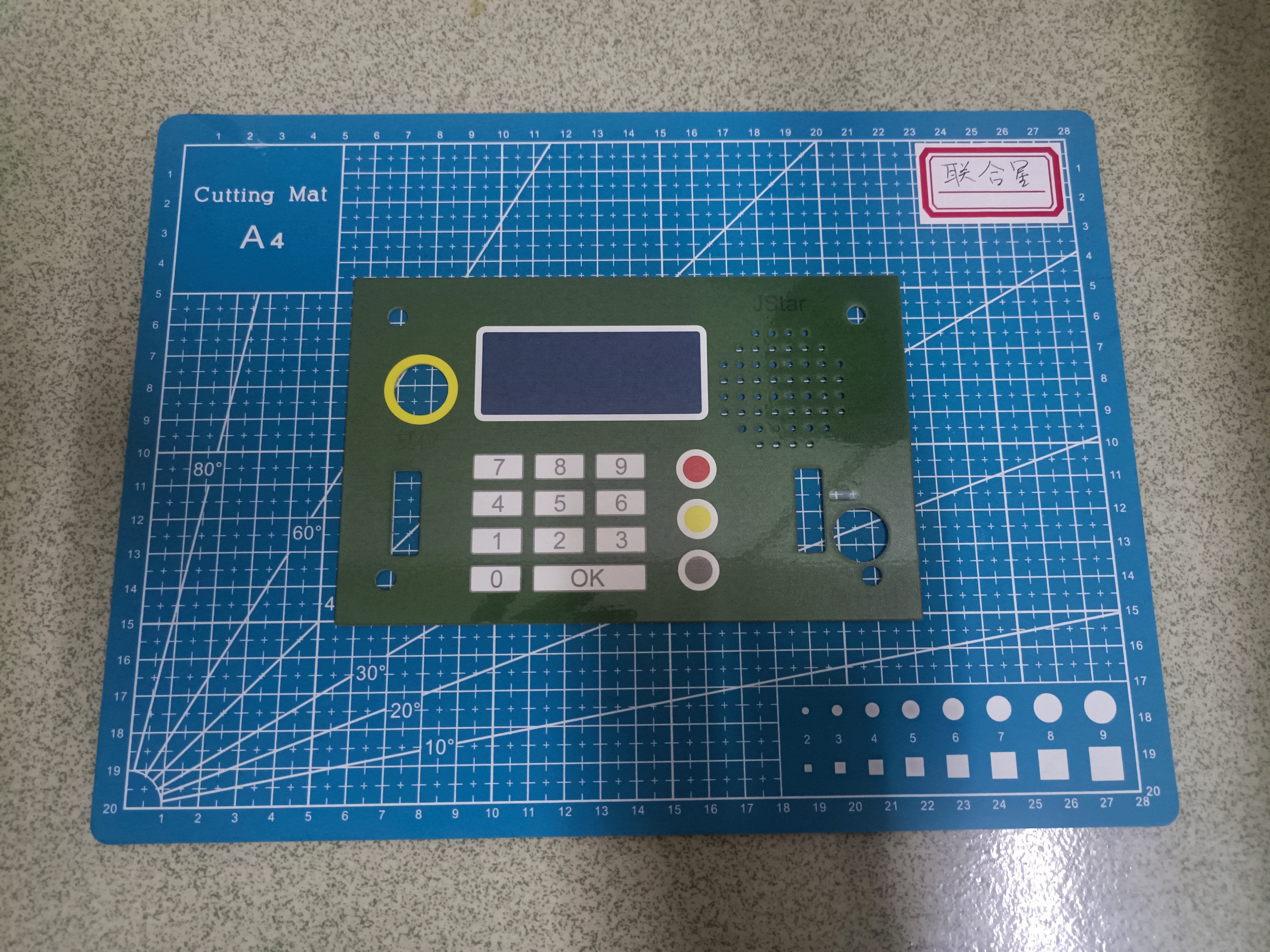
Acrylic panel:
Design Notes
:
Manufacturing Notes
1. The project relies on an external recording and playback module to play pre-recorded sounds. The main circuit board has corresponding interfaces, and the recording and playback module is fixed to the main circuit board via nylon pillars;
2. Components required for normal operation, such as the 9V battery, countdown start button, reset button, and ribbon cable, need to be external and are not included in the PCB.
3. The test ring TP on the circuit board is not a necessary component for circuit operation.
Other
demonstration videos:
1. Game console operation demonstration (verification) video link:
https://www.bilibili.com/video/BV15b4y1M79r/
2. Principle explanation video link:
https://www.bilibili.com/video/BV1ZG411i7e1/


 京公网安备 11010802033920号

 U732121366


