--------------------------------------------------------------------------------------------------------------------------------------------------
----------------------------------------------------------------------------------------------------------------------------------
--------------------------------------------------------------------------------------------------------------------------------------------------
------------------------------------------------------------------------------------------------------------------------------------------------------------------
Experimental STC8051U - Replication Challenge. This project replicated the STC8051U using JLCPCB EDA, based on the official schematic and PCB layout. (STC8051U 7/1)
STC8051U Global University Program Experiment Box Replica
STC8051U-PCB-Electronic_experimental_box_V-replica
Project Errata and Optimization (July 21, 2024) (Version V20240712 Revision) Due to the large amount of content, only a few are listed here. For detailed illustrations, please refer to: https://www.stcaimcu.com/forum.php?mod=viewthread&tid=9406&extra=&page=3
V20240712.01 Optimization of PC1-USB+5V power supply circuit; V20240712.02 Re-layout of PCB according to the latest schematic and reference bitmap of STC's official V20240712 version; V20240712.03 Added a shorting circuit from the negative input to the output of U13 op-amp. The official version left it floating, which may be a typo (previous versions all had feedback on the negative input of the op-amp).

Tips: The V1.7 small demo program can be found by searching the forum
for engineering errata and optimizations (June 30, 2024) (V1.7 version revision). Due to the large amount of content, only a few are listed here. For detailed illustrations, please refer to: https://www.stcaimcu.com/forum.php?mod=viewthread&tid=9250&extra=&highlight=stc8051U&page=2
1.7.01 Optimized PC1-USB+5V power supply circuit; 1.7.02 On-board support for OLED/TFT/RGB/IPS devices >0.96 inches (rotated slightly in V1.7); 1.7.03 Optimized MCU VCC and GND routing, moved the filter capacitor closer to the MCU VCC pin; 1.7.04 Silkscreen optimization, especially for rear pins, most header pins now have added silkscreen descriptions; 1.7.05 Optional hardware components are now packaged with jumper pads for easy identification; 1.7.06 1.7.07 Added a ring conductor by placing a stitching hole at the edge of AGND. 1.7.08 Increased the distance between the AGND and GND junction. 1.7.08 This plan was not completed. Reason for not completing the adjustment of the Type-C position: If the position is adjusted (J20 and TF card swapped), the RF socket will also affect the normal insertion of J20. If the position is adjusted (J3 moved down), it will affect installation into the casing. If the position is adjusted (TF card placed on the back), the casing needs to be considered. Feasibility is pending.
1.7.09 Added a teardrop. 1.7.10 Revised the schematic diagram. Note the 2.4 TFT power supply. Originally, there was redundant design here.
Engineering errata optimization (June 29, 2024) (V1.6 revision). There is a lot of content, so only a few are listed. For specific illustrations, please refer to: https://www.stcaimcu.com/forum.php?mod=viewthread&tid=9250&extra=&highlight=stc8051U&page=2
1.6.01 The frame was corrected to a standard 166.0 mm x 99.4 mm, four corner mounting hole diameter is 3.5 mm 1.6.02 Modified LCD12864 device to be compatible with the original STC teaching video physical object, and corrected the corresponding position and orientation 1.6.03 Modified LCD1602 device to be compatible with the original STC teaching video physical object 1.6.04 Revised 2.4-inch TFT device to be compatible with the original STC teaching video physical object, and established a private package, which has been shared to the EDA platform, and the schematic diagram has been updated synchronously 1.6.05 Added compatibility support for 0.91-inch IIC bus screen 1.6.06 Added compatibility support for 8-pin screen OLED/IPS/TFT, and synchronously added hardware control CS and BLK pins, so that P1.1 and P5.0 can be released for use (actually, the BLK pin is controlled by high and low level, high level turns on the backlight (default), low level turns off the backlight) (CS pin is controlled by high and low level, high level releases chip select, low level selects the device) 1.6.07 Added DS18B20 one-wire single bus The experimental hardware foundation for mounting multiple devices 1.6.08 adds DHT11, which is similar to DS18B20 in a one-wire single-bus experiment. It runs in parallel with DS18B20, but the selection is differentiated by hardware resistors. 1.6.09 Fixes the issue where the STC8051U cannot be powered when the Type-C_J20 is inserted alone (this applies the principle of diode priority conduction; due to voltage drop considerations, parameters of 1A~3A are preferred to ensure that the downstream load does not draw too much current). 1.6.10 Revises the 4-digit LED display device number C132660 (previously a blind selection; this time it is updated based on a physical sample seen by forum members). 1.6.11 Revises the infrared receiver tube device number C16216, considering wavelength and driving frequency (referencing teaching videos and example programs). 1.6.12 Modifies the NTC section to be compatible with PTC, photoresistors, and other similar resistance change sensors, but the selection is differentiated by hardware resistors. 1.6.13 Revised BAT battery device part number C5365933, affecting cost and 3D rendering display 1.6.14. Revised KEY device part number C118141, affecting cost and 3D rendering display 1.6.15. Revised the 2.4-inch TFT package to fully conform to the actual size 1.6.16. Fixed the Q4 error; in version V1.1, Q4 selection was incorrect 1.6.17. Added MCU CORE section, enabling quick PIN testing or application replacement 1.6.18. Corrected the crystal oscillator pin network error in the schematic diagram 1.6.19. Revised the SRAM package IS62C256AL; pad lengthened for compatibility with narrow/wide chips 1.6.20. Revised the 74HC573 package, compatible with 208mil and 300mil; pad lengthened for compatibility with narrow/wide chips 1.6.21. Revised the LCD12864 VDD (PIN2) pin, allowing selectable 5V/3V3 power supply 1.6.22. Revised the LCD12864 PSB pin, hardware selectable high/low level, enabling serial/parallel selection. 1.6.23 Revised toggle switch pins C2875122 and C500055, related to cost and 3D rendering display. 1.6.24 Fixed C58, selected C1206 package according to the schematic, and marked the withstand voltage (250V) on the PCB. 1.6.25 Revised S6 direction, related to layout routing difficulty. 1.6.26 Revised w1 pin, related to layout routing difficulty. 1.6.27 Added filter capacitor for U11, as the author separated the power supplies for U10 and U11 due to layout, requiring separate filter capacitors. 1.6.28 Fixed silkscreen obstruction issue. 1.6.29 Designed silkscreen for toggle switches/tactile switches to facilitate related experimental operations for users of the experimental box.

Engineering errata optimization (June 21, 2024) (LCD) The PS8 silkscreen has been changed to PSB, and 3D model display has been added (6mm adjustable capacitor in plastic package, OLED/7PIN, TFT, LCD). To independently display onboard components, please only see the 3D optimized
PCB_V1.0_1 for the display devices:
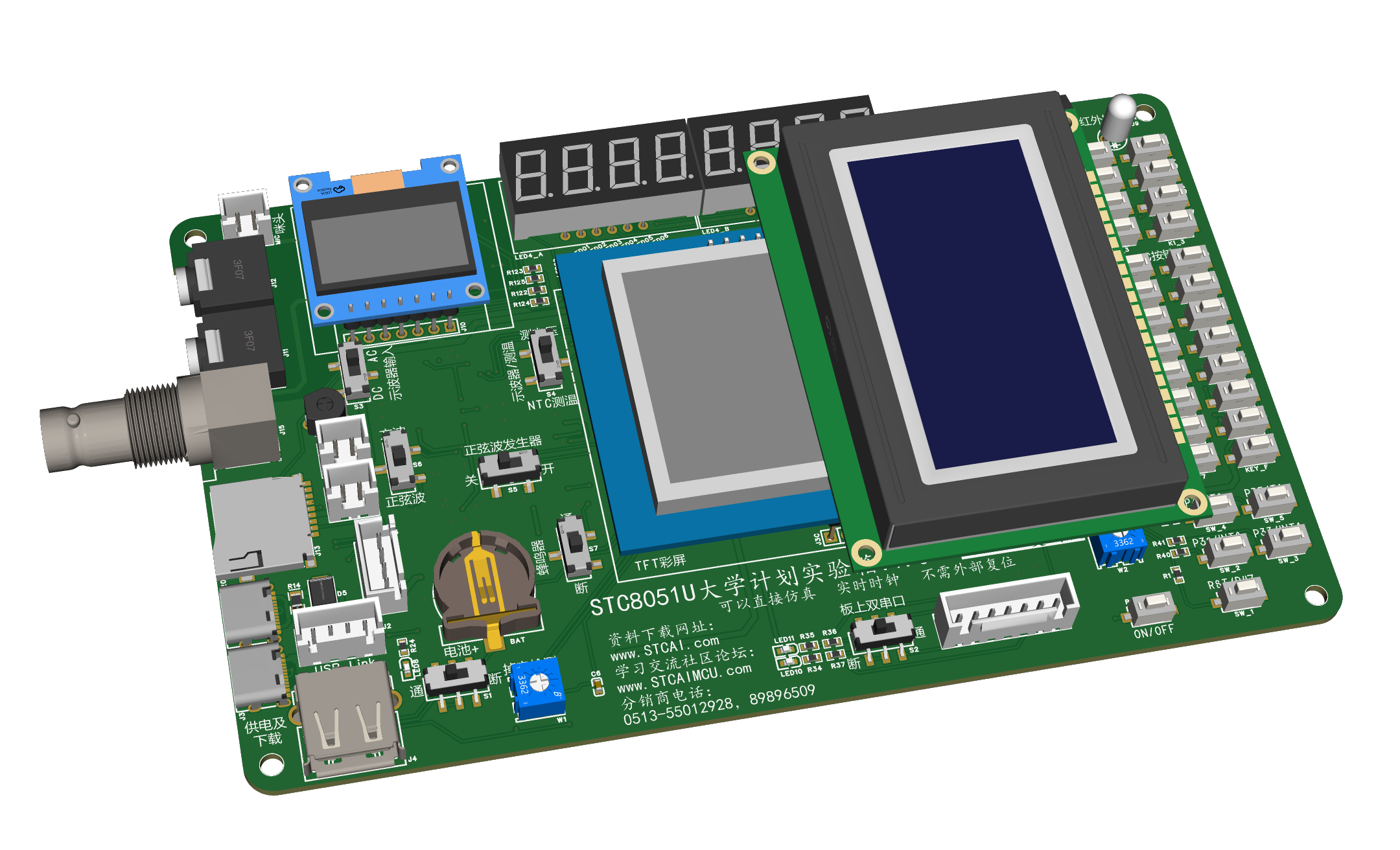
PCB_V1.0_1:

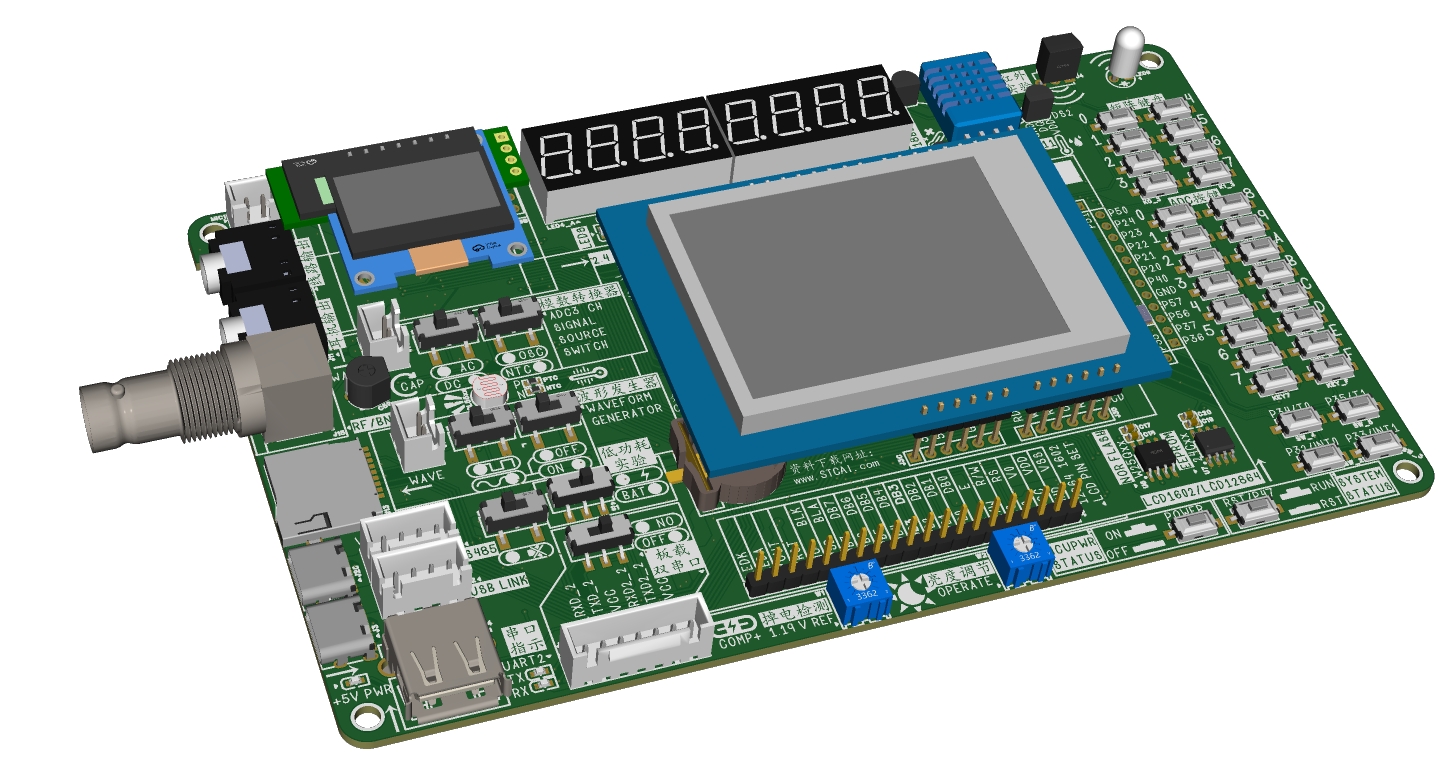
This project is replicated from the STC8051U Global University Program experimental box, built according to the official schematic and reference PCB.
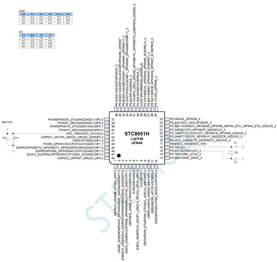
The onboard main controller is the STC8051U-LQFP48 chip!!
Official event link: https://www.stcaimcu.com/forum.php?mod=viewthread&tid=9055&page=2#pid86899
STC experimental box data link: https://www.stcai.com/syx
(The STC8051U chip on the replicated experimental box is officially scheduled for release on July 1st; related development boards and experimental boxes are expected to be released at the same time.)
The experimental box replicated in this project contains the following modules/circuits: USB download/simulation circuit, comparator power-down detection, buzzer, running light, RS-485 communication, dual serial ports, independent buttons, row and column scanning buttons, 1-channel ADC detecting 16 buttons, SPI expansion 74HC595 driving 8 eight-segment LED displays, QSPI/SPI serial FLASH, 2-wire I2C-EEPROM, 1-wire temperature sensor DS18B20, OLED12864, traditional three-bus, TFT color screen + touch, LCD12864/ LCD1602, TF card, oscilloscope, waveform generator...
 --------------------------------------------------------------------------------------------------------------------------------------------------
  ----------------------------------------------------------------------------------------------------------------------------------
  --------------------------------------------------------------------------------------------------------------------------------------------------
  ------------------------------------------------------------------------------------------------------------------------------------------------------------------


 京公网安备 11010802033920号

 CDC7005ZVAT


