Project Description:
The entire unit adopts an industrial control style design, making operation simple and clear, and ensuring safe and stable use.
The temperature control device uses an intelligent industrial temperature controller with PID control, eliminating the need for user firmware programming and maintenance, saving time
and effort. The heating element uses a new type of industrial-grade MCH high-temperature ceramic heating element, which boasts advantages such as rapid heating, high temperature, environmental friendliness, and safety.
The internal circuit structure is simple and easy to replicate; only basic electronics knowledge and strong hands-on skills are required for successful construction.
Note: Those who already have PTC or PD heating platforms can refer to the heating board solution in this project, purchase suitable MC ceramic heating elements, and upgrade their existing heating boards with almost no modification to the original control circuit.
Enthusiasts who enjoy learning and tinkering can also design their own microcontroller control board circuit to create more personalized heating platforms.
The project
features two heating modes: freely switchable constant temperature heating and segmented heating (simulated reflow soldering).
The heating board can easily reach temperatures above 300℃, posing no problem for soldering or desoldering circuit boards using high-temperature solder.
Adjustable key point temperature to adapt to the soldering temperature requirements of different solder pastes, with wide applicability and high soldering quality.
A forced cooling switch is designed, allowing users to interrupt heating at any time and simultaneously activate the cooling fan for forced cooling; the concealed design reduces the risk of accidental operation.
The heating plate size can be freely planned; simply adjust the specifications and quantity of the ceramic heating elements according to the heating plate volume, making it simple and convenient.
It can be used as an SMT segmented heating station, a constant temperature desoldering station, mobile phone heating layering, heat shrink film encapsulation, hot air heater, etc.
Open source license
CC-BY-NC-SA 4.0.
Please indicate the original link when reprinting .
Project attributes:
This project is being publicly released for the first time and is my original work. This project has not won any awards in other competitions.
Update log:
2024.09.27 Newly uploaded drawings of the CNC heating substrate and corresponding aluminum-based fixing plate.
2024.10.10 Changed the board-to-board connector direction between the control board and the power board to correspond to the wiring sequence in the BOM.
Design Principles
I. Circuit Design Principles:
1. Power Board
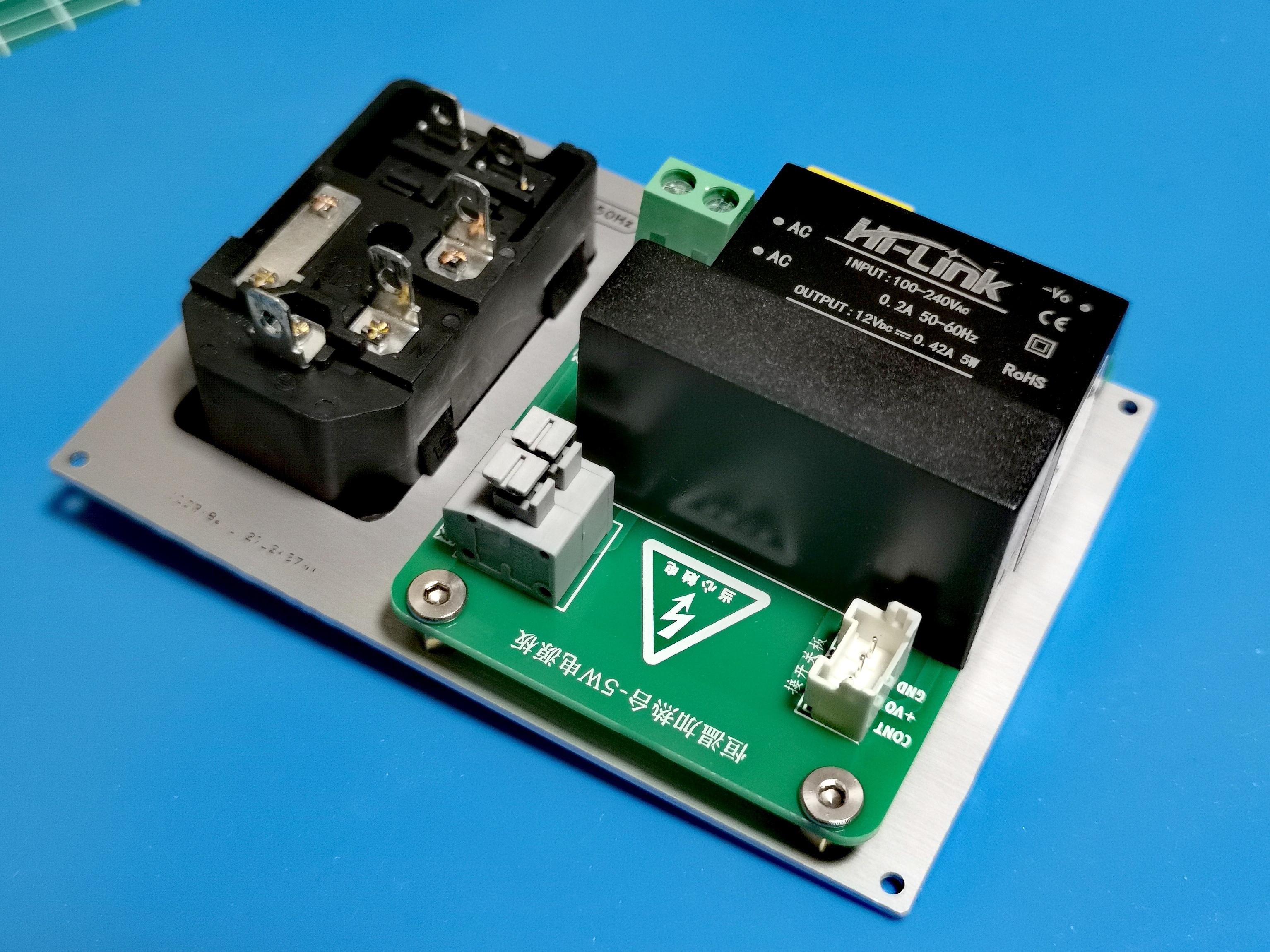
The power board circuit is shown in the diagram below. The 220V voltage input from CN2 is directly converted from CN1 to the 220V power terminal of the temperature controller. The other path is converted to 12V DC voltage via the AC-DC power module (U1) and output to the switch control board through pin CN3_2. U2 is a PCB solid-state relay (DC-controlled AC type). The DC control signal from the switch board is input to the input terminal of the solid-state relay through pin CN3_3, while the 220V ceramic heating element is connected to the output terminal of the solid-state relay through CN4.
Notes: The models of the PCB solid-state relay (U2) and AC-DC power module (U1) must be selected according to actual needs. The models marked in the diagram are only suitable for heating elements with a maximum power consumption of less than 1000W and cooling fans with a power of less than 5W. U0 is a surge protector varistor used to protect the power module, and C0 is a 275V safety capacitor. C0 and U0 can be selectively installed depending on the usage environment (not required in household environments).
5W AC power board circuit diagram and 3D preview:


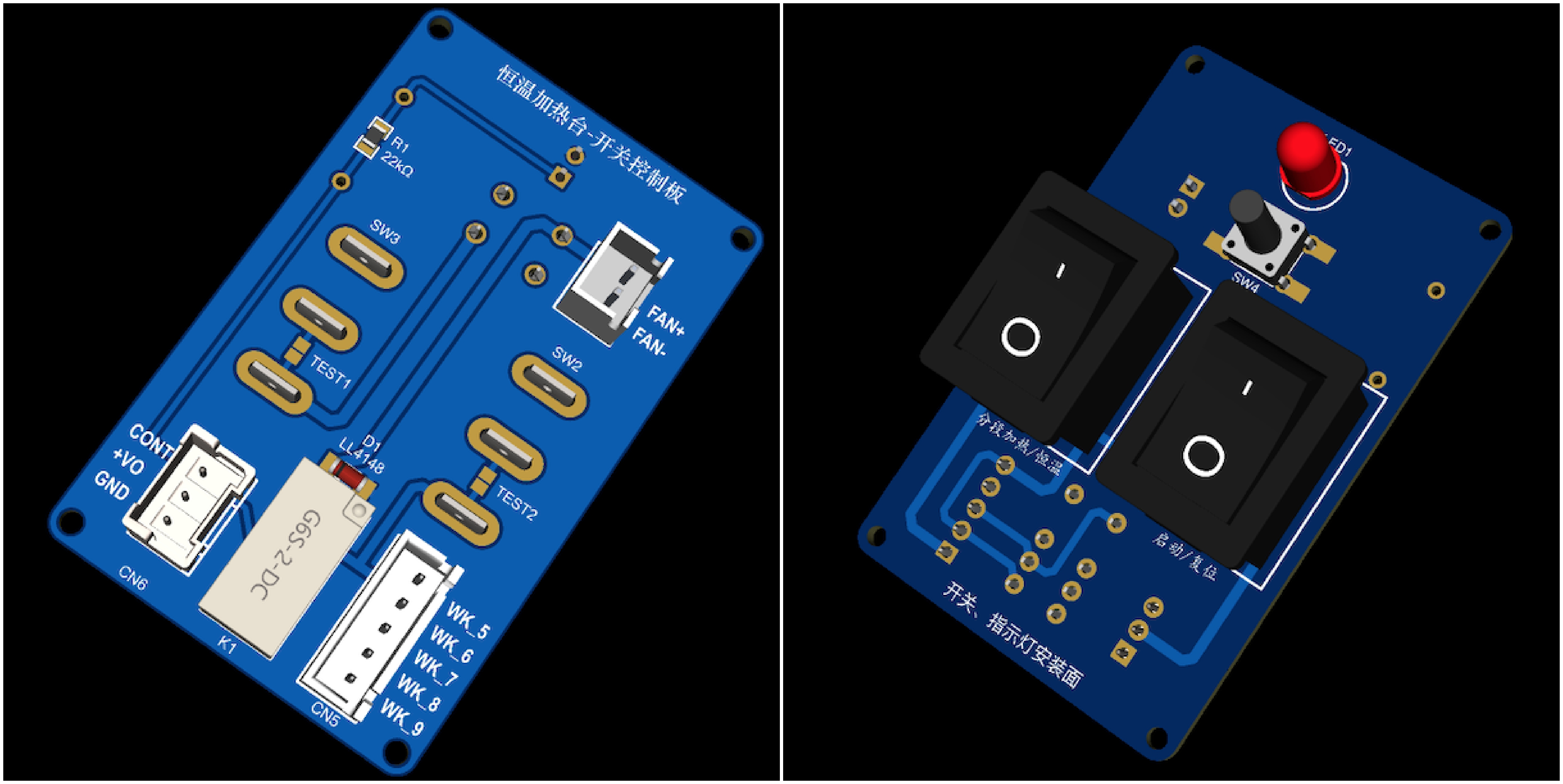
2. The switch control board
is shown in the figure below. SW3 is the start/reset switch, SW2 is the mode switch for segmented heating/constant temperature heating, and SW4 is the manual forced cooling switch. Users can interrupt heating at any time and turn on the cooling fan to force cooling of the heating plate. K1 is a signal relay, which switches the control signal and connects to the temperature controller, power board, and cooling fan respectively via CN5, CN6, and CN7. LED1 is the heating status indicator.
Switch control board circuit diagram and top and bottom 3D preview:

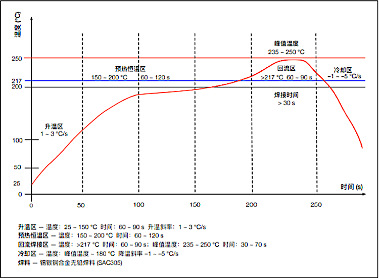
II. Design principle of segmented heating function
The design principle of the segmented heating function in this project is based on the "sloping reflow soldering temperature curve" shown in the figure below. The figure has clearly marked the "temperature-time" requirements of the "preheating zone, constant temperature zone, reflow zone, and cooling zone", and most solder pastes can be used in these temperature zones. Therefore, as long as the temperature rise rate of the heating plate can be controlled within the required range of each temperature zone in the figure, good soldering quality should be obtained.
Ramp-type reflow soldering temperature curve:
III. Working principle of the constant temperature heating table:
If cost is not a major concern, the simplest control scheme for segmented heating is to use a "programmable segment temperature controller" as the core component of the temperature control circuit. For hobby purposes, wouldn't it be great to have a cost-effective heating table that's easy to build, requires minimal technical knowledge, and requires minimal maintenance (ideally, a one-time solution)? This project is an alternative design based on this goal, using a common intelligent temperature controller to achieve segmented heating.
Reset mode: When the power switch SW1 is closed, the temperature controller is powered on. When SW3 is in the reset position, there is no output from any of the temperature controller's output terminals, and the heating plate and fan will not work. This state facilitates setting the temperature controller's parameters. Constant
temperature mode: First, set the preset temperature of the temperature controller according to your needs. PLM2 must be set higher than the preset temperature. Then, place SW2 in constant temperature mode. In this mode, the PLM1 signal is disconnected from the circuit by SW2, and PLM2 also has no output because it is higher than the preset temperature. The heating plate temperature is controlled solely by a temperature controller, and the temperature is kept constant within the preset range.
Segmented heating: Referring to the data in the "Incremental Reflow Soldering Temperature Curve" (using a commonly used medium-temperature lead-free solder paste as an example), first set the temperature controller's preset temperature to 200ºC, PLM1 to 195-200ºC, and PLM2 to 245-250ºC. (This step is crucial! In actual use, adjustments can be made according to the soldering temperature of different solder pastes.)
Set SW2 to segmented heating mode and activate the segmented heating mode of the heating platform.
Preheating zone: The heating platform starts heating from room temperature. When the detected temperature is significantly lower than the temperature controller's preset temperature (200ºC), the temperature controller's PID circuit is almost inactive. During this stage, the free temperature rise rate of the heating plate meets the temperature rise rate requirements of the "preheating zone."
Constant temperature zone: When the detected temperature reaches approximately 140-160ºC, the temperature controller's PID circuit begins to operate, gradually reducing the heating plate's temperature rise rate to avoid temperature overshoot. Simultaneously, due to the positive temperature characteristic of the MCH ceramic heating element, the resistance of the heating plate gradually increases with temperature. Therefore, the temperature rise rate of the heating plate gradually decreases during this stage, and the temperature curve becomes flatter. Under the control of the PID circuit, the heating plate temperature rises slowly until it reaches the preset 200ºC. During this stage, the temperature rise rate of the heating plate is more in line with the temperature rise rate requirements of the "constant temperature zone".
Recirculation zone: At the end of the constant temperature zone, when the detected temperature reaches the PLM1 temperature (195-200ºC), the PLM1 terminal outputs a 12V voltage, which is superimposed on the temperature control signal by SW2, so that the heating plate is no longer subject to the constant temperature control of the temperature controller and continues to heat up. When the detected temperature of the heating plate reaches the set temperature of PLM2 (245-250ºC), PLM2 outputs a 12V voltage, the relay K1 is energized and engaged, the temperature control output and the voltage of PLM1 are disconnected, the heating plate stops heating, and the cooling fan is turned on simultaneously to assist in heat dissipation of the heating plate and accelerate its cooling speed. During this stage, the temperature profile of the heating plate will be very similar to that of the "reflow soldering zone".
Cooling Zone: With the cooling fan turned on, the temperature of the heating plate will drop rapidly. Because relay K1 uses a self-locking connection, it will remain closed. Therefore, during this process, whether the temperature control signal and PLM1/PLM2 are output or not will not change the current operating state until SW3 is manually reset, and the entire machine re-enters the reset state. By selecting a cooling fan with appropriate power, the cooling rate required for the "cooling zone" can be achieved at this stage.
Based on this seemingly far-fetched design concept, the author has completed the assembly of two prototypes and conducted multiple data and welding tests. The test results, both theoretical data and welding effects, have met the design goals and are satisfactory.
A comparison table of prototype test data and reference data from the "slope-type reflux temperature curve" is provided.
Temperature Range (Temperature Range)
Time and Temperature Rise Rate (Theoretical Value)
Prototype 1 Measured Data (Average of Two Tests)
Prototype 2 Measured Data (Average of Two Tests)
Preheating Zone (25ºC-150ºC)
60~90s 1~3ºC/s
(30ºC-150ºC) 88s 1.4ºC/s
(30ºC-150ºC) 80s 1.5ºC/s
Constant Temperature Zone (150ºC-200ºC)
60~120s
73s
83s
Recirculation Zone (200ºC-250ºC)
>217ºC 60~90s, 235~250ºC >30s
>217ºC 51s, 235~248ºC 25s
>217ºC 64s, 235~248ºC 32/s
Cooling Zone (250ºC-180ºC)
-1 ~ -5ºC/s
40s -1.8ºC/s
30s -2.3ºC/s
Prototype 1 The heating plate uses JLCPCB CNC (Spark Program free customization) 110mmx110mm aluminum alloy plate + 220V 200W x 2 electric heating tubes for assembly. The cooling fan model is Delta FFB0812EH (8CM 12V 0.8A). The simulated load is a 100*70*1.6mm tin-plated PCB board.
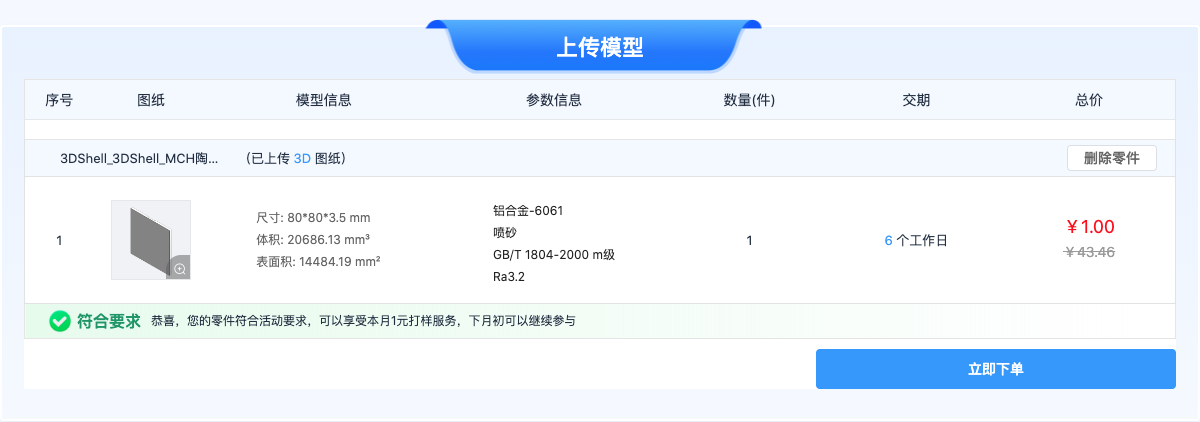
Prototype 2 uses a JLCPCB CNC (one-dollar prototyping) 80mm x 80mm aluminum alloy plate and a 220V 220Ω 70mm x 15mm x 1 MCH ceramic heating element for assembly. The cooling fan is a Yongli MGT6012ZB-W15 (6CM 12V 0.43A), and the simulated load is a 70*50*1.6mm immersion gold PCB board.
As shown in the table above, the measured data of both prototypes basically meet the temperature and speed requirements of each stage of the "ramp-type reflow soldering temperature curve". Subsequent actual soldering tests have yielded very satisfactory results; the quality and speed of soldering surface-mount components are far superior to manual soldering! Most importantly, its functionality, aesthetics, and cost-effectiveness are all very high! Assembly is also extremely simple; beginners can directly replicate it. All materials are completely open source, requiring no activation code, and the entire hardware installation requires no firmware flashing or maintenance. Once installed, it's almost a one-time setup.
BOM List:
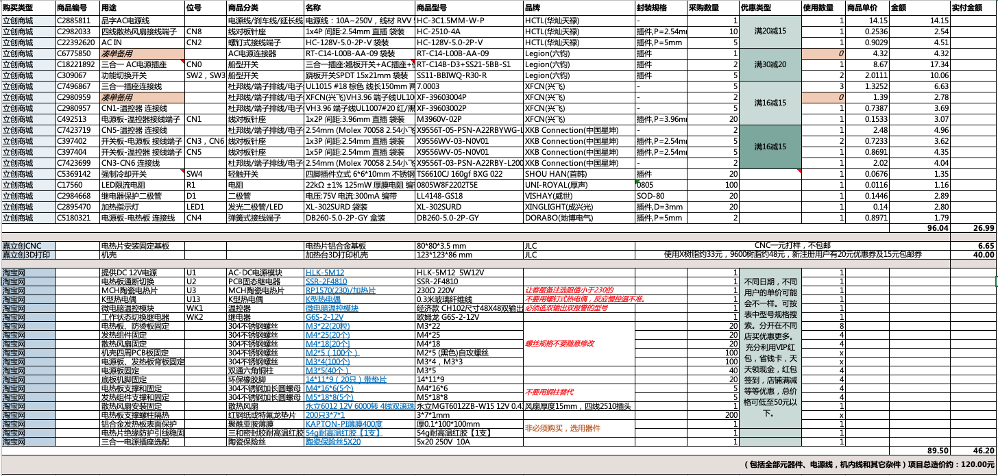
The BOM list shown in the image above is attached as "All Component BOMs". Except for the components recommended to purchase from LCSC Mall, all other components are provided with their uses and relevant purchase links for reference. The models are already selected; simply click to add them directly to your Taobao shopping cart.
For the overall safety, stability, reliability, and durability of the device, it is recommended to purchase some key components from LCSC Mall. Their BOM list is detailed in the attached "LCSC Mall BOM". You can import and confirm the BOM through the "BOM Matching" entry on the LCSC Mall homepage, add it to your cart, claim brand coupons, and then place your order.
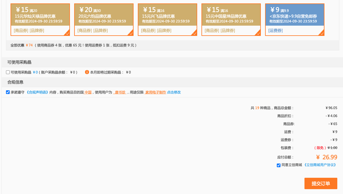
The author has spent considerable time optimizing the components in the LCSC Mall BOM list; currently, after combining items with discounts, the total cost is much cheaper than buying them individually, leaving many components unused. It is recommended that those who need to replicate the device claim the coupons for each brand shown in the image below and place their orders promptly. Since the discount coupons for each brand change frequently, the mall is currently also offering a 9 RMB shipping coupon, which is a great deal! (It is also recommended to prototype the aluminum alloy substrate for LCSC CNC one-yuan prototyping as soon as possible, as the one-yuan prototyping rules may change at any time.)
The physical demonstration shows
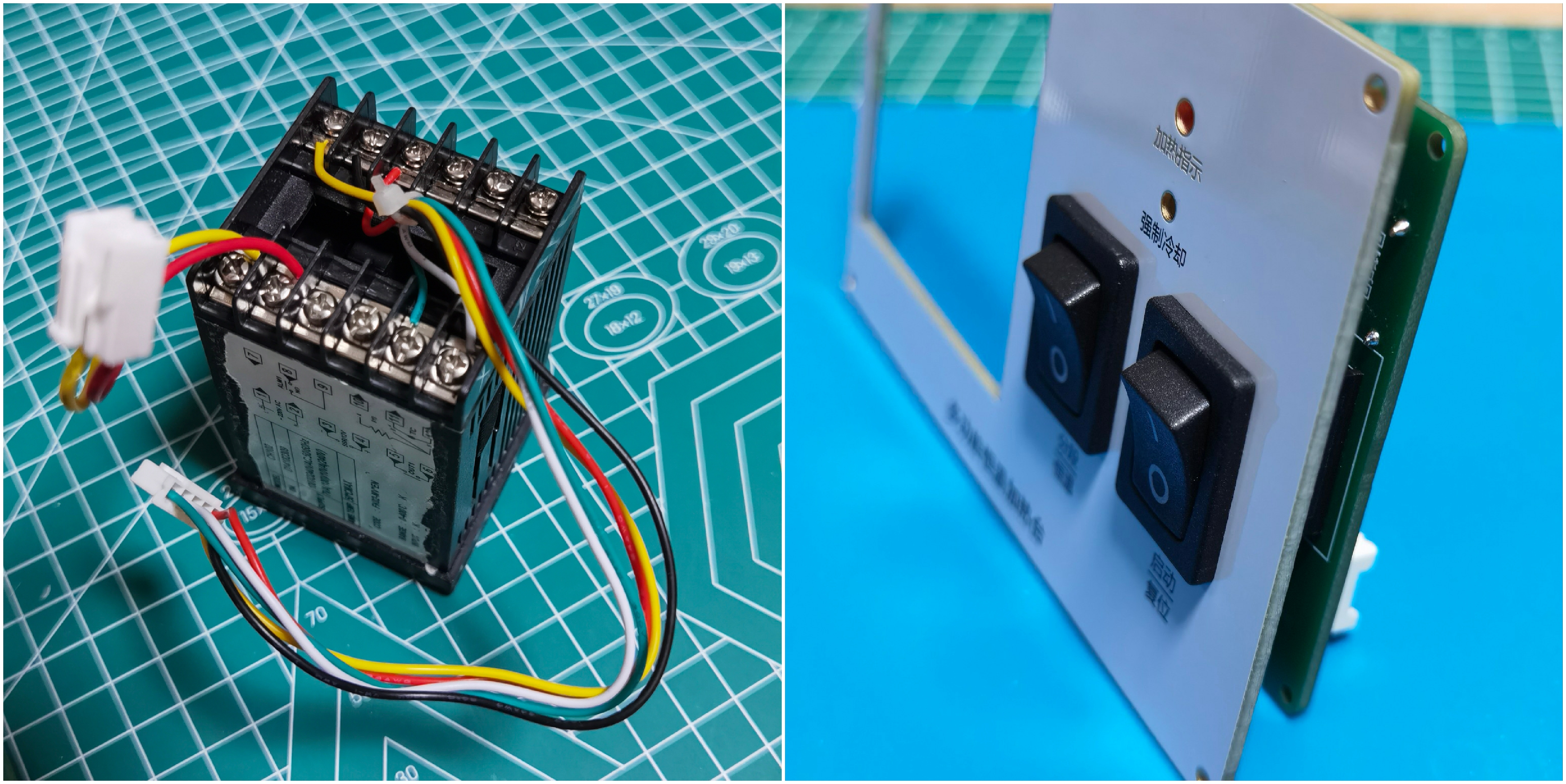
that the entire unit only requires soldering these two simple PCB boards: the switch board and the power board

. For the panel assembly, first assemble the rocker switch onto the panel, then solder the switch board to the rocker switch; no screws are needed for fixing. Then install the two sets
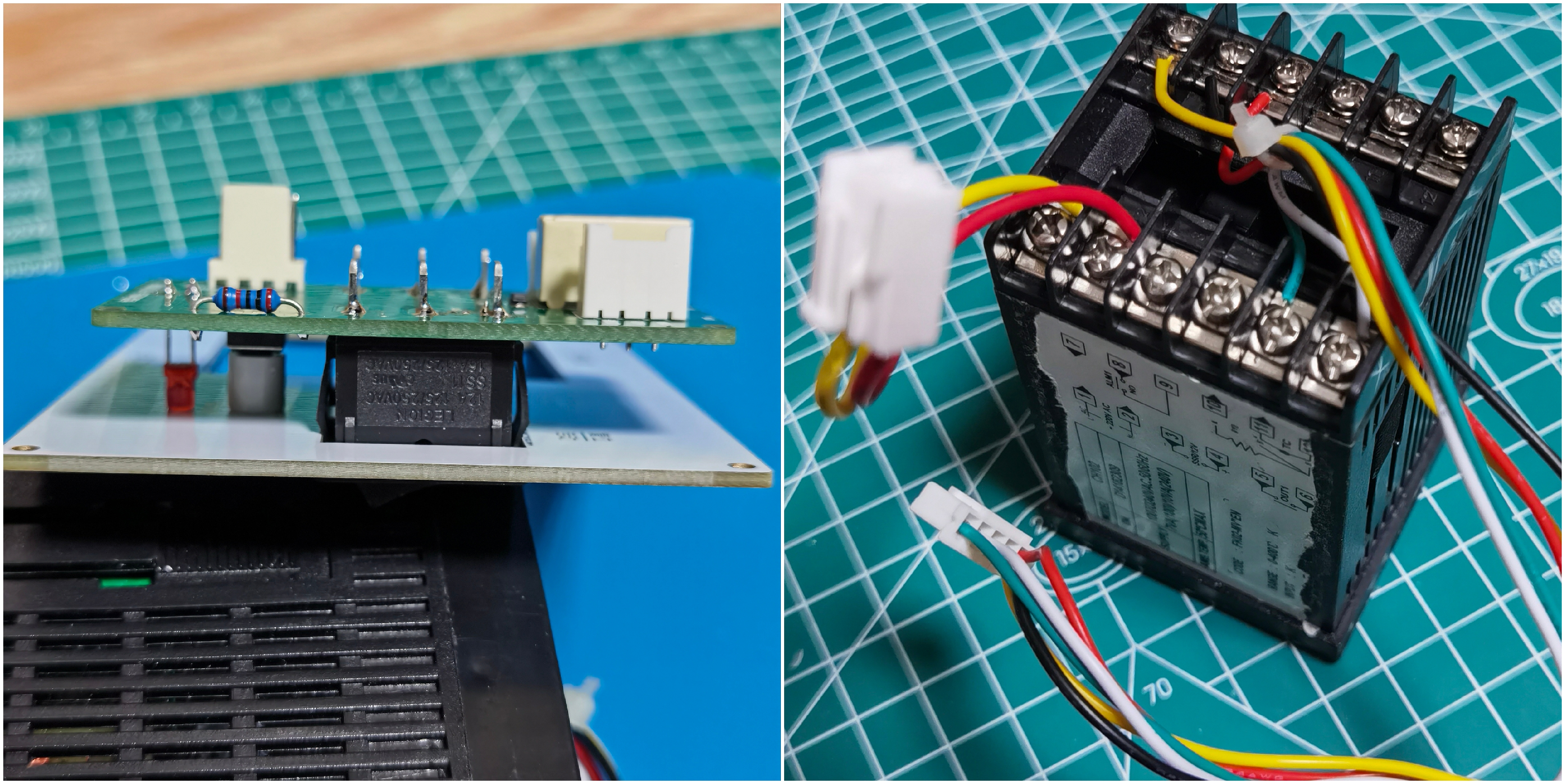
of terminal wires on the thermostat. For the back panel assembly, first fix the power socket and power board to the back panel, and connect the connecting wires between them.

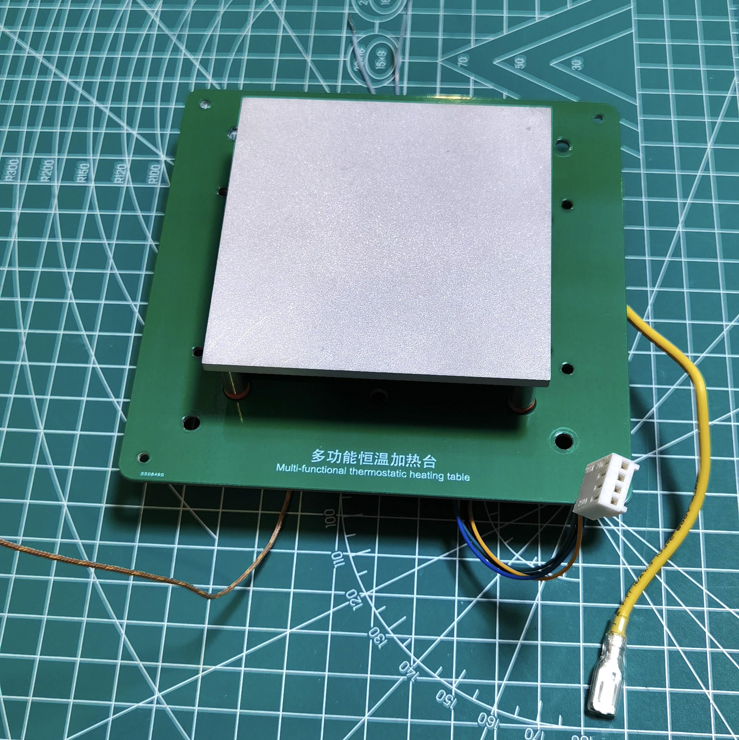
For the heating plate, first tap the aluminum alloy substrate directly with M3 stainless steel screws, then peel off the tape on the ceramic heating element, then seal the two solder points with high-temperature silicone, and finally fix the heating element (if the heating element is not tightly attached and is loose, a 15*0.1mm high-temperature resistant polyimide film can be placed in the mounting groove of the aluminum alloy substrate). Finally, insert the thermocouple probe into the appropriately sized reserved hole, ensuring it is in full contact with the aluminum alloy before fixing it with screws. (The black screws in the picture are M3*3, and the screws for fixing the thermocouples are M3*4.)


Heating Components: Install the heating plate, fan, and grounding wire onto the heat insulation board (the top PCB can also be used as a temporary substitute).

Overall Assembly: Assembly sequence of components: Front panel assembly > Fix the thermostat > Heating component > Back panel assembly > Connect all connecting wires and thermocouple leads > Check for errors and power on for testing > Install the base plate and feet > Install the side panels > Complete

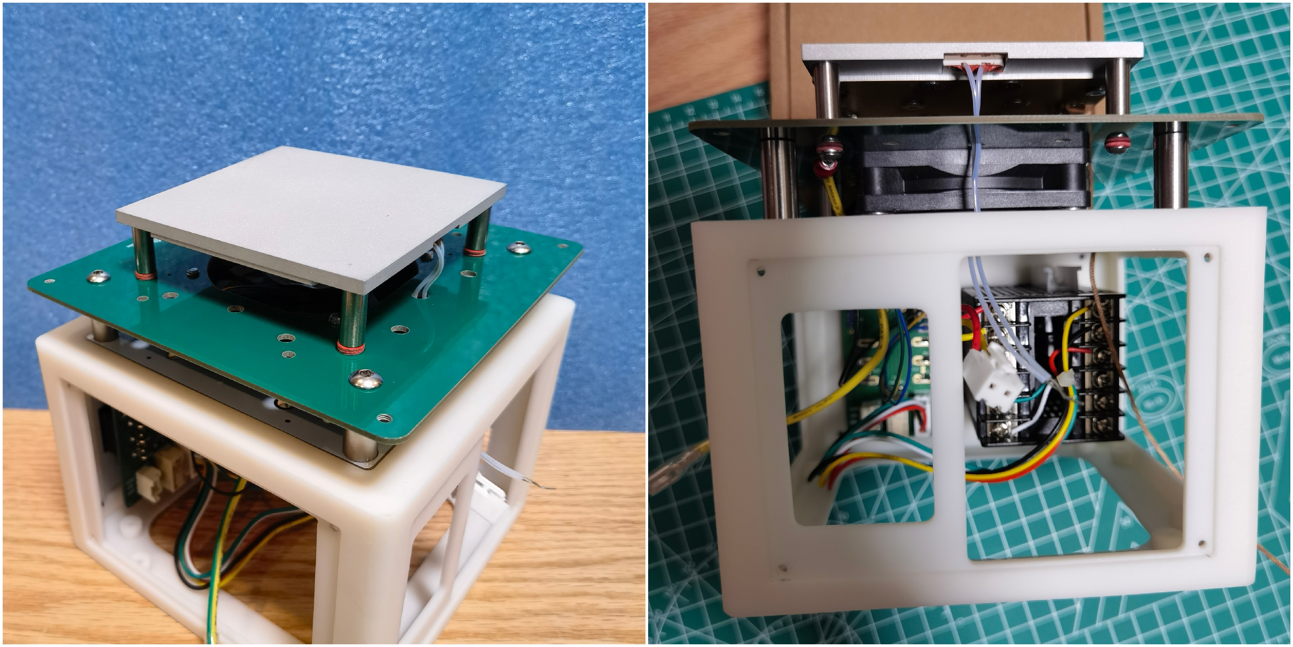


the beautiful appearance. The front and top panels are made with free white gold-plated PCBs, while the side panels are made with colored silkscreened PCBs. If you don't have a coupon, you can have a white PCB made and apply your own stickers; it will still look good.
Anti-scalding Plate: Many people seem to have been burned using homemade heating platforms? Therefore, before using this heating platform, it is strongly recommended to install an anti-scalding plate made from this PCB board. Although I think it slightly lowers the overall aesthetics, it's free and safe. (A total of 12 1.6mm FR4 boards are needed, stacked to a thickness of nearly 20mm. After assembly, it will be slightly lower than the heating plate. The PCB design diagram is also provided in the open-source project.)
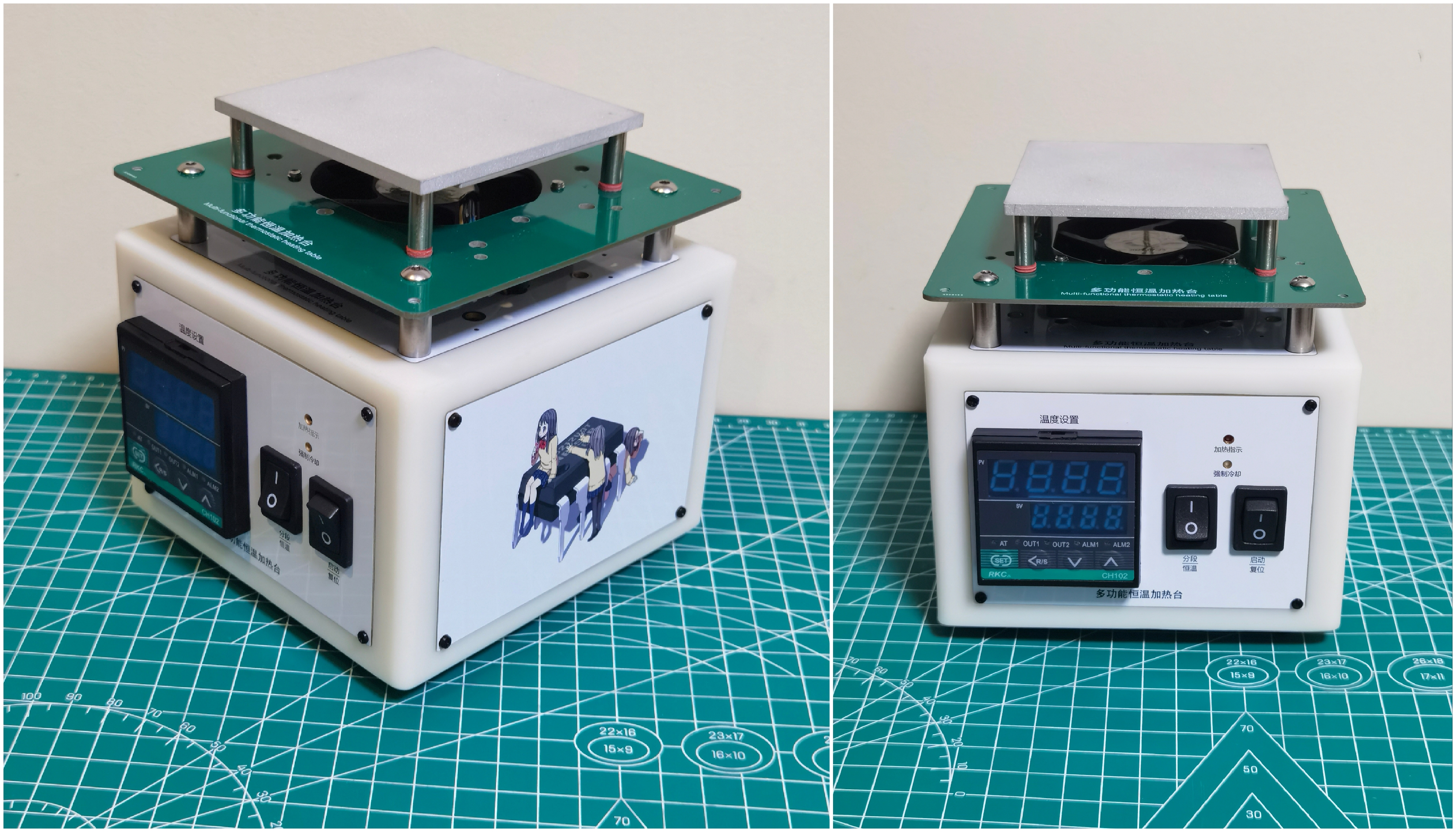
If you're like me and prioritize aesthetics, refer to the first prototype below. You can make a heat shield using bakelite board, and the 3D printer shell can also be painted to your liking.

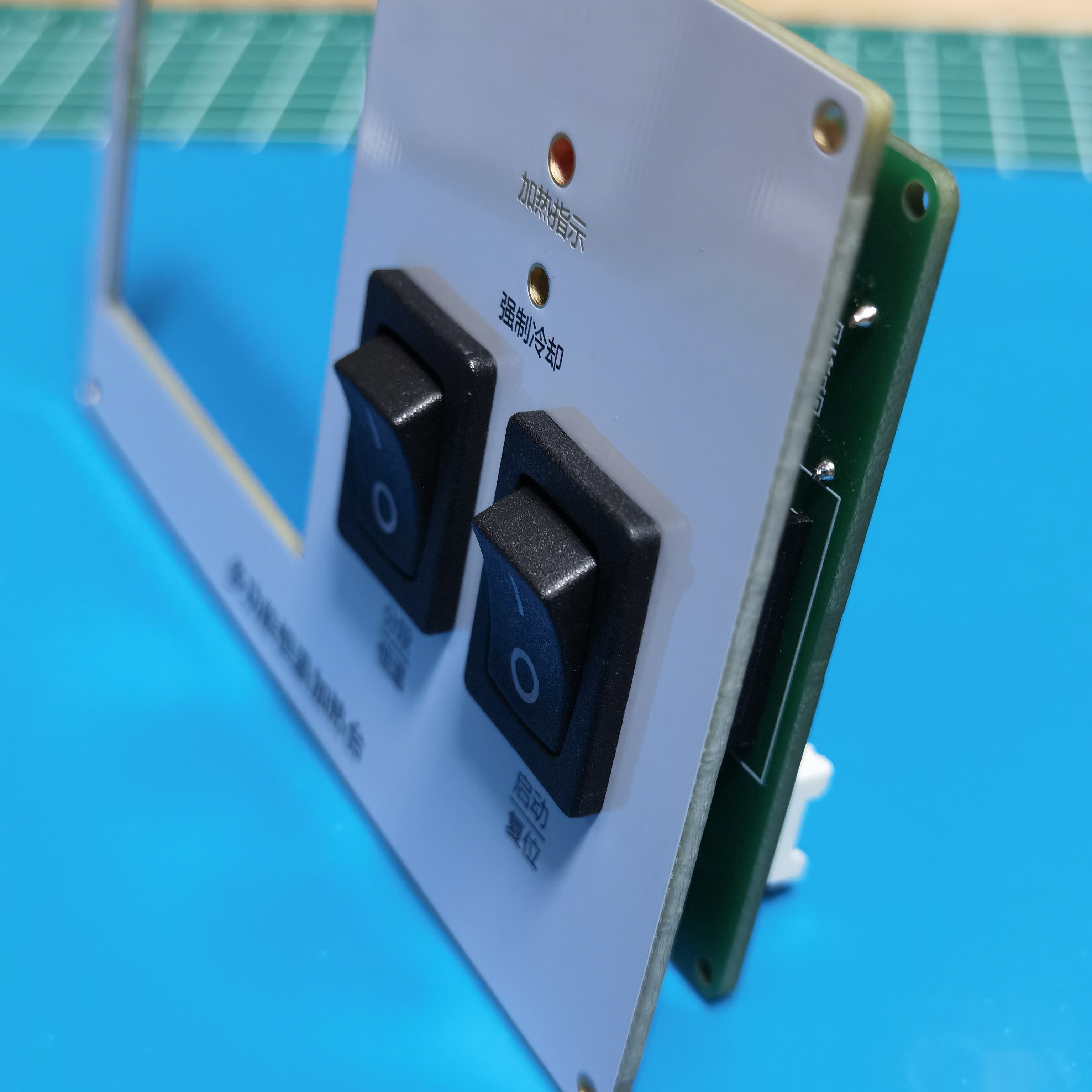
The industrial-style panel is simple and straightforward. The heating plate's working indicator light is the "Heating Indicator" LED on the panel; ignore the LED on the temperature controller.
"Forced Cooling" is a touch switch, allowing users to interrupt heating at any time and start the fan to cool the heating plate. When needed, simply tap it with a marker or toothpick.
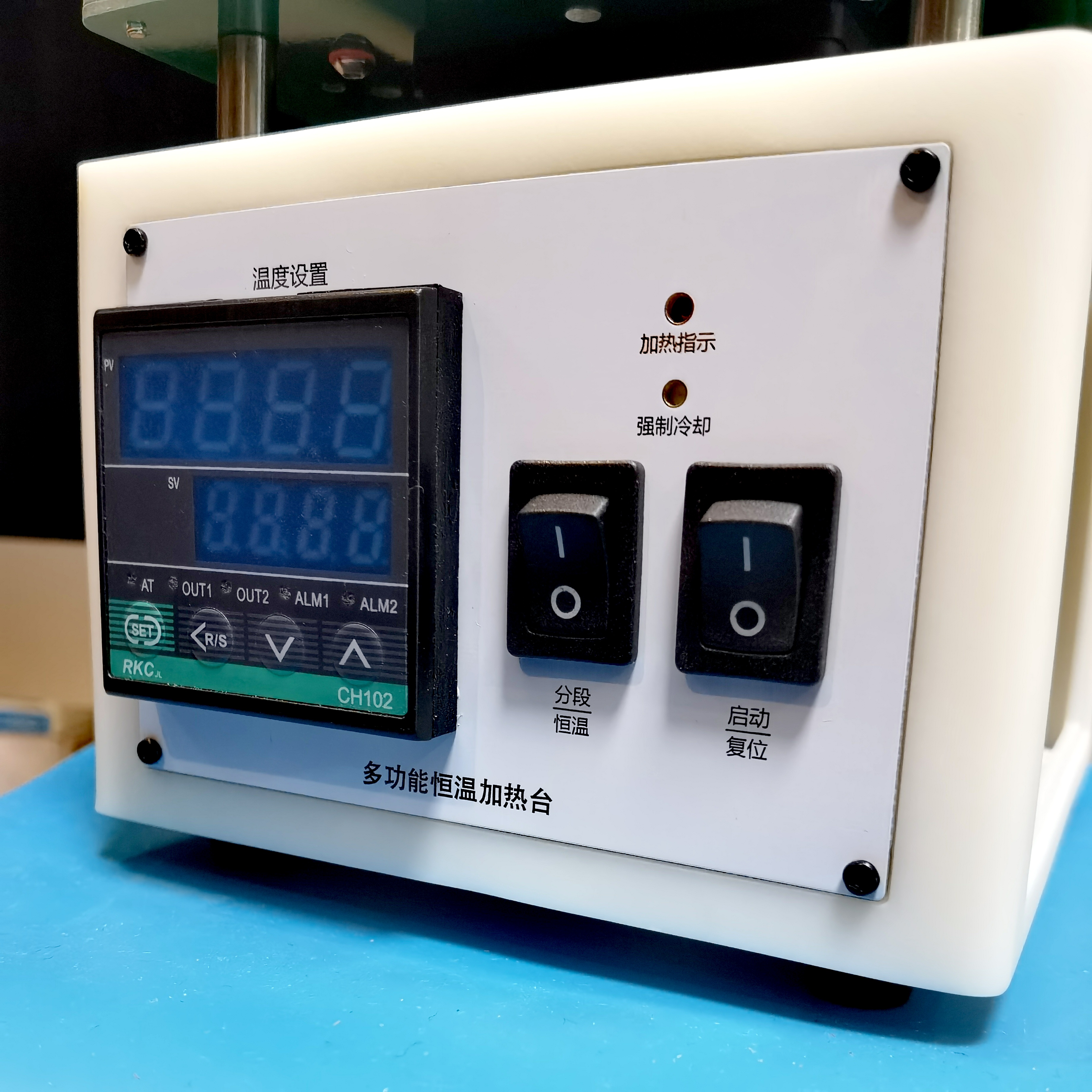
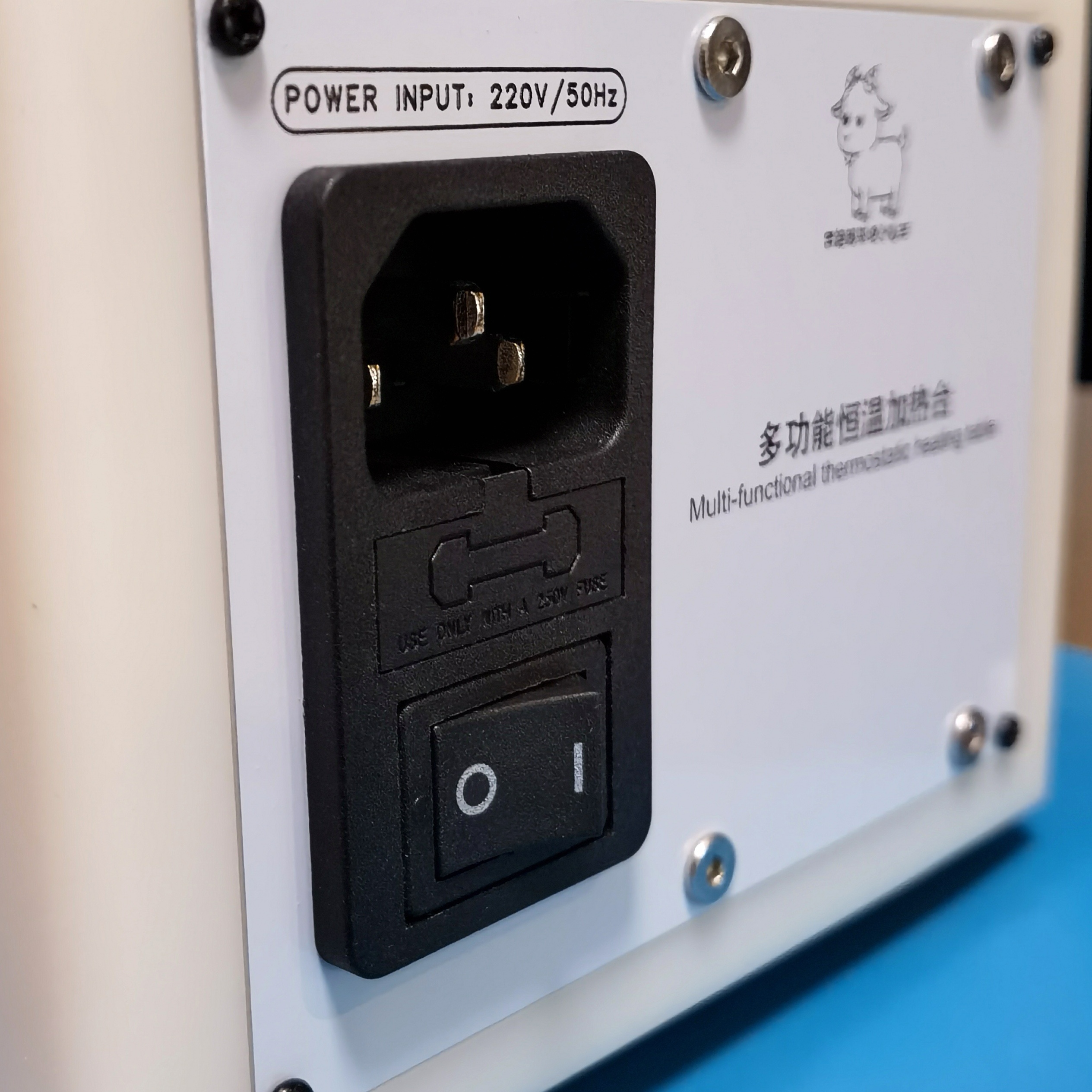
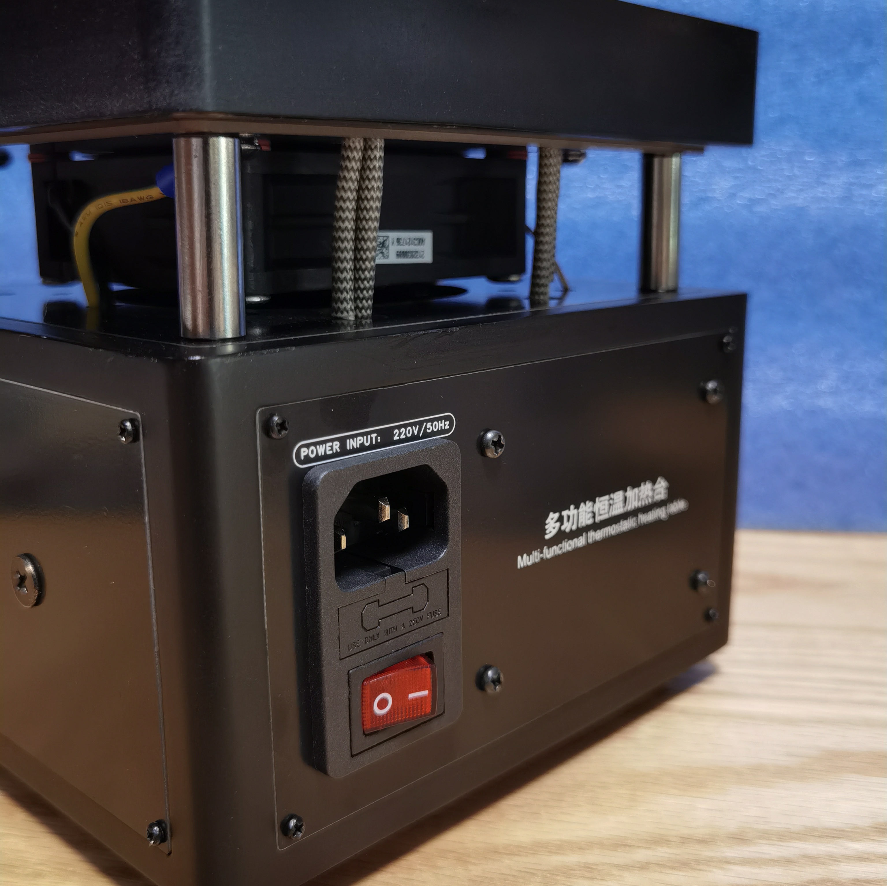
The three-in-one AC socket is of good quality (but a fuse is required). Below is the main power switch for the entire machine.
The temperature display uses a large digital display on the temperature controller, simultaneously showing the "Preset Temperature" and "Measured Temperature," which is simple, clear, and unaffected by ambient light.

Prototype 1: Below is the earliest completed prototype with a timer function. Its circuit diagram is also available in the open-source project. Those who need timed, constant-temperature heating can refer to it for replication.
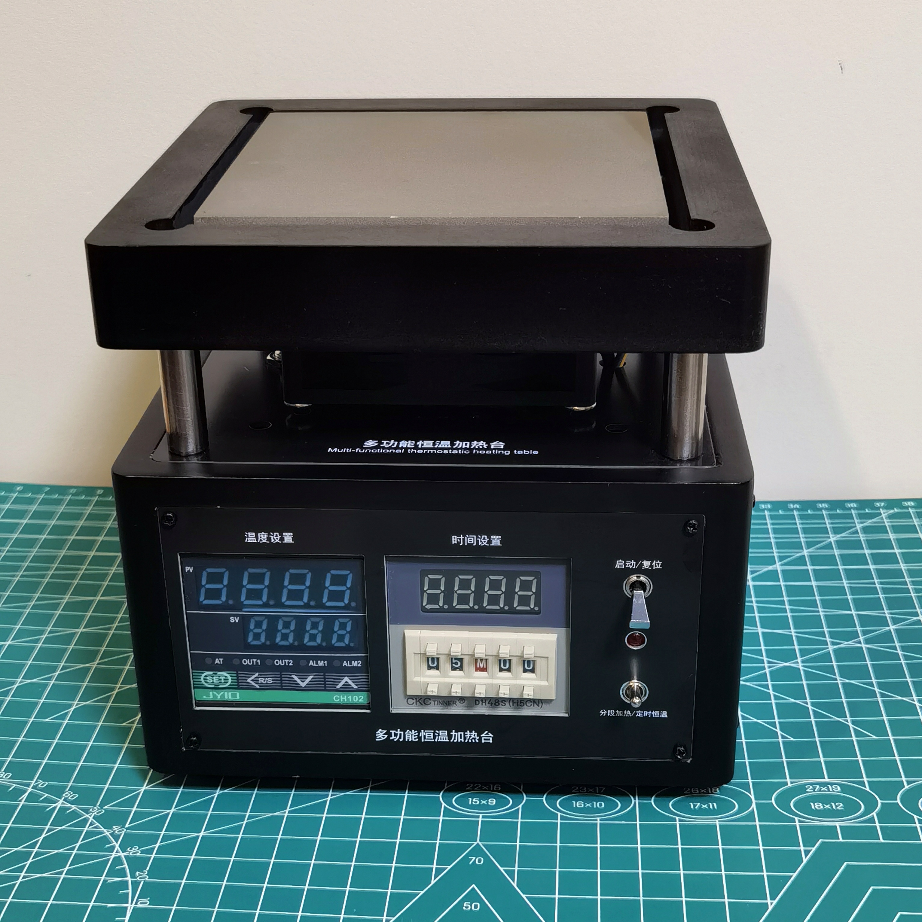
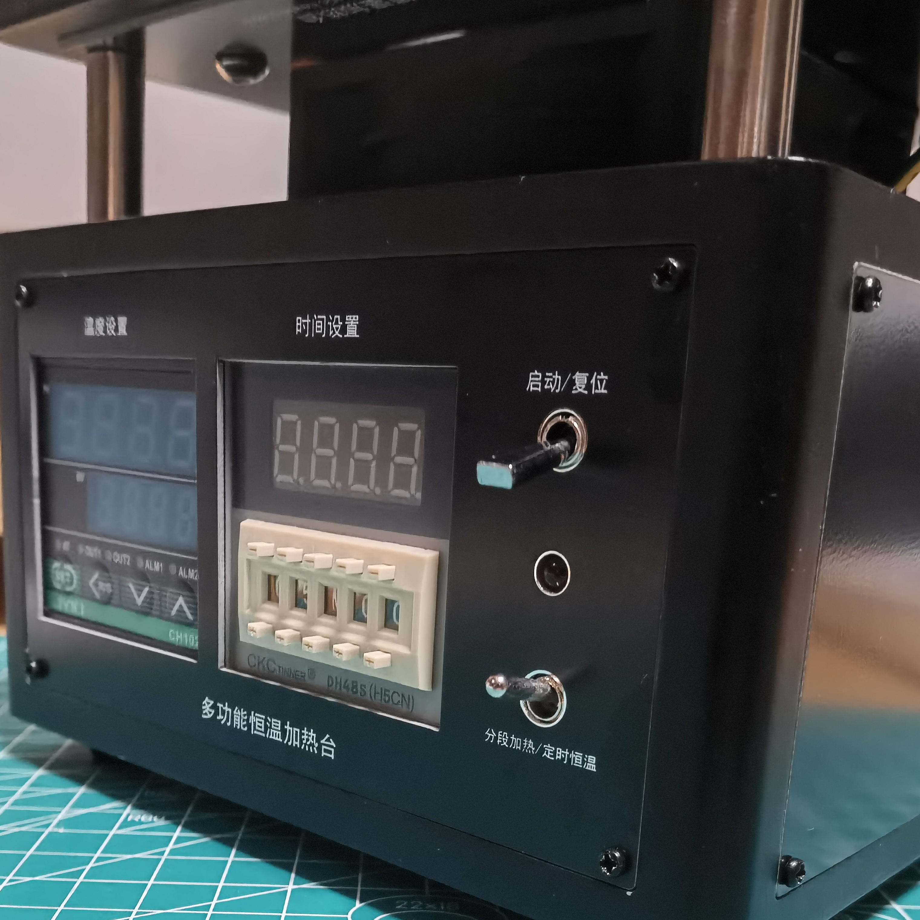
(Group photo
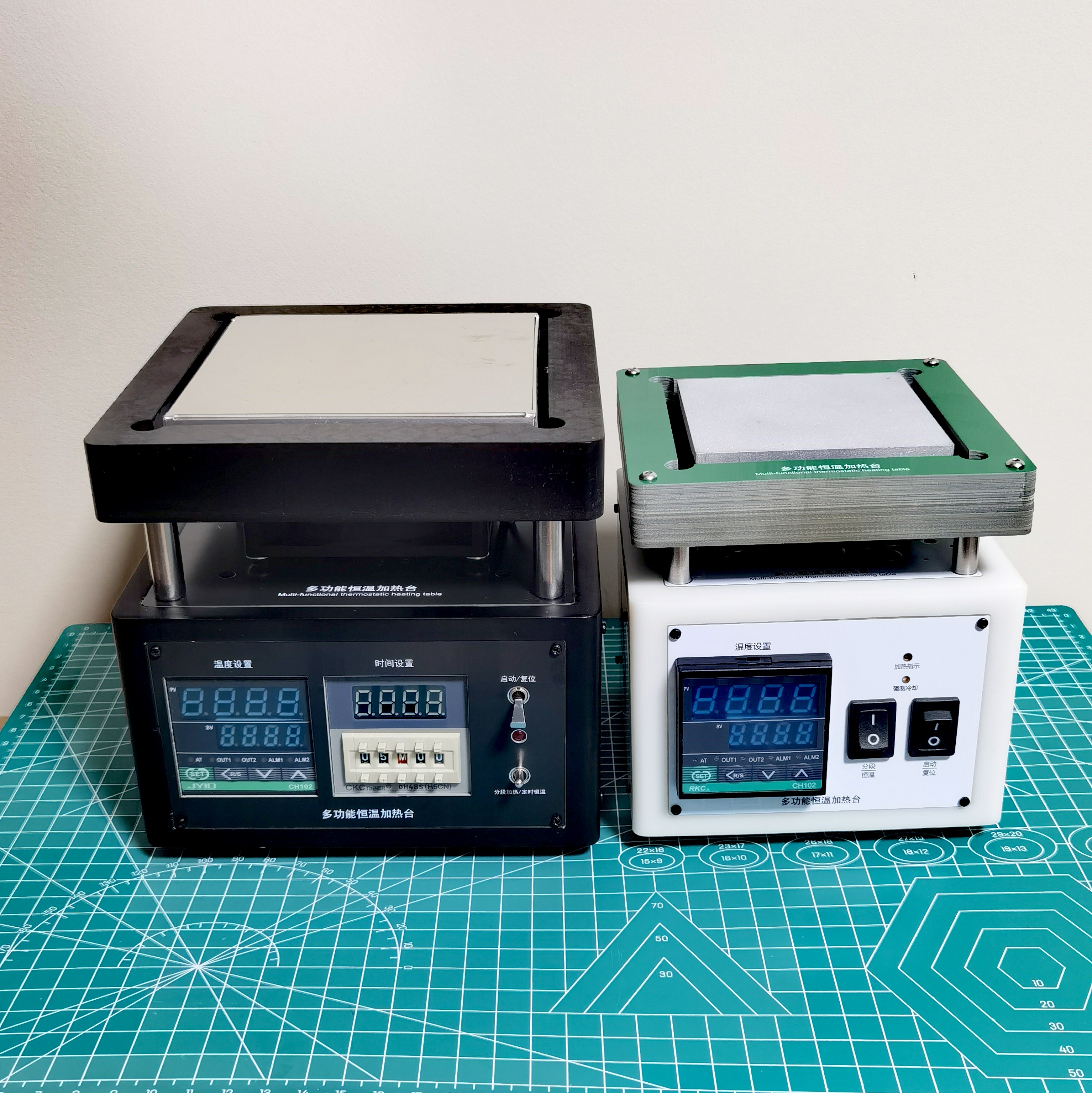
included) Important Notes :
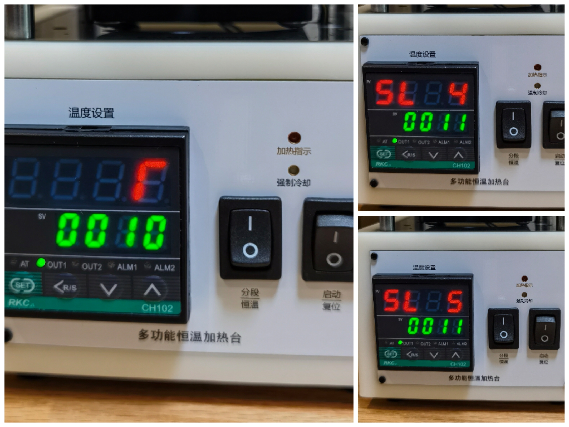
After assembling the entire unit and powering it on without any abnormalities, the temperature controller must be set to achieve the segmented heating function. First, set the start/reset switch to the reset position, then turn on the power switch.
Parameters that need to be set first: (Please refer to the instruction manual for instructions on how to access each parameter setting interface)
Parameter Name Parameter
Description
Setting Value
T
Working Cycle
10
SL4
Process Value Upper Limit Alarm
0011
SL5
Process Value Upper Limit Alarm
0011
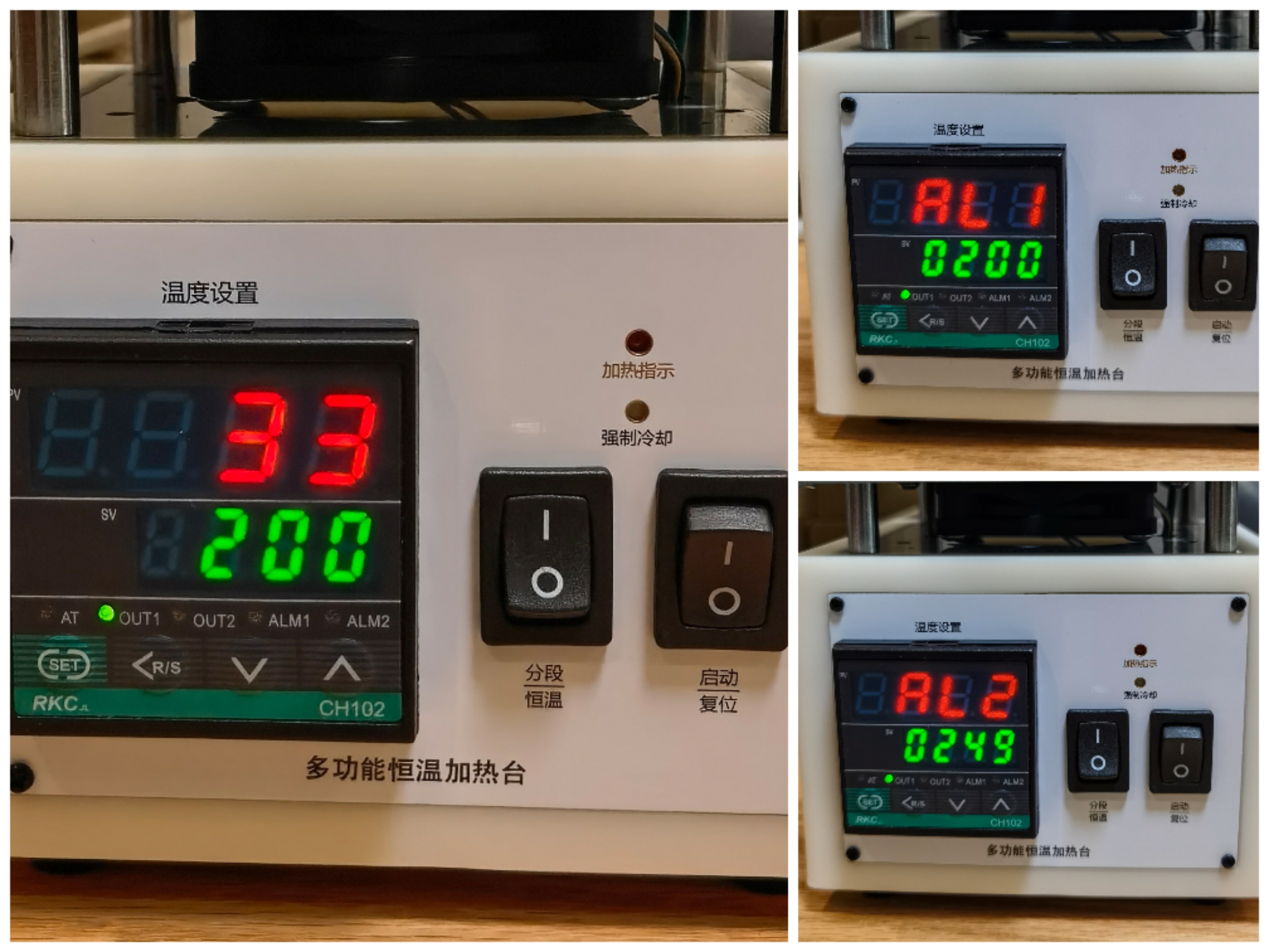
After setting, turn off the power and restart. Then set the following parameters (taking 217ºC medium temperature lead-free solder paste as an example)
Parameter Name
Parameter Description
Heating Platform Setting Description
Setting Value
SV
Preset Temperature ()
Constant Temperature Zone Maximum Temperature
200
AL1
First Alarm Setting
Set to equal to or slightly lower than the value of SV, exit PID control
200
AL2
Second Alarm Setting
Return Flow Zone Peak Temperature
250
Finally, set the ATU self-tuning to 0001, and then press and hold the temperature controller "SET" button to exit the setting mode.
First, set the heating platform "Mode Switch" to the constant temperature position, and then turn on the start switch. At this time, the temperature controller will automatically perform PID self-tuning. Wait patiently until the AT light stops flashing, and the temperature should be constant at around 200ºC. Pressing the "Forced Cooling" switch should immediately turn on the fan to cool the device down until the temperature drops below 50ºC, at which point it will shut down. The parameter settings are now complete.
Then you can conduct data testing or trials. Using solder paste with different melting points only requires adjusting parameters SV AL1 and AL2. For reflow soldering temperature settings, please refer to relevant online articles; different solders require different temperature settings.
When
I first participated in the Spark Program, I built a prototype. At that time, thanks to the various benefits of the Spark Program, I luxuriously used a custom CNC aluminum alloy heating plate, a black painted 3D printer casing, a large PCB, and most of the components were provided free of charge by LCSC. JLCSC's FA department even provided a set of screwdrivers. However, after completing the project and calculating the total cost, I realized that replicating that solution would be too expensive.
My initial motivation for participating in the Spark Program was to design a heating platform solution that beginners could easily replicate at low cost. The author then spent considerable time redesigning the new system, omitting the rarely used timed temperature control function, replacing the heating plate with an 80*80mm aluminum alloy plate (no customization required, JLCPCB CNC prototyping available for a small fee), and reducing the PCB size to a level suitable for free prototyping. Simultaneously, the reduced overall size significantly lowered the cost of the 3D printed casing. The author also made multiple modifications and optimizations to the components used, ensuring that most components were eligible for discounts. After final calculations, the total cost of replicating this project was only a little over one hundred yuan, a pleasant surprise and a testament to the initial goal. The attached
welding test video
provides a complete set of documents for this project, including circuit schematics, PCB design drawings, 3D printing, and CNC aluminum alloy substrate (including the circuit schematic for prototype one), all of which are completely open source.
The 3D printer casing has a frame structure, and using PCBs on all six sides significantly reduces 3D printing costs (since PCBs can be prototyped for free). Installation is also particularly convenient, and most importantly, text and patterns can be silkscreened!
The attached CNC aluminum alloy substrate measures 80mm*80mm, features a fixed bottom design, a smooth and flat heating panel, and a heating plate power of approximately 130W-220W, sufficient for most SMT needs of amateur enthusiasts.
Those interested in this project can join QQ group 994639947 to exchange ideas and share experiences. If you find the project helpful, please give it a thumbs up to encourage me!
Thanks to the various business departments of JLCPCB for providing various free support for the project, and special thanks to Mr. Chen, the contact person for the JLCPCB Spark Program, for his patient coordination and guidance!


 京公网安备 11010802033920号

 LOP380-P


