Video Link:
[Link Above]
The uploader is a bit lazy, please wait a moment while it's finished...
Project Introduction:
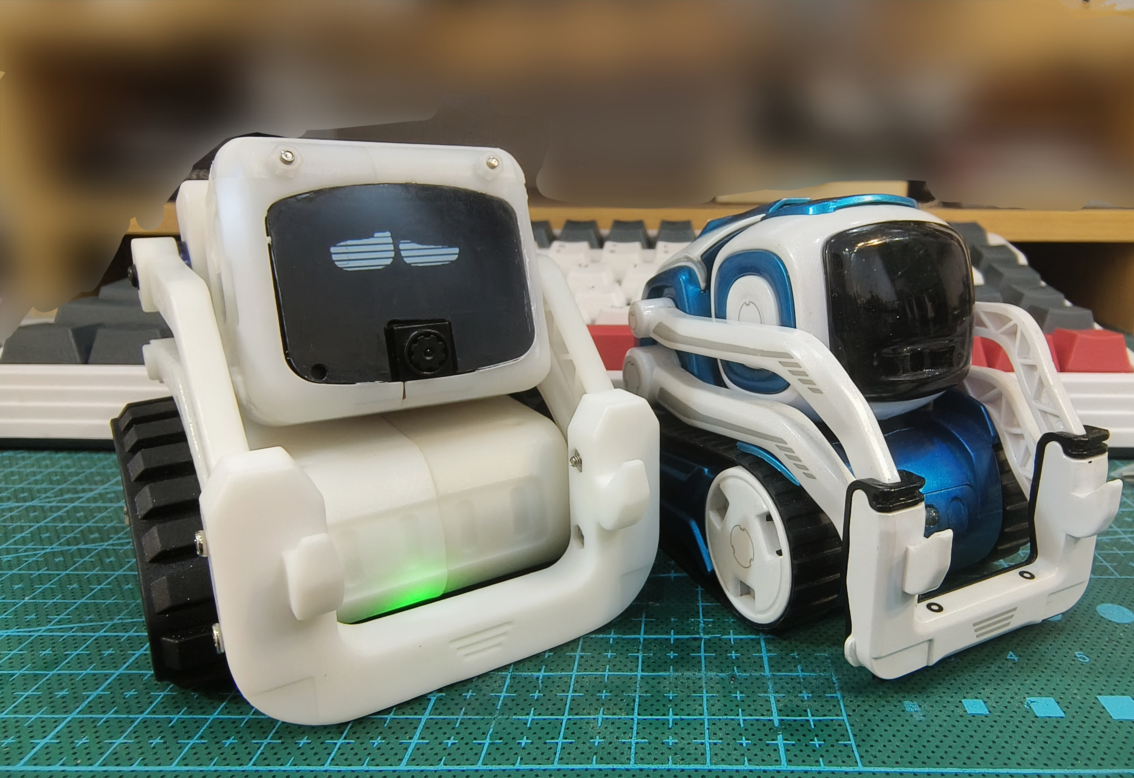
This project is a desktop interactive robot. The design is inspired by Anki's Cozmo robot, featuring 3 degrees of freedom (2 arms, 1 head). It uses custom-modified servos to support joint angle feedback. Human-computer interaction is possible via voice wake-up and recognition using an ESP32 microcontroller.
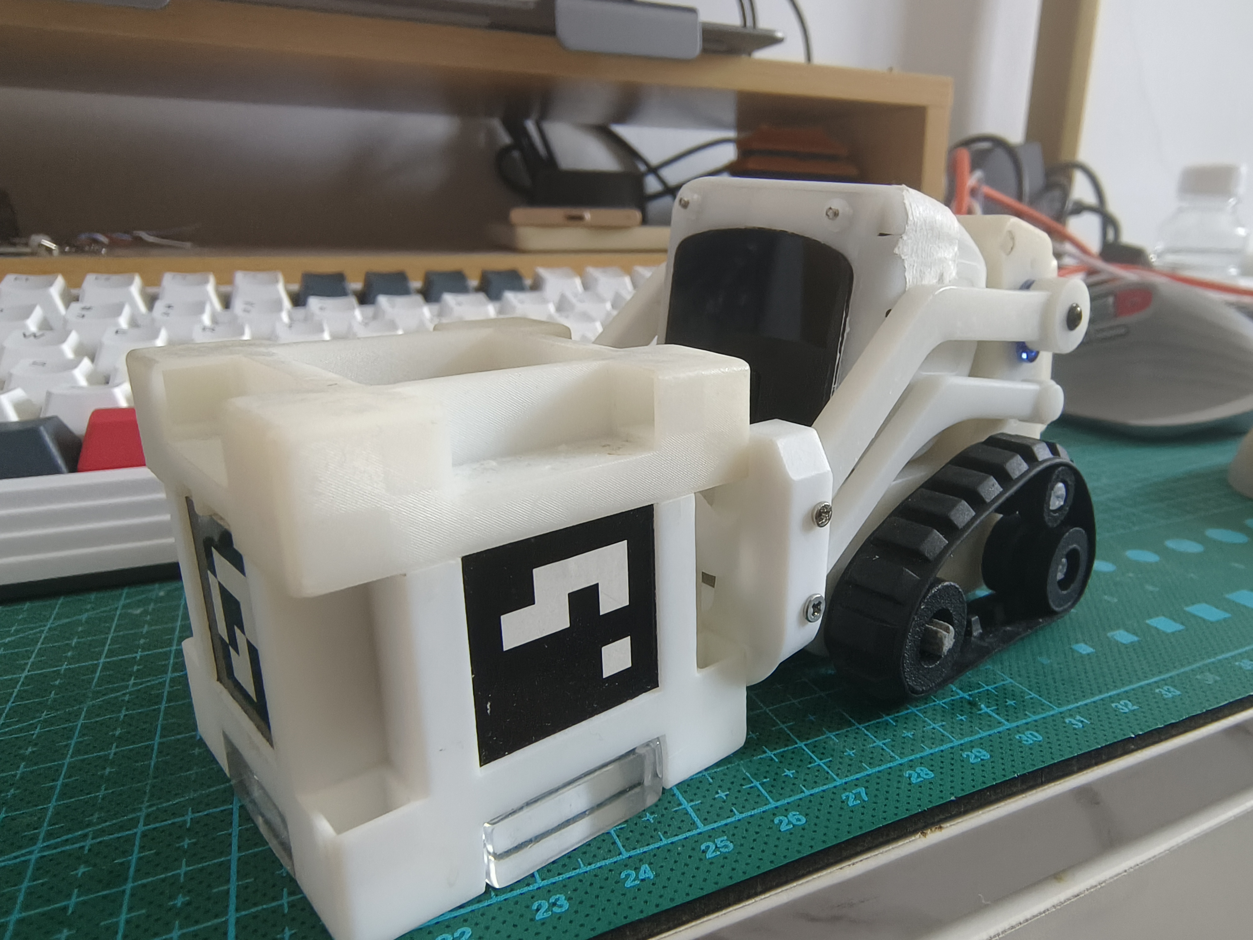
The entire project consists of the following parts: robot chassis + robot head + interactive cube.
Like this project? Please consider giving it a Star ⭐️ to help improve it!
Any questions/bugs are welcome and feedback is welcome.
The project's
main functions are as follows:
mobile phone remote control RC;
LAN image transmission;
voice interaction;
Rubik's Cube and robot interaction.
Project parameters
: The robot mainly consists of two parts: head and chassis.
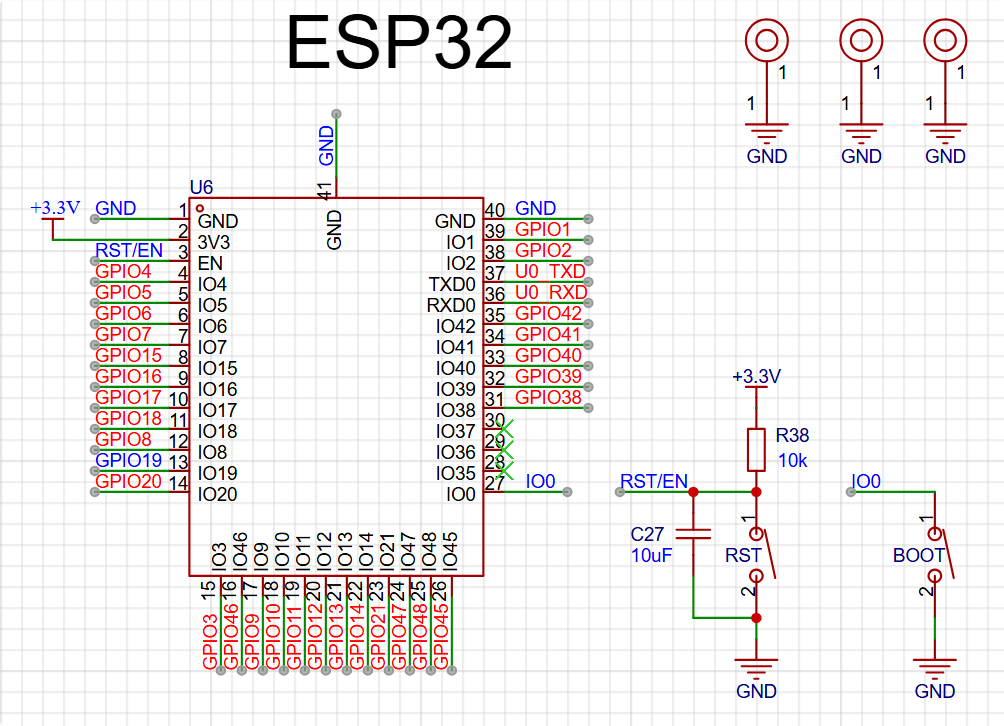
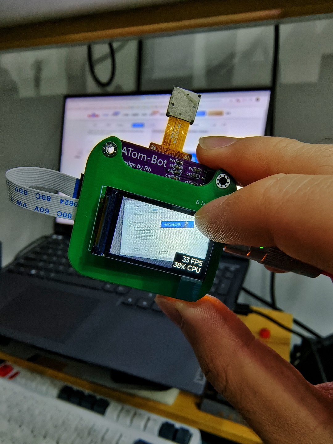
The head uses an ESP32-S3 main controller as the "brain" for UI interaction, network communication, and lightweight AI processing.
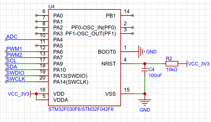
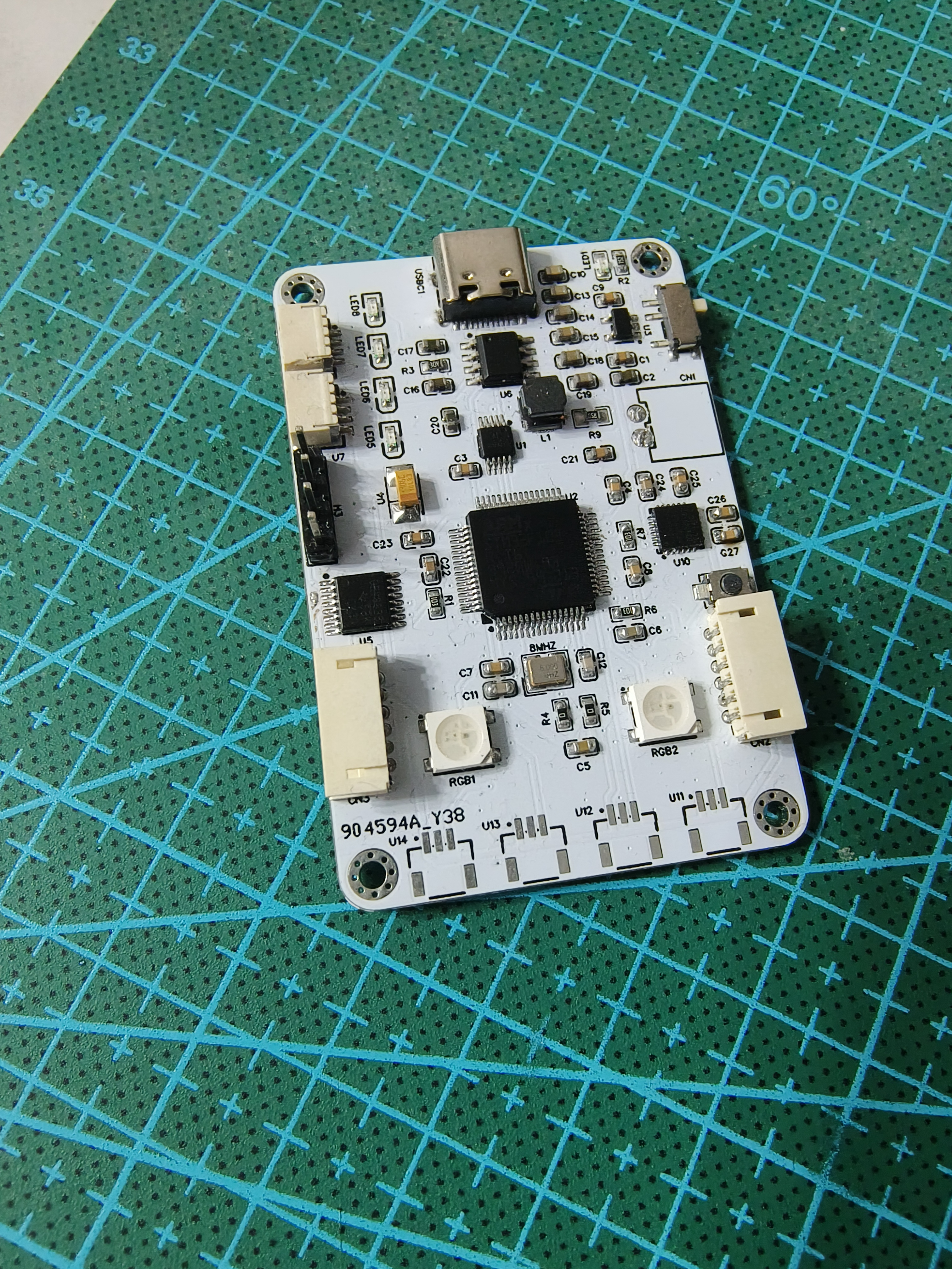
The chassis uses an STM32F103 main controller as the "cerebellum" for motion control.
The Rubik's Cube uses an ESP32-S3 main controller.
Principle analysis (hardware description)
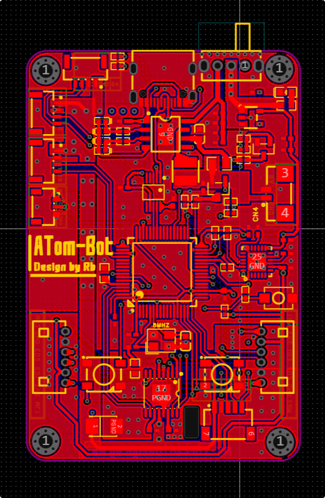
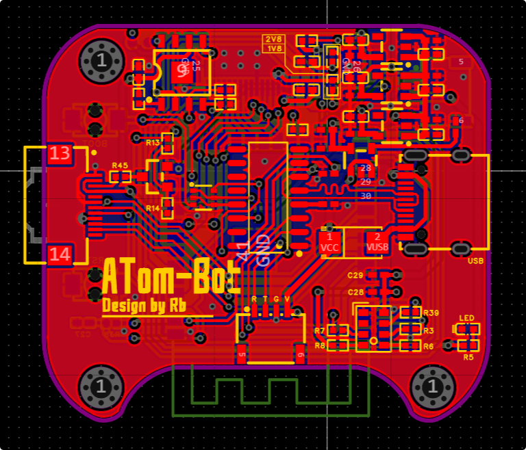
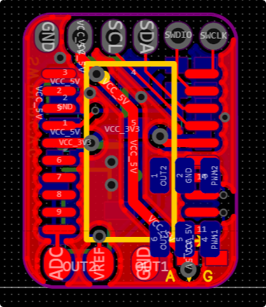
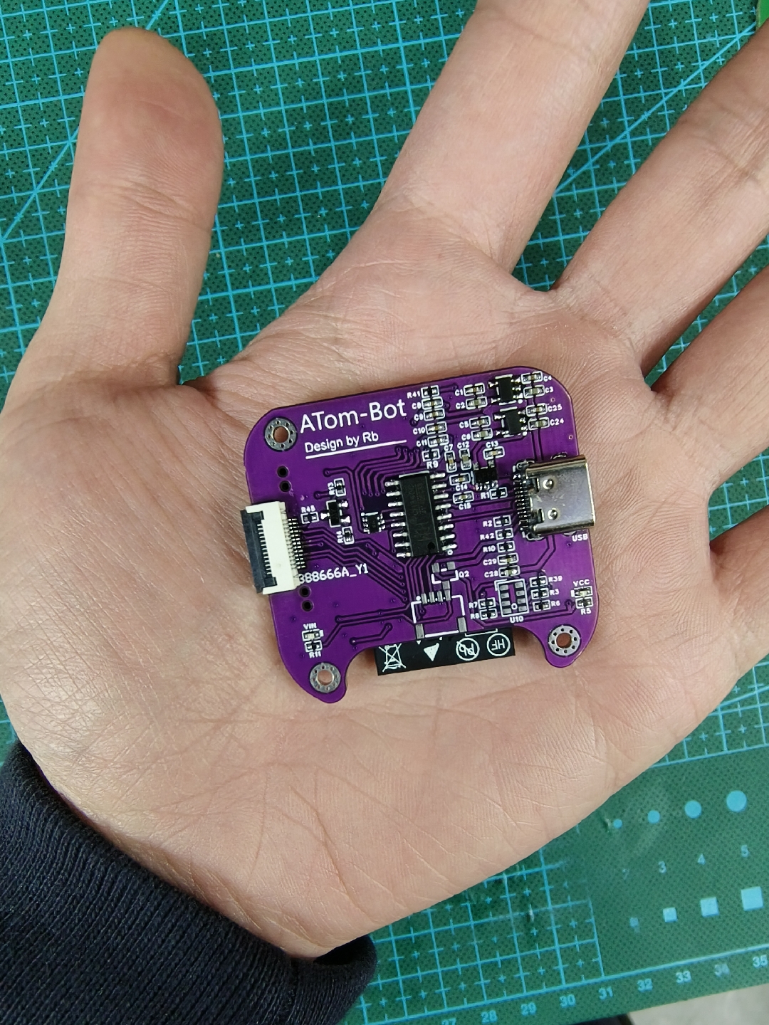
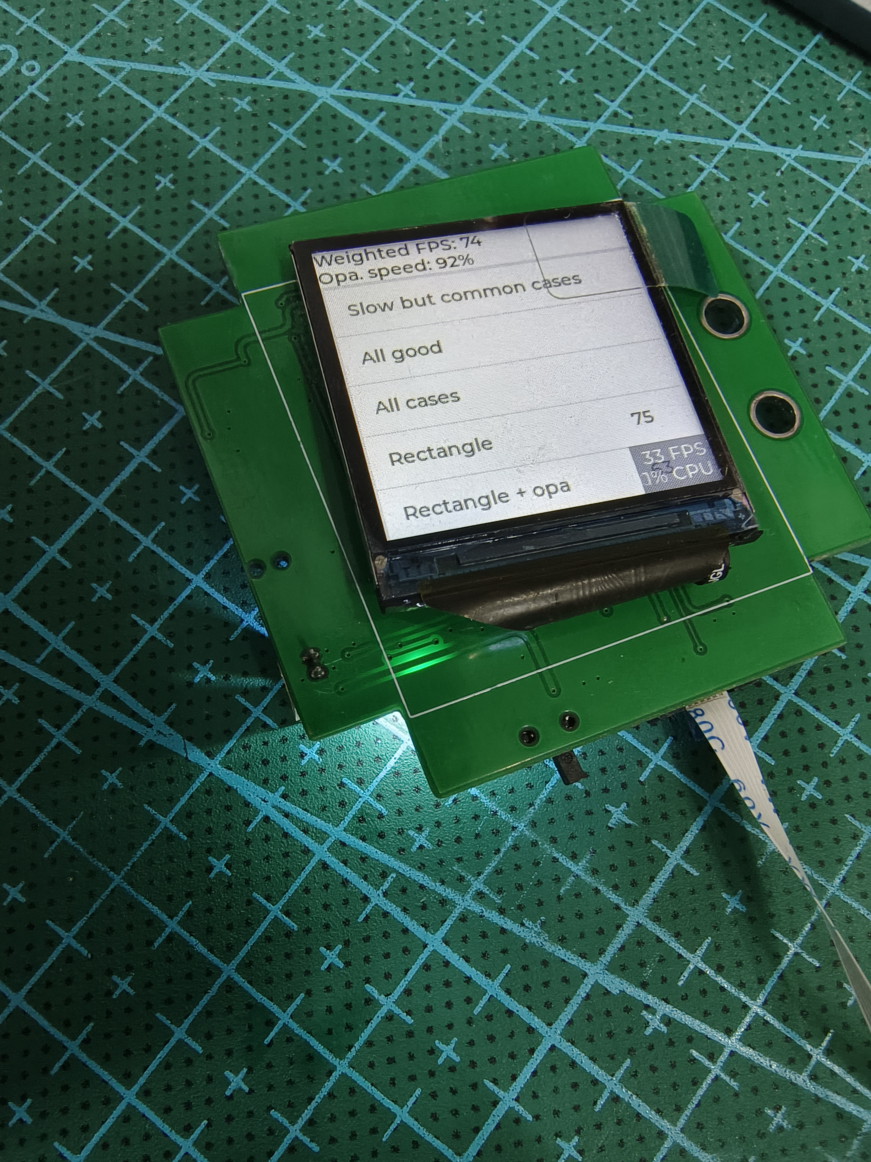
: The robot body has a total of 6 PCBs, including: chassis + servo control board x3, head base board + head LCD expansion board.
Chassis design:
The robot's chassis needs to meet the following basic functions:
support one serial port MSH interaction (those who have used rtthread know how great it is),
communication with the head development board (serial port),
support for serial port OTA firmware upgrades
, support for laser ranging and real-time drop detection,
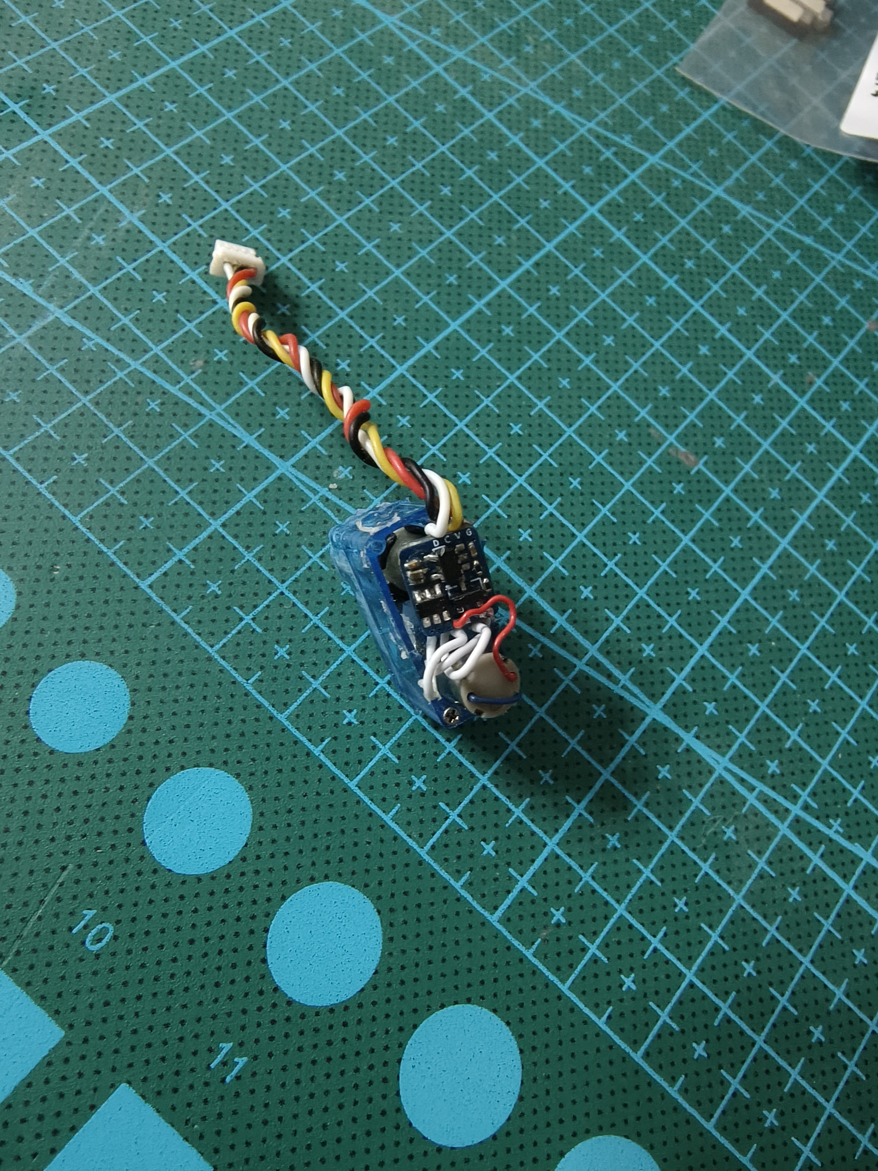
control of two I2C bus servos,
and status display via WS2812 LED strip.
ADC Voltage acquisition and measurement
control of two motors + encoder counting
can detect the robot's status (picked up, shaken, etc.).
Therefore, the following hardware requirements arise:
at least 2 serial ports
, at least 2 I2C buses,
SPI/PWM driver for WS2812
, 1 ADC,
2 hardware encoder interfaces, and
4 PWM outputs.
Therefore, the chassis uses an STM32F103RCT6 main controller
for the following reasons:
1. The price is acceptable;
2. ST's chips have high maturity (mainly software);
3. Resources meet the project requirements with minimal redundancy. The robot's

head design needs to meet the following basic functions: support 1 serial port (MSH) for communication with the chassis (serial port) ; drive one I2C bus; the servo's computing power cannot be too weak (speech recognition and other algorithms need to be deployed); support wireless protocols (remote control, image transmission); support a camera; DCMI interface ; smooth UI animation display ; and audio playback (I2S/DAC). Therefore, the following hardware requirements arise: at least 2 serial ports , at least 2 I2C buses ; built-in wireless RF function ; and support for DCMI/MIPI-CSI. The interfaces need to support high-speed SPI/RGB/MIPI-DSI and I2S/high-resolution DAC interfaces. Therefore, the chassis uses the ESP32-S3 as the main controller for the following reasons: 1. Reasonable price; 2. Espressif's software maturity is relatively high (ESP-IDF); 3. Strong computing power and relatively complete AI edge-side algorithm support; 4. Built-in Wi-Fi protocol stack, bandwidth meets application requirements; 5. Supports DCMI interface for image transmission. The control board design for the robot's arm and head needs to meet the following basic functions: It should function as an I2C slave, with the master controlling the slave's servo motors via I2C. Controlling the servo motors requires force feedback and precise control of servo motor movement. Therefore, the following hardware requirements arise: support for hardware I2C slave protocol ; support for at least two PWM channels; and support for ADC sampling. Therefore, the chassis uses the STM32F030F6 as the main controller for the following reasons: 1. Reasonable price and sufficient resources; 2. ST's chip maturity is relatively high (mainly software). 3. Resources meet the project requirements with minimal redundancy; Material preparation instructions (PCB, SMT + panel printing + 3D shell order): https://docs.qq.com/doc/DY0lzSENnbE1SdGRn Official software code organization ATom-Robot: https://github.com/ATom-Robot Android SDK source code: https://github.com/ATom-Robot/Android Robot firmware source code + 3D files: https://github.com/ATom-Robot/ATom-Bot Software usage instructions Robot chassis instructions Online chassis instructions: https://docs.qq.com/doc/DY0NOTWp4Wk1rdlRy Robot head instructions Online head instructions: https://docs.qq.com/doc/DY05KSXNtQ2pnWlF3 Assembly process Physical images PCB parts have been verified and completed Robot head PCB preview:


Robot baseboard PCB preview:
Robot arm servo PCB preview:
Robot Rubik's Cube PCB preview:
A final
note: This project is for personal use only and commercial use is prohibited
. Finally, because this project is completely open source, if you are interested in the ATom-Bot project, please feel free to contribute your PR!
Below is the official technical exchange group:

3D_Model.7z
Are you dizzy or not? (Just asking you.mp4)
PDF_【Fully Open Source】ATom-Bot Desktop Robot.zip
Altium_【Fully Open Source】ATom-Bot Desktop Robot.zip
PADS_【Fully Open Source】ATom-Bot Desktop Robot.zip
BOM_【Fully Open Source】ATom-Bot Desktop Robot.xlsx
90649
MP4560-DCDC Module
MP4560 - Wide Voltage DC-DC Step-Down Module
This project introduces
the MP4560-DCDC module design, which uses a 6-pin Type-C interface and a 2.543-pin header for input, and screw terminals and a 2.543-pin header for output. The power module has a maximum input voltage of 55V, a fixed output of 3.3V, and a maximum output current of 2A.
Chip characteristics include:
wide input voltage range of 3.8V to 55V;
250mR internal power MOSFET;
programmable switching frequency up to 2MHz;
140uA quiescent current;
internal soft-start
; and adjustable output from 0.8V to 52V.
The circuit
uses a 4.7uf + 100nf capacitor for input filtering; note the capacitor's voltage rating.
The EN pin is floating and enabled by default. If using a voltage divider resistor for enabling, ensure the EN pin's voltage rating does not exceed 5V.
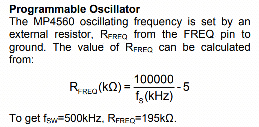
The switching frequency can be programmed via the FREQ pin resistor.
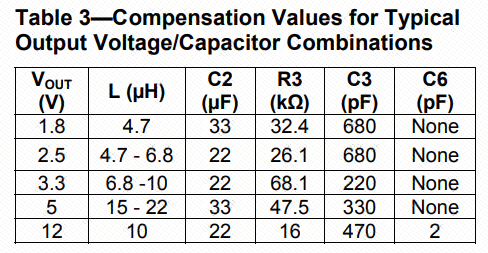
Loop compensation is implemented via the COMP pin for better conversion efficiency.
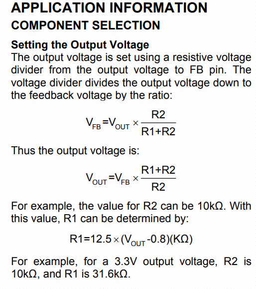
The output voltage is obtained via the FB feedback pin resistor. To modify the output voltage, change the feedback resistor ratio.
Important notes:
When the entire power supply system operates at 5V or lower, it is recommended to add a diode at the BST pin for higher efficiency.
When selecting components, ensure the maximum voltage rating of external components matches the input voltage.
When selecting voltage divider resistors, accuracy should not be lower than 1%, and feedback lines should be carefully considered during PCB layout. When
selecting output capacitors and diodes, pay attention to their rated current values; they should not be less than or close to the actual output current, otherwise, severe overheating may occur.
PCB layout should ideally follow the datasheet. Input and output GND should ideally be on a single copper trace. Note that power supply isn't limited to VIN and 3.3V; any output from a chip pin is considered power.
Widen the copper trace at power supply locations; for 2A current, at least 50mil is generally recommended. Detailed calculations can be made based on the specific application. Adding
silkscreen to interfaces is recommended to prevent future operational difficulties.
PDF_MP4560-DCDC module.zip
Altium_MP4560-DCDC module.zip
PADS_MP4560-DCDC module.zip
BOM_MP4560-DCDC module.xlsx
90650
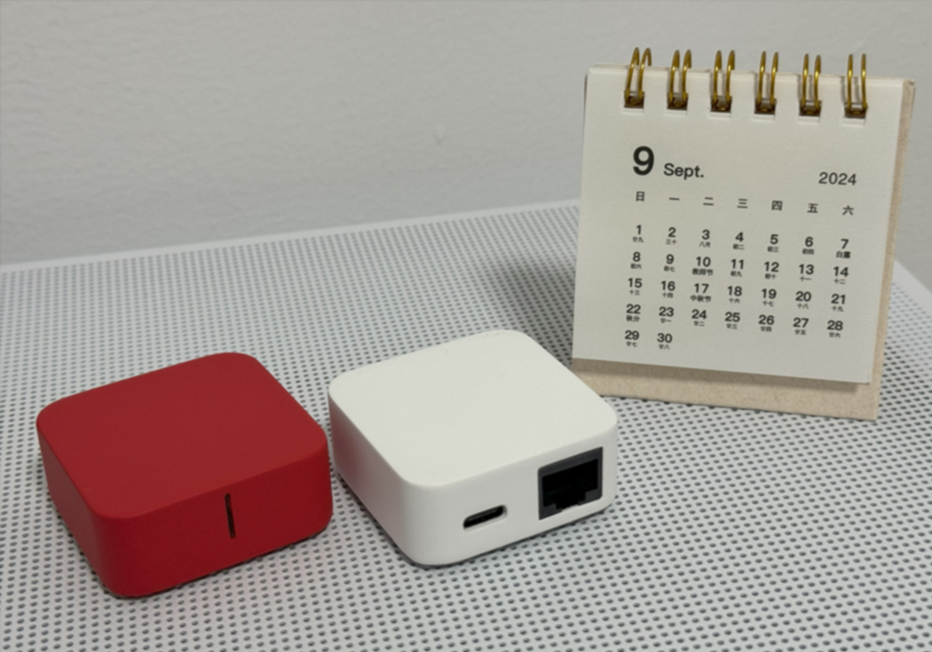
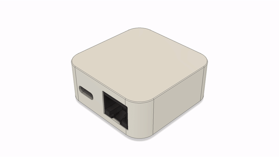
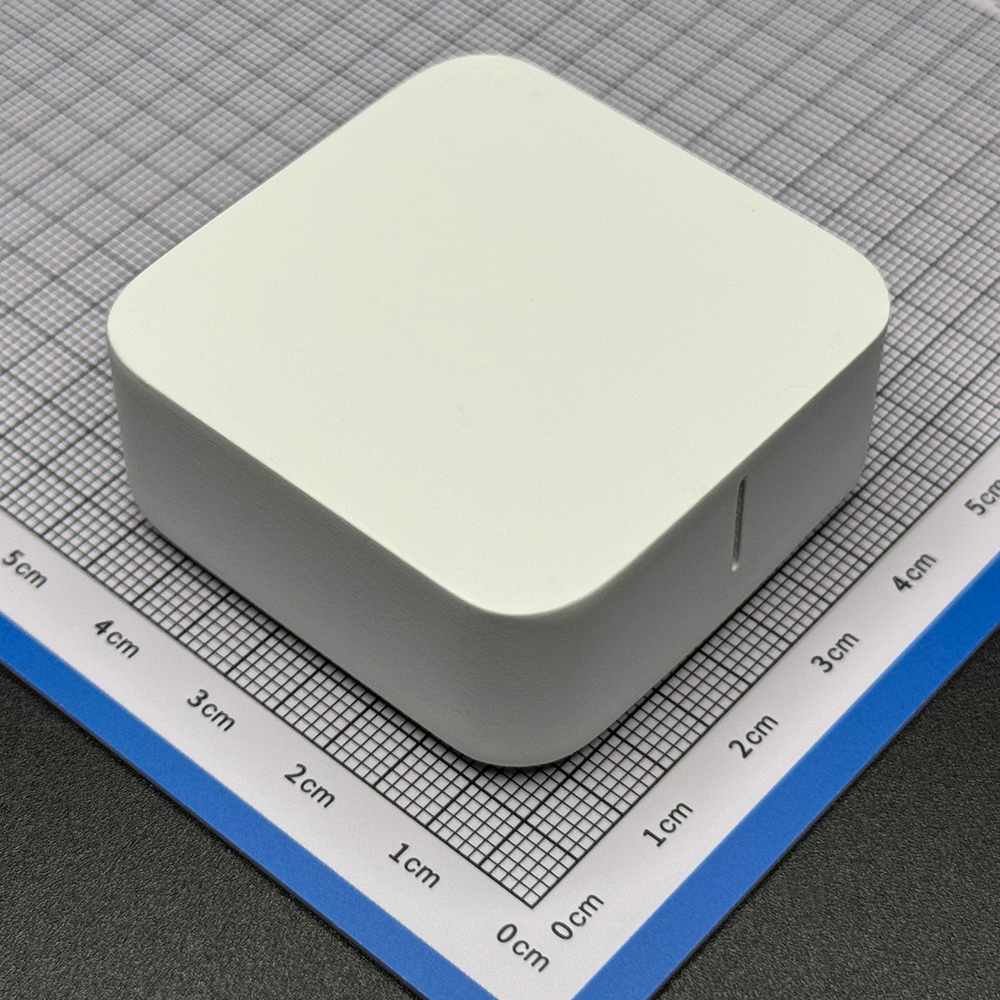
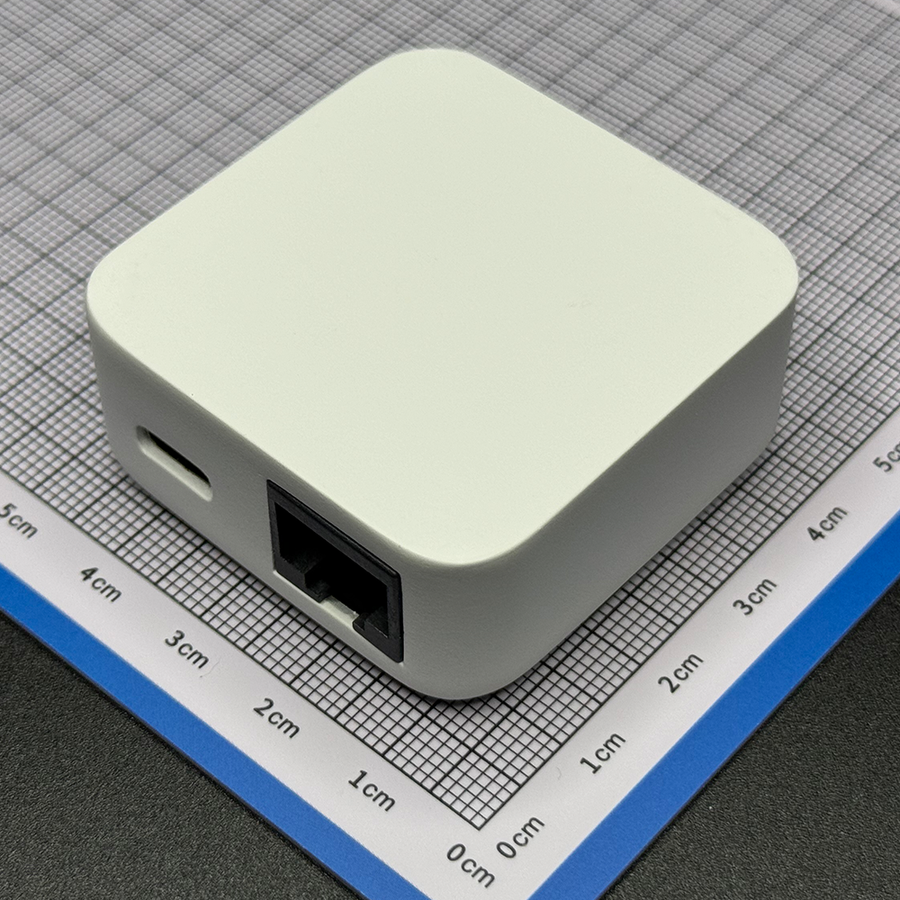
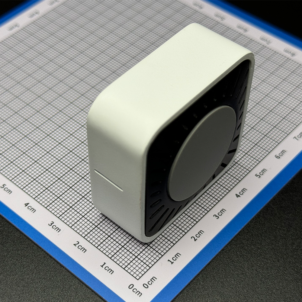
MINI Border Router
A very compact Thread border router, which can of course be used as a ZigBee gateway, and can even be used as a Wi-Fi router to convert wired networks to wireless networks.
MINI Border Router
Project Overview:
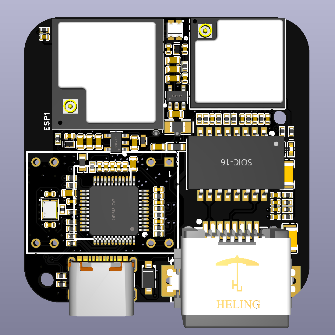
This project involves creating a MINI border router solution based on Espressif's ESP32-S3 and ESP32-H2 (Wi-Fi and 802.15.4), utilizing services such as LCSC PCB, 3D printing, and the LCSC online store.

The bilibili video link
project features compatibility
with ESP Thread Border Router,
bidirectional IPv6 connection
service discovery,
multicast forwarding,
NAT64
RCP update,
RF coexistence,
and a web-based graphical user interface.
Project parameters include
: Component
Specification:
Main chip
ESP32-S3-MINI-1U-N4R2,
Auxiliary chip
ESP32-H2-MINI-1U-N4;
Status indicator
WS2812
; Buttons
G0/G9 (Boot button, RST reset button)
; Slide switch;
USB toggle switch (selects between main and auxiliary chip); Input interfaces: USB-C wired network, RJ45
input ; Power supply: USB DC 5V input, PoE IEEE 802.3af (36V to 57V DC) ; Expansion I/O ; Rear pads for power and I/O; Device dimensions: 45 x 45 x 20mm; Device weight: 32g; Design principle: PCB'A (front and back); Finished board thickness: 1.6mm; Number of layers: 2; Board dimensions: 40 * 40 mm ; 3D schematic; Component Specification: Heatsink 14 x 14 x 6mm blue strip with thermal adhesive silicone pad, gray silicone pad, single-sided adhesive, 28 x 1mm diameter antenna , M-type ultra-small FPC (3DB 18 x 7mm), total cable length: 6cm, connector type: IPEX 3rd generation. Software description: Espressif ESP Thread Border Router SDK, Visual Studio Code + ESP IDF development environment. Physical demonstration . Notes : Difficulty of replication: ⭐⭐⭐ This project has many 0402 components, and the density is average. Please evaluate carefully before replication. The RJ45 network port has a corner that interferes with the bevel of the shell, requiring manual cutting of the network port plastic. Cost reference: Standard version, Simplified version, PCB'A ¥93 ¥55 (no PoE module) , Antenna ¥1.36 ¥1.36 , Heatsink ¥1.3 ¥1.3, Shell ¥28.7 ¥8.7 (unpainted) , Feet ¥0.11, None. Total ¥124.47 ¥66.36


Firmware_MINI-BR_v0.0.1_0x00_2024-09-18.7z
MINI-BR_0918.mp4
3D_MINI-BR.7z
PDF_MINI Border Router.zip
Altium_MINI Border Router.zip
PADS_MINI Border Router.zip
BOM_MINI Border Router.xlsx
90653
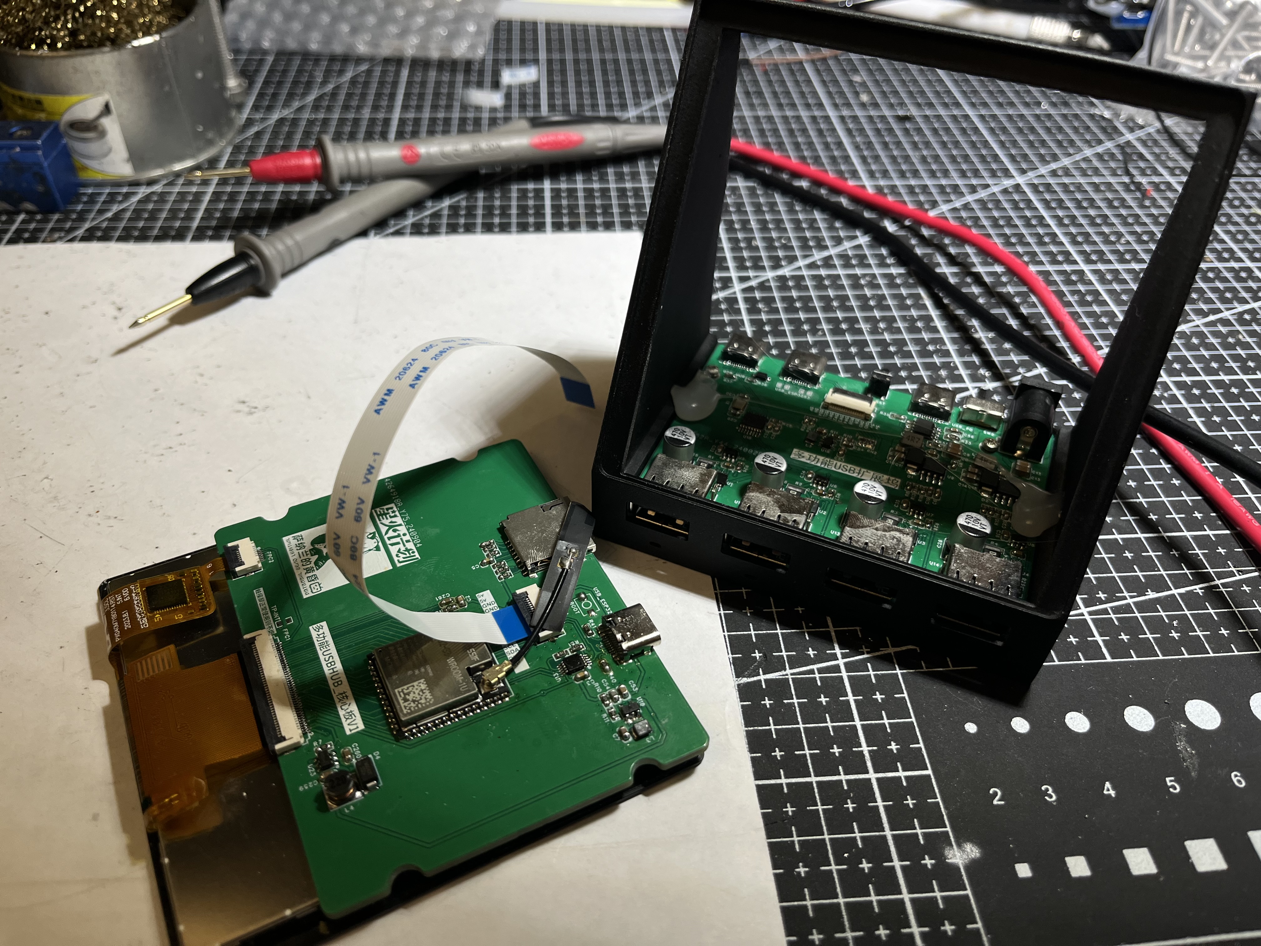
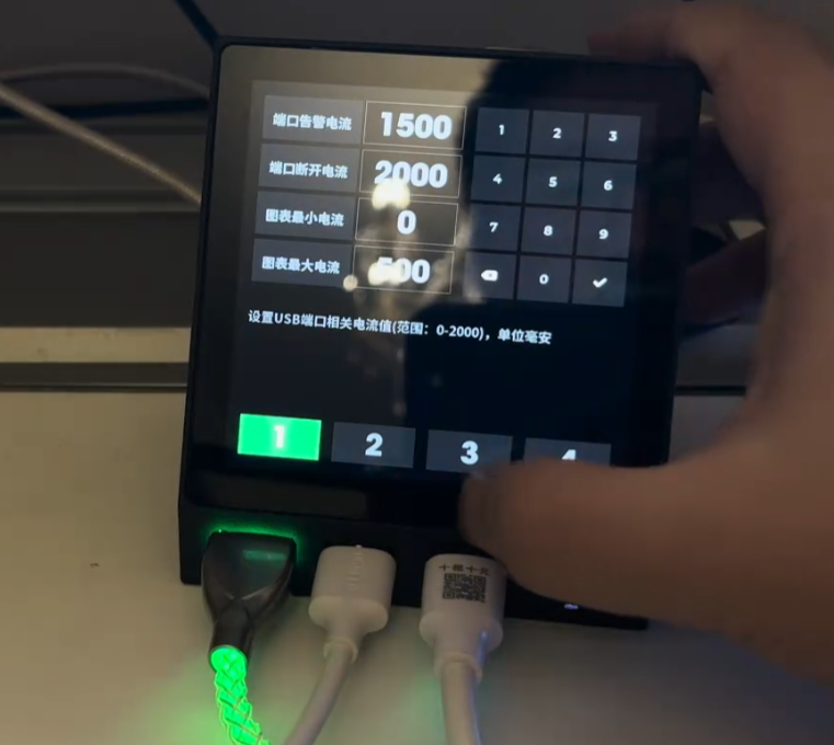
Multifunctional current and voltage detection USB hub
This multi-functional, independently isolated 4-port USB hub addresses the pain points of electronic debugging engineers . All ports feature
voltage and current detection, and each port has individually set warning and shutdown currents.
Shutdown of each port is controlled via touchscreen.
Additional standby apps include dynamic weather and a secondary screen.
As an electronics enthusiast, have you ever encountered this situation:
insufficient power supply to your computer's USB port, or backflow caused by parallel power supply failure, resulting in burnt-out USB ports? You
painstakingly solder a board, plug it in, and power it on, only to find that a short circuit elsewhere (like the backlight) causes excessive current in the USB port.
You might want to directly determine if the board is soldered correctly by
checking the power-on current. You could connect multiple USB devices and easily turn a specific USB port on or off
. Yes, this is the pain point I've encountered in the past two years of building electronics. Currently, my computer's USB ports can only output about 200mA of current; exceeding that results in errors, most likely due to backflow failure.
So, to meet my specific needs, I created a multi-functional USB hub
demonstration video:
https://www.bilibili.com/video/BV1LdtMe1E3S/
Main control section: uses an ESP32S3 module, plus a 4-inch 86-pin touchscreen as the interaction interface. Current
and voltage acquisition section: uses four INA226 chips to acquire four different voltage and current signals, transmitting them to the main control via I2C bus.
USB hub section: uses a CH334R chip, with four USB ports. Hub chip
power supply section: Supports 12V DC IN and PD spurious power supply. The PD spurious chip uses CH224K.
Electronic switch section: Uses SY6288CAAC 2A switch chip to control the VBUS of the 4 USB ports respectively.
Other: Four additional RGB LEDs are added to display the current status of each USB port (as an ambient light group).
The PCB is divided into a core board and a HUB board, facilitating future replacement of other screens or main controllers (such as long strip screens).
The screen supports multiple 4-inch touchscreens, both independent and integrated touchscreens.
Independent touchscreen models are verified. One example is the single-cable model from Taojingchi (https://item.taobao.com/item.htm?ft=t&id=757571286108&spm=a21dvs.23580594.0.0.1d292c1bCTukzD)
, and another is the 3.95-inch LCD screen/4-inch square screen/smart home RGB interface/resolution 480*480+86-cell IPS from Bohu (Taobao.com). The initialization codes for these two screens are different; macros
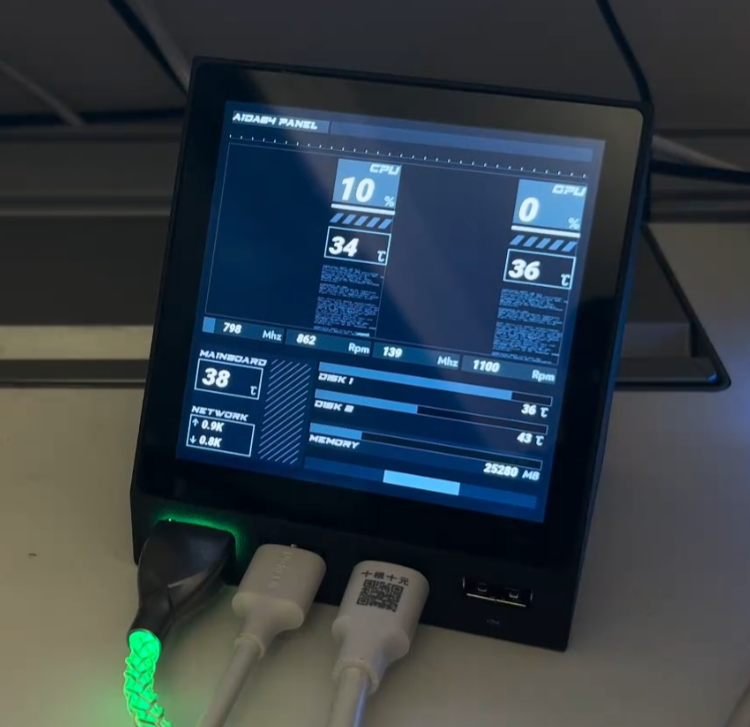
need to be modified in the source code. The HUB screen display is divided into four areas (buttons): 1, 2, 3, and 4, corresponding to the four USB ports on the left . Each USB port has four states. 1. Initialization failed: The button will not display anything, and the RGB light below the port will not light up. 2. Normal: The button will display current, voltage, and power normally. The RGB light below the port will change from green (0mA) to red (1000mA and above) according to the current value. 3. Manual shutdown: The button will have a gray background, and the RGB light below the port will be off-white. 4. Overcurrent warning: The port's digital display and current line graph will turn orange-red, and the RGB light below the port will be blue. 5. Overcurrent shutdown: The port will be disconnected and turn red. To reopen the port after overcurrent shutdown, press the switch once to enter manual shutdown mode, and then press the switch again to return to normal mode. The RGB light below the port will then be purple. Swiping left on the page will take you to the settings page, where you can individually set the four current attributes for each port (alarm current, disconnect current, minimum current in the graph, and maximum current in the graph) using the number buttons 1, 2, 3, and 4 below. Switch current setting for port alarm current: When the port current reaches this value, it enters overcurrent alarm state . Disconnect current: When the port current reaches this value, it enters overcurrent shutdown state. Minimum and maximum current chart: Set the minimum and maximum values of the Y-axis for the real-time current line graph . You need to press the checkmark on the virtual keyboard to trigger saving. When current monitoring is not needed in daily use, you can switch to the following APP and use the device as a secondary screen for the AIDA64 ambient group . This project obtains information from AIDA64's RemotePanel, parses it, and displays it through a custom UI. Run AIDA64 on the computer and set up the RemotePanel as required. On the device side, set up the computer's IP address (both need to be on the same network segment). Unique meter animation effects have been added to CPU and GPU usage, and a line graph effect that changes over time has been added. Animation effects have also been added to hard drive and memory usage. Dynamic weather clock : The weather clock in this project is the same as the one used in the previous iCRT project. The weather animation in this project comes from the HTC SENSE weather animation found online. HTC's mobile phone business has been discontinued for many years. If HTC informs me that it cannot be used, please let me know and I will delete it immediately. The weather updates every 3-5 minutes and currently comes from my Gaode API. If you have your own API, you can apply for it and fill in your usage. When the weather changes, there will be a smooth switching animation. In terms of clock, it includes the display of Gregorian calendar and lunar calendar, as well as common holidays and the 24 solar terms. MJPEG playback uses the latest and fastest SIMD decoding, which is the fastest decoding that the ESP32-S3 can do, 50-80% faster than ordinary decoding libraries such as JPEGDEC. The S3 is really struggling to drive this large screen RGB, so MJPEG playback is about 12 frames. It is recommended to set up some simple picture albums to play pictures. There is a gradient effect when switching. On all pages (except the settings page), swipe up to open the menu, click the menu to enter the corresponding function settings page, and click the arrow in the upper left corner to open the menu. Important Note for Replicas: Do not buy INA226 chips from disassembled devices; actual testing shows a failure rate of over 30%. If you encounter inaccurate readings or no display, it is recommended to replace the chip. For example, chips from LCSC are very stable. Thanks to LCSC for supporting the Spark Program. To avoid 5V backflow into the computer, do not connect the DC IN and PD IN during programming. Unplug the USB after programming and then reconnect it. You can use your own USB 1 or 2 ports to directly connect the core board with a USB cable for programming. Do not plug in the PD's USB and DC IN ports simultaneously. Although the switch supports two switching modes, it cannot be guaranteed that a short circuit between the 12V and PD's VBUS ports will not occur when the switch is toggled. Therefore, only one USB port should be connected at a time. The electrolytic capacitor capacity is not limited to 150uF; I soldered 470uF myself, and I feel the larger the better. The 0805 capacitors and resistors for the PD decoy port can be replaced with 0603 capacitors. The reason for using 0805 is twofold: firstly, it's copied, and secondly, others say that larger packages have higher withstand voltage. The 3D printing price for the casing is approximately 26 yuan (9600 resin). Source code containing a fully functional USB HUB page is available for download here and will be continuously updated.


esp32s3_usb_hub: Pure code for the ESP32S3 USB HUB METER, including complete USB HUB current meter functionality. The PCB and casing are open source on LCSC Open Source Plaza (gitee.com).
For those interested in building one, we recommend joining our DIY discussion group: 739444215.
====================================================================
Update:
Many people have already completed this (2024-11-05). If it proves useful, that's encouraging.
During the replication process, I encountered some common pitfalls, which I've documented here.
1. The core board's touchscreen I2C lacks pull-up resistors; these are located on the hub's baseboard. Therefore, if only the core board is connected, the startup process may get stuck at the I2C initialization stage for a long time.
Solution: Use an expansion board. Alternatively, you can modify the schematic yourself and add pull-up resistors to the I2C SDA and SCL lines of the core board.
2. The sampling resistor is 10 milliohms, called an alloy sampling resistor, specifically 10 milliohms (10mΩ) (R010), not 10 megaohms. Some replicas are sold as 10 megaohms, causing the system to interpret this as a large current and directly cut off the USB port.
3. If the corresponding INA226 address is not detected upon startup, the corresponding button will not be displayed. This can be used to determine which chip is faulty (or not soldered properly).
4. If only the programmed USB port is plugged in without the rear power supply, the current to ports 3 and 4 flows through the inductor; incorrect values are normal.
5. The shell step file has been provided in the group; you can modify it if needed.
USB_HUB_METER_source code.zip
libraries uses the arduino library.zip
3D Printed Shell.zip
PDF_Multifunctional Current and Voltage Detection USB Hub.zip
Altium Multifunctional Current and Voltage Sensing USB Hub.zip
PADS_Multifunctional Current and Voltage Detection USB Hub.zip
BOM_Multi-functional Current and Voltage Detection USB Hub.xlsx
90654
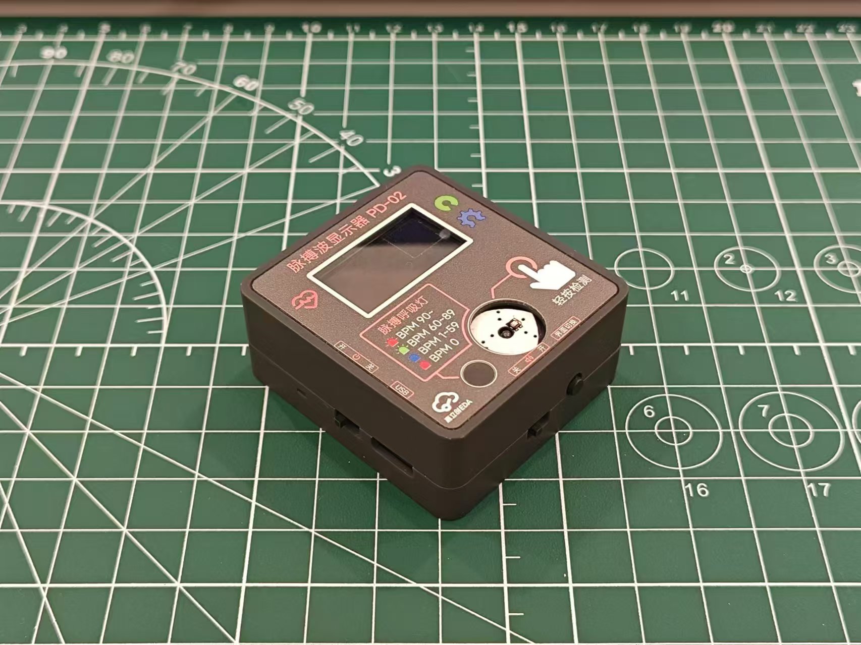
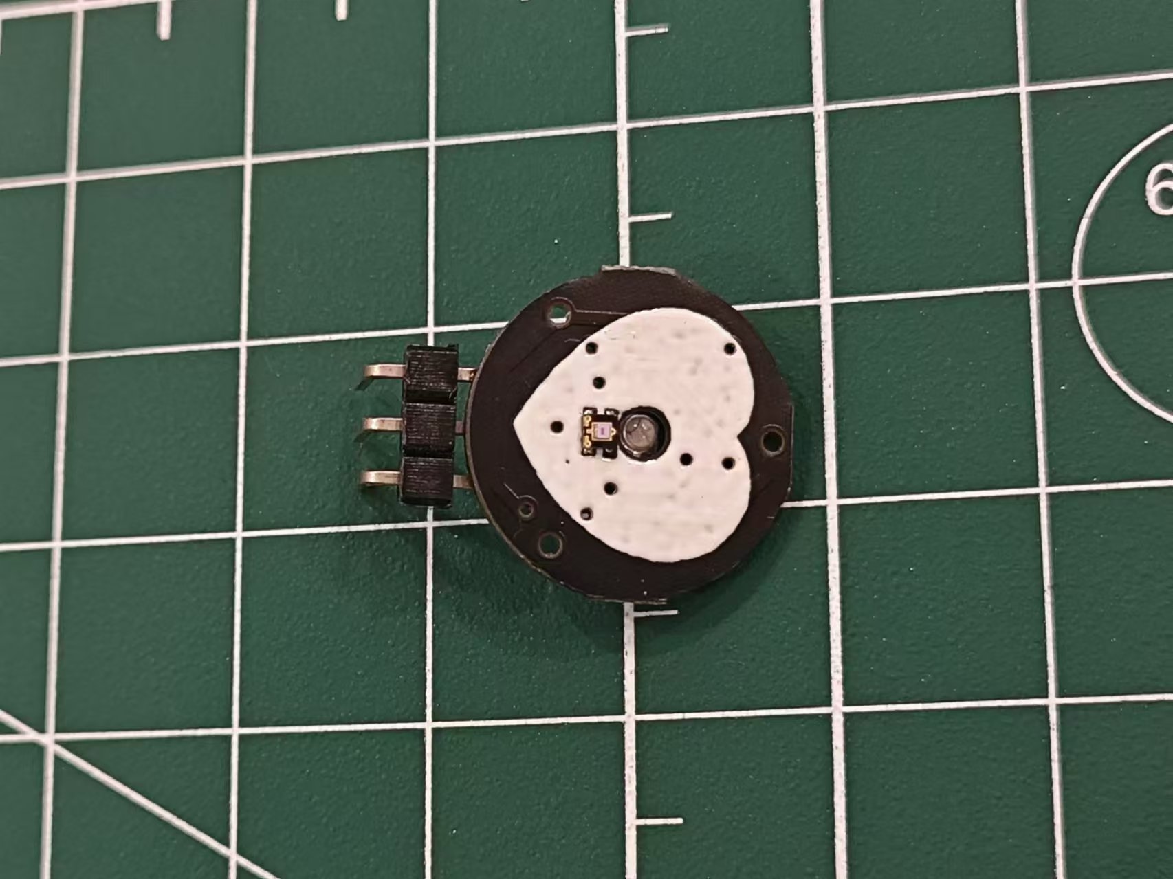
PPG-based pulse wave and heart rate display
PPG-based pulse wave and heart rate display: low cost and easy to replicate.
This project
introduces a pulse wave display using a PulseSensor as the heart rate sensor. Utilizing the PPG principle, green light is shone onto the skin surface (usually a finger), and a photoelectric sensor detects the intensity of the reflected green light. The intensity change curve represents the pulse curve. For convenience, a heart rate module is used to amplify the signal and fix the signal value near half the power supply voltage for easier reading.

Open Source License:
CERN Open Hardware License.
Features:
Pulse waveform display ,
heart rate display,
three-color pulse indicator, breathing light
, pulse beep,
multiple interface options.
Project Attributes
: This is the first public release of this project; it is my original work. This project has not won any awards in other competitions.
Project Progress
: 2024-04-03 Project Initiation
2024-04-06 Schematic and PCB Design Completed
2024-04-20 Added Function Buttons for Switching Interfaces
2024-04-24 Shell Design Completed
2024-04-28 Panel Design Completed
2024-05-11 Panel Improvement, Display Area Increased by 1mm
2024-06-01 Software Development Completed
2024-08-26 Data Compilation Completed, Open Source Project Released
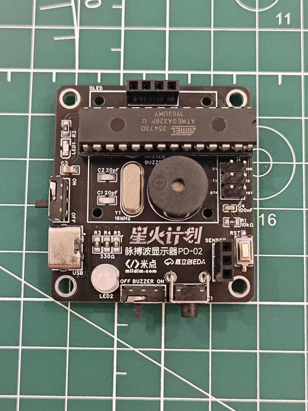
Hardware Design
MCU Uses ATMEGA328P-PU, Arduino UNO R3 Main Controller. Because the project was a replication and improvement of a foreign open source project, and I had just completed an oscilloscope training camp at the time, my knowledge was insufficient, so I could only use the original hardware design. I will continue to improve the design and choose a more cost-effective MCU when I have the opportunity.
The power supply section uses a Type-C 2P power supply. A lithium battery and power management chip could be considered for future upgrades to improve portability.
The display uses a 0.96-inch white OLED with a header and socket connection, allowing for easy removal and reuse in other projects.
The buttons are used for cycling through the display interface.
The program download section only has a reserved interface and does not have a built-in serial port chip; a serial port download tool is required for program download. An automatic program download can be achieved using a programmer with a DTR pin.
The LED section uses a three-color RGB LED fog light.
The buzzer section uses an active buzzer that only needs a high-level output to produce sound. Previously, a passive buzzer was used, requiring PWM drive. Testing revealed conflicts with other timers, causing sound distortion. Various methods were tried without success, presumably related to MCU performance; therefore, an active buzzer was used instead. A buzzer switch is also included, allowing the sound to be turned off independently. The software
design
is relatively simple. The heart rate sensor outputs an analog signal. Data is acquired via an ADC, processed by the PulseSensorPlayground official library to obtain the heart rate, and the waveform is processed to suit the screen display. Finally, it is displayed on the screen via the I2C protocol. The lighting section illuminates different colored LEDs according to different heart rate zones. The buzzer sounds each time a heartbeat is detected. Pressing a button triggers an interrupt and changes the mode. The OLED then displays different interfaces depending on the mode.
Physical
demonstration: [Image of physical model
without screen and heart rate sensor
assembly structure]

Panel
color scheme reference: Xiaohongshu @YUI_Design, https://www.xiaohongshu.com/user/profile/640eee95000000000f0105c8
Cost estimate:
Material
price:
PCB
(free)
, OLED
8.4 ,
Heart rate sensor
7.8,
ATMEGA328P
10,
Buzzer
0.6,
RGB LED
0.2
16MHz crystal oscillator
0.3 ,
resistors and capacitors
0.2,
pin headers and nuts
0.5,
screws and copper pillars
1 ,
switch
0.6,
LED
0.1,
Type-C female connector
0.1 ,
panel
1.3,
housing
14.43
, total
45.53.
Note: The above prices are unit prices and do not include shipping.
The panel needs to be ordered as a whole piece (300mm*200mm), priced at around 30. A total of 24 pieces can be cut, so the unit price is around 1.3.
If a panel is not needed, the outer shell can be modified by removing the top recessed area.
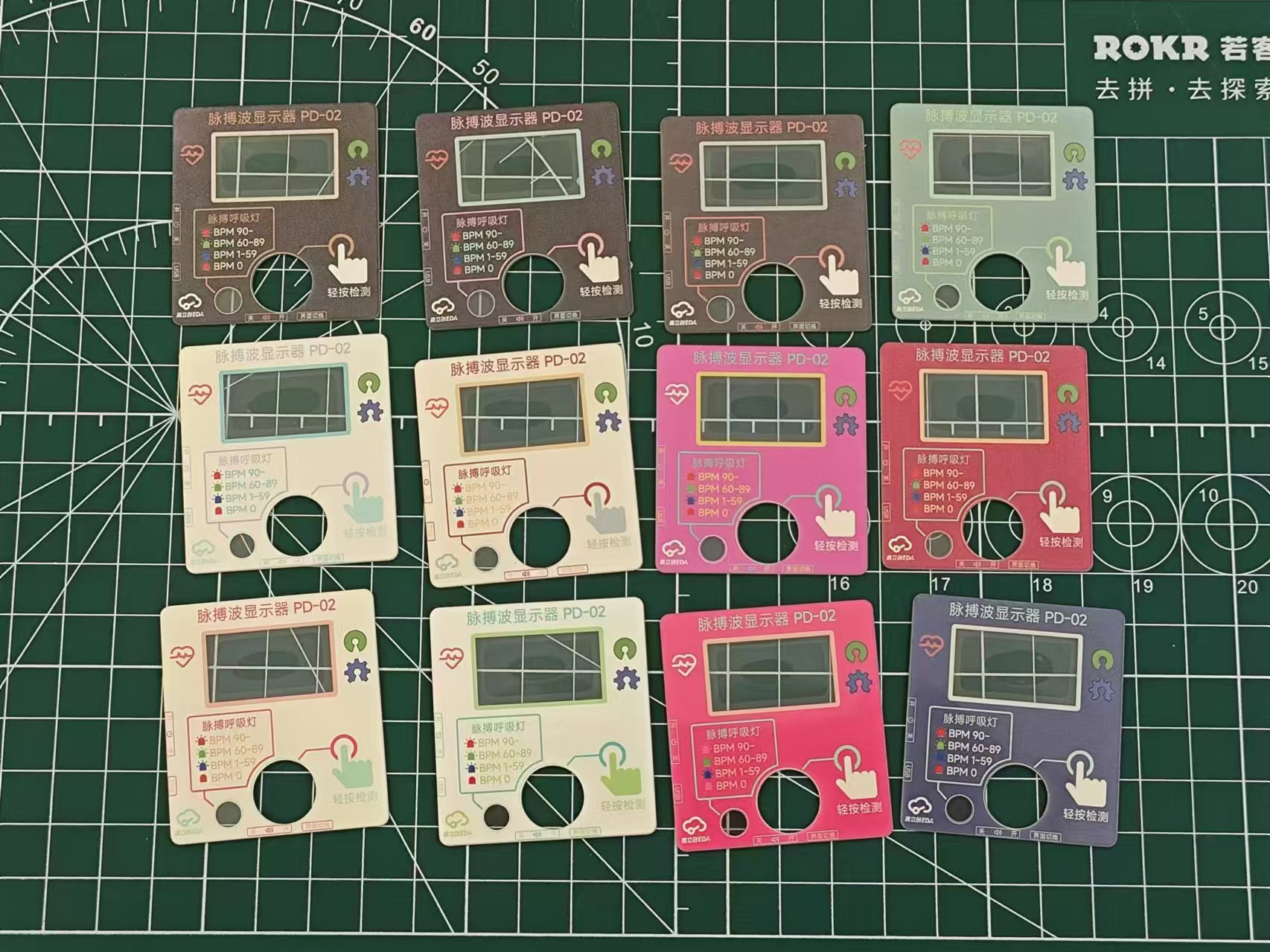
Replica Notes:
1. PCB
thickness : 1.6mm
2. 3D printed
outer shell material: Black;
support column material: LEDO6060
3. Panel:
Panel type: film panel
; number of panel styles: multiple; custom panel
size: 200mm*300mm
; number of panels: 1
; custom material: PET ;
printing material: high transparency
substrate thickness: 0.2mm;
printing method: front
bulge; buttons: no bulge ;
light blocking: standard;
adhesive: 3M9448A (universal).
Panel optional; if a panel is not needed, the outer shell can be modified by removing the top recessed area.
4. Components:
The following are components not listed in the BOM or with incorrect dimensions that need to be purchased via the provided link:
Heart rate sensor: https://m.tb.cn/h.gNKutecyDynzuaD?tk=Thvj3Uh60AO
OLED (starting with GND, 27.3*27.8mm): https://m.tb.cn/h.gmbY7lScoVBnXzm?tk=KS3p34kHjA1, Specifications: 0.96-inch white OLED module/4P
11mm 3p extended pin header: https://m.tb.cn/h.gmRGD0rT6kV4tS9?tk=9BJz34kN12t, Specifications: 3p, one-layer plastic height 11 pins length 8.5, single row
3+6mm positive bend pin header: https://m.tb.cn/h.gmzCu6yqvK189ws?tk=wnG934knb6l
6*6*6.5mm switch: https://m.tb.cn/h.gOHsXqQB6bcQF85?tk=wD1734knBaQ, Specifications: 6*6*6.5 4-pin vertical micro switch with
frosted RGB LED: https://m.tb.cn/h.gmzyniGQD26Mxix?tk=h9AZ34kLoZf
ATMEGA328P-PU: https://m.tb.cn/h.gOHtGOLzGVXJs9T?tk=TIUB34kouAa
Active Buzzer: https://m.tb.cn/h.gOHtzTn4JxDvVde?tk=IVsP34kptEU
Toggle Switch: https://m.tb.cn/h.gmRx6CjPJf2CoBZ?tk=MmrT34kLXOP, Specification: MSK-12D19 1P2T 3-Pin Toggle Switch
Type C 2P: https://m.tb.cn/h.gm0AktYsF17Kh8E?tk=jbJq34kp9f2, Specification: TYPE-C 2P horizontal
M2x4 screw: https://m.tb.cn/h.gmRCj4FwItln7Jx?tk=Bg9s34kqKWy
M3x8 screw: https://m.tb.cn/h.gmbZHYP3JFPG3L0?tk=Q3rd34kqkb2
M2x11 copper pillar: https://m.tb.cn/h.gmbZUfpZVVaXGkz?tk=yHp434kJKN6
1x4p female header: https://m.tb.cn/h.gmb0coOGh1UYSjb?tk=GV9034kJSrW, Specifications: 1x4p 2.54mm straight-through single-row female header, black (20 pieces)
Note: There are two types of heart rate sensors on the market. The other type has a very small signal amplitude, the reason is unknown. Try to purchase according to the above links.
5. Soldering
(1) The pin header on the heart rate sensor needs to be removed and replaced with the bent pin header. The relative position of the pin header and the module is shown in the figure below
(2). The OLED and heart rate sensor pin headers should be as horizontal and vertical as possible to avoid affecting the alignment of the back cover and panel
(3). The minimum RC package is 0603, which can be done directly with a soldering iron
(4). The RGB LED pin spacing is small, so care should be taken to avoid solder bridging
(5). The others are all plug-in packages, which are not difficult.
6. Burning:
Use a burning tool such as the CH340 burner.
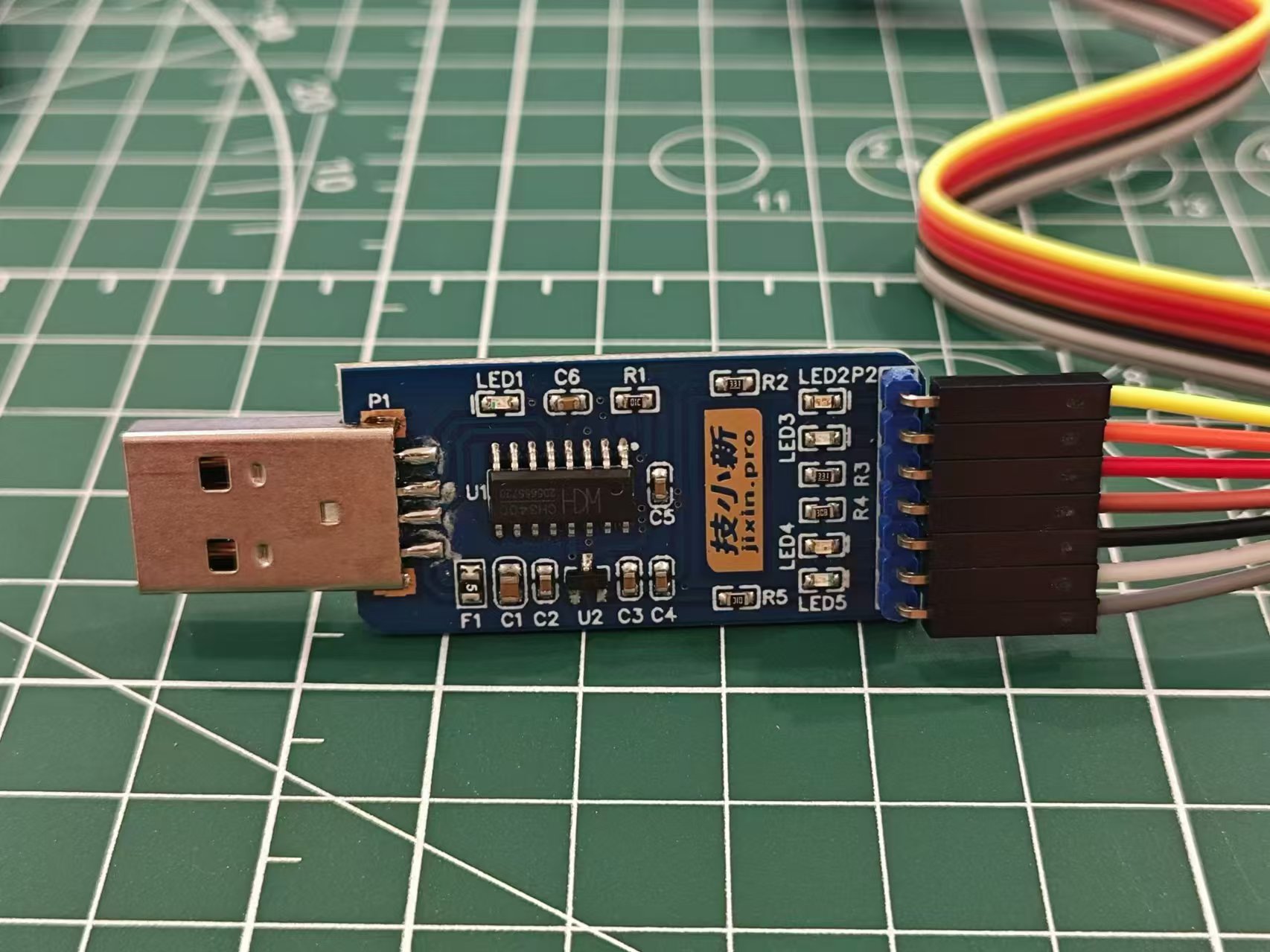
The connection is as follows:
PCB
burner
5V
5V
GND
GND
RX
TXD
TX
RXD
DTR
DTR
Use Arduino IDE to open the ino project file. First, download the necessary libraries:
PulseSensor Playground
Adafruit GFX Library
Adafruit SSD1306
. After selecting the serial port, click the upload button to complete the program burning.
If the DTR is not connected, you need to manually reset after clicking the upload button.
Note: The serial port method for burning programs is only applicable to 328p chips that have been burned with the boot program. If you buy it separately online, it is likely that it is a blank chip without the boot program. You need to use the Arduino UNO development board to burn the boot program to the chip first, and then you can use the above serial port method to burn other programs.
7. Assembly
(1) Paste the panel onto the upper shell
(2) First, fix the OLED screen onto the PCB using M2x4 screws*8 and M2x11 copper pillars*4
(3) Then install the heart rate sensor and fix the sensor with the 3D printed support pillar
(4) Place the whole thing on the bottom shell, install the upper shell, and fix the upper and lower shells with M3x8*4 screws to complete the process.
8. Use
(1) Insert the Type-C cable. It is recommended to use 5V power supply
(2) Slide the left power switch upwards to turn it on. The green light on the screen and heart rate sensor indicates normal operation. Gently press your finger on the heart rate sensor and wait a moment. The heart rate and pulse wave curve will be displayed on the screen.
(3) Press the lower touch switch to switch the display interface, which can be two lines with BPM, two lines without BPM, one line with BPM, or one line without BPM.
(4) The LED breathing light displays different colors according to different intervals. 0 is a solid red light, 1-59 flashes blue light, indicating a low heart rate, 60-89 flashes green light, indicating a normal heart rate, and above 90 flashes red light, indicating a high heart rate.
(5) Slide the lower switch to control the prompt sound. Left is off, right is on.
Attachment description:
Heartbeat_RELEASE.zip - Program code
Heart rate sensor support column V2-hole.STL - For components supporting the heart rate sensor, 3D printing orders are available.
Other
references include an international project: https://hackaday.io/project/167919-arduino-heart-beat-with-ecg-display-sound.
Improvements include: Hardware improvements such as reducing the PCB area and compacting all components to create a portable mini pulse wave and heart rate display; and software improvements such as optimizing the display interface by overlaying old curves with new ones for a more hospital-like look and adding function buttons for switching interfaces.
The PulseSensor heart rate sensor website is available at: https://pulsesensor.com/
Heartbeat_RELEASE.zip
Heart rate sensor support column V2 - small hole.STL
Demo video 1.mp4
Demo video 2.mp4
PDF_PPG-based Pulse Wave and Heart Rate Display.zip
Altium_PPG-based pulse wave and heart rate display.zip
PADS_PPG-based Pulse Wave and Heart Rate Display.zip
90655
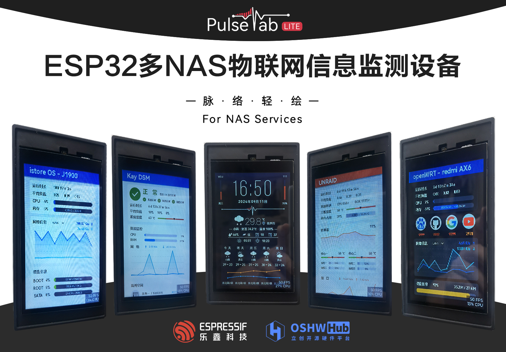
PulseTabLite: ESP32 Multi-NAS IoT Information Monitoring Device
Leveraging the powerful networking capabilities of the ESP32, an interactive IoT device was developed, solving the network connectivity and hardware health monitoring issues of NAS devices and enabling secure management of NAS devices. Peripheral sensors support environmental temperature and humidity adjustment, ensuring the NAS devices operate continuously in a healthy environment and state.
Project Introduction:
A NAS (Network Attached Storage) is a server specifically designed for data storage. It separates storage devices from the server via a network connection, centering on the data, thus enabling centralized data management. NAS devices require stable network connectivity and continuous hardware health monitoring to achieve backup and secure management of critical data. This project leverages the powerful networking capabilities of the ESP32 to develop an interactive IoT device that monitors the NAS network status, device hardware, and system health. It also includes necessary sensor peripherals to support environmental temperature and humidity adjustments, ensuring the NAS device operates continuously in a healthy environment and condition.
Product demo video: https://www.bilibili.com/video/BV1kb4ze6E7E/?spm_id_from=333.999.0.0&vd_source=c99f4cc51a936036bca99830e36262da
October 26, 2024 Update:
The LCSC ESP32 development board PulseTabLite computer monitor project has been completed and open-sourced. Interested users can access it after approval. Both hardware design and source code are open source.

(Photo of the two brothers)
Preface :
By completing this project, you will gain:
Proficiency in using Espressif ESP32 for embedded development;
proficiency in developing ESP32 products in the Arduino environment;
proficiency in writing drivers for buttons, touch sensors, temperature and humidity sensors, and photosensors;
learning to use the GPIO/PWM/ADC pin functions of the ESP32;
understanding the GPIO pin limitations of the ESP32-S3 and learning to use it for circuit design.
Learn embedded system usage and GUI front-end development:
Learn to use TFT_espi and LVGL to drive LCD screens;
be proficient in using Figma with LVGL for GUI design;
learn to edit LVGL code to achieve functional interaction;
be able to get started with the basic usage of the FreeRTOS system.
Gain a preliminary understanding of network communication technology and implement its application:
Be able to use communication protocols such as HTTP/UDP to achieve various functions such as network access and API acquisition;
understand the basic principles of SNMP for device communication.
Learn the basic project development process:
Experience the entire process of a project from idea to product implementation;
develop brand awareness, understand the connotation of project naming and brand packaging;
understand the brand development process.
I. Project Introduction
1.1 Requirements Analysis
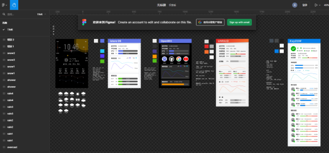
I am a deep DIY NAS enthusiast. Through several iterations of DIY products, I currently use an IstoreOS main router, an OpenWRT secondary router, and a dual-system NAS at home, including an underlying Unraid system and a DSM system installed on an Unraid virtual machine. The functions and concerns of each system are as follows:
IstoreOS Main Router:
Placed in the weak current box, attention needs to be paid to the temperature and heat dissipation of the box in summer;
the gateway network hub, DHCP service, and traffic monitoring.
OpenWRT Secondary Router:
Used as a secondary router in the study for internet access via VPN, requiring periodic testing of website connections;
using a Redmi AX6 (a high-end router) for upgrading, its hardware configuration is inferior to a software router, requiring monitoring of system resource usage.
Unraid NAS:
The underlying NAS system, running services using Docker and virtual machines, requiring monitoring of system and network resource usage;
the underlying system directly reads device resources, requiring monitoring of system temperature, hard drive usage, and fan operation.
DSM Synology NAS:
Used for storing and backing up important data, therefore requiring close monitoring of hard drive and storage space health, system operating status, and
system network monitoring.
Because NAS devices (including lightweight NAS systems) lack front-end system monitoring during daily operation, logging into a specific IP address webpage is required to understand the device's operating status, causing some inconvenience.
1.2 Functional Concept
Based on the above requirements analysis, the functions that this project needs to achieve are envisioned as follows:
a monitoring screen that can view the operating status of multiple NAS devices with one machine;
specific information monitoring for specific NAS system focus points;
a UI interface that fits the original system design, with intuitive and readable data;
simple operation, without cumbersome system and operation;
and the inclusion of functions such as clock and weather.
1.3 Brand Development
Brand development for a project refers to establishing and enhancing the brand image in the target market through a series of strategies and activities, thereby promoting the project's success and sustainable development. Although DIY enthusiasts primarily focus on learning and the fun of DIY, a successful project product will inevitably enhance its product image through brand development and promote it in the market by combining marketing strategies.
Since brand development involves more aspects of marketing, the discussion of brand development in this article will be brief. Additionally, this project has conducted a certain degree of brand development by leveraging Baidu's AI, Wenxin Yiyan; therefore, this section will use relevant discussions from Wenxin Yiyan.
1.3.1 Brand and Connotation (with Wenxin Yiyan)
The brand's name and connotation concisely reveal the project's core value. The core values of this project are: lightweight, accuracy, and intuitiveness.
Brand Name: NAS Pulse Tab Lite - NAS Pulse Lightweight
Brand Essence:
NAS (
Network Attached Storage) is the cornerstone of modern data centers, supporting the storage and sharing of critical enterprise and personal data. NAS PulseTabLite specifically addresses this core area, providing accurate and efficient performance monitoring and optimization services.
Pulse:
Like the pulse of the human body, NAS PulseTabLite can "sense" the "heartbeat" of the NAS system in real time—its operating status and performance fluctuations. This real-time monitoring and dynamic perception of performance ensures that users can understand the health status of the NAS system in a timely manner and quickly respond to potential problems.
Tab:
In the NAS PulseTabLite interface, users can easily browse different functional modules and monitoring indicators through simple "Tab" switching. Whether it's I/O performance, network bandwidth, or disk usage, everything is under control. This intuitive design allows users to quickly locate problems and improve operational efficiency. While pursuing comprehensive functionality, NAS PulseTabLite also emphasizes lightness and simplicity
.
Its simple interface design and convenient operation process allow users to easily get started and quickly master the product's usage without cumbersome settings or complicated steps. This lightweight design concept brings users a smoother and more efficient user experience.
The name "NAS Pulse Light Drawing
" embodies the product's core technological features (comprehensive monitoring and in-depth understanding of NAS system performance), conveys a simple, intuitive, and easy-to-use product experience, and also possesses a poetic aesthetic.
"Pulse" – In Chinese, "pulse" usually describes the internal connections and order of things, like the blood vessels in the human body, connecting various parts. Here, "pulse" is used metaphorically to describe the data flow, performance changes, and connections between various components within the NAS system. It implies that this product can deeply understand the "blood vessels" of the NAS system, providing users with clear and accurate performance monitoring and status display. "
Light Drawing" – This term expresses the product's interface design and user experience. "Light" represents simplicity and portability, while "drawing" suggests that users can easily perform various operations on this interface, as freely and smoothly as drawing. Therefore, "Light Drawing" conveys a simple, intuitive, and easy-to-use product experience, enabling users to easily control the performance and status of the NAS system.
1.3.2 The brand packaging
main logo design is as follows:

II. Hardware Implementation
The hardware implementation of this project is not complex, mainly including the screen and touch circuit, peripheral sensing circuit, and auxiliary power supply circuit, serial communication circuit, and ESP32 peripheral circuit.
In addition to supporting this project, this hardware can also leverage the powerful communication capabilities of the ESP32 chip to implement different IoT functions through different software development, including but not limited to smart home control, information broadcasting, and network communication support.
2.1 Schematic Diagram Description
2.1.1 The display screen and touch circuit
adopt an EYA 4-inch LCD capacitive touch screen with a built-in 40-pin FPC. The display interface supports SPI and parallel communication protocols; the 8-pin touch interface supports I2C communication protocol.

Key points of the display circuit:
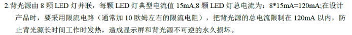
According to the screen development manual, the board has 8 onboard LEDs, and the total backlight power supply current should not exceed 120mA. Therefore, a 10-ohm current-limiting resistor is connected in series at the LED_A interface;
the backlight control circuit should use a transistor, with the gate connected to the pin with PWM function;
the display interface selects the high and low voltage levels M0-M2 according to the communication protocol.
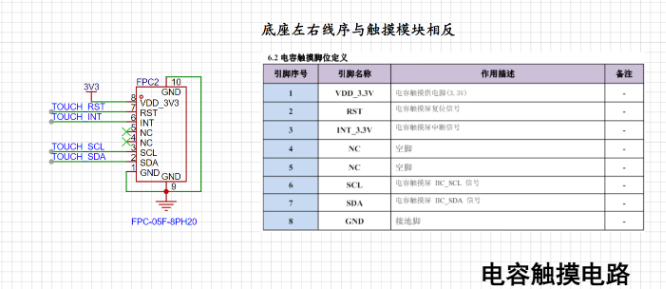
Key points of the capacitive touch circuit:
The 8-pin FPC socket interface with the serial number C2856797 selected here has the reverse pin sequence from the screen interface. Note that you need to check the correct connection before powering on;
RST can be connected to the RST pin of the LCD.
2.1.2 ESP32 Related Circuits
: For scalability considerations, this project uses ESP32-S3 WROOM N16 R8 Module. The following requirements should be noted in the design of the chip circuit (summarized from the chip design manual):
Note the minimum circuit requirements for the WROOM package in the design manual
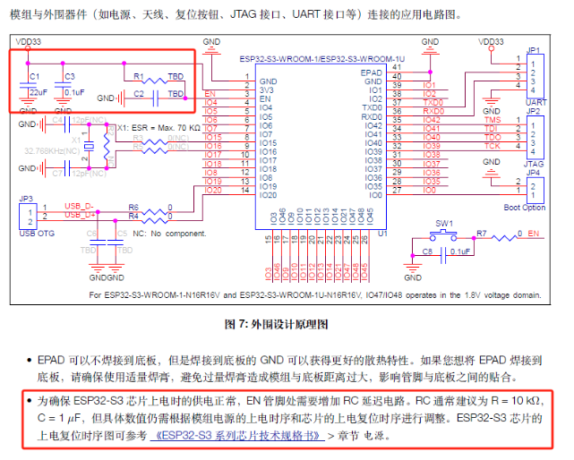
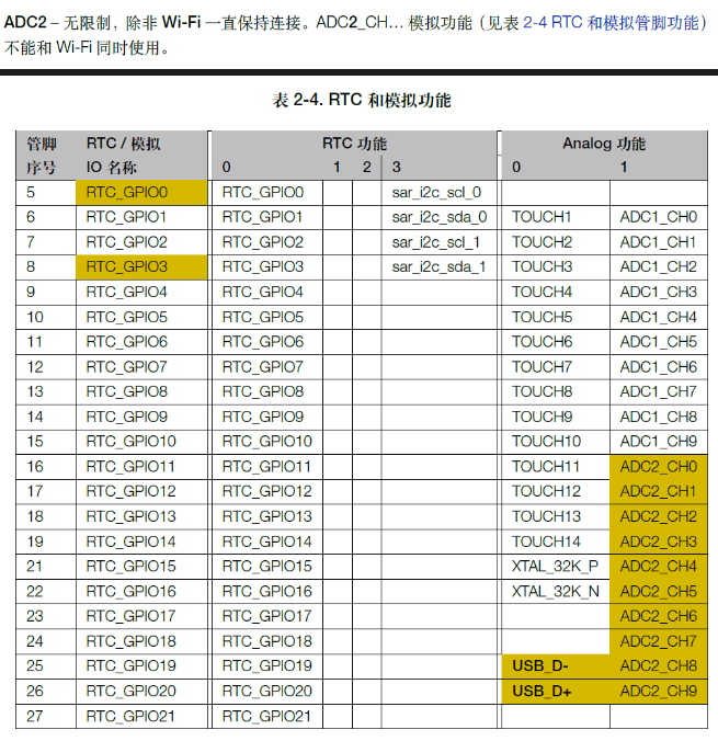
. IO35/IO36/IO37 cannot be used when there is SPI RAM;

some GPIOs that support ADC functions cannot be used under continuous WIFI network conditions (yellow part in the figure below);
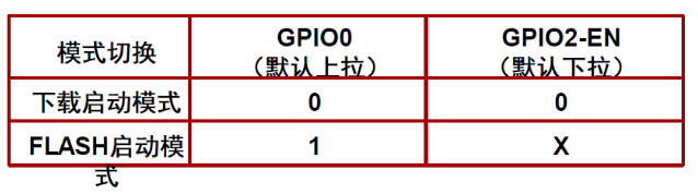
the serial port automatic programming circuit connects to the GPIO0-BOOT and GPIO2-EN pins, and uses two transistors to implement
SPI. The design should avoid SPI0/SPI1, and the default SPI pins should be used as much as possible

. Other circuits are not described in detail, and are all basic power supply, programming, button and sensor circuits.
2.2 Layout Instructions
2.2.1 Screen FPC Socket
Note the FPC cable direction in the LCD user manual. Check whether it is reversed before layout and power-on to prevent damage to the circuit.
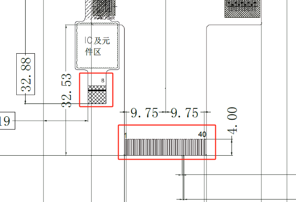

There should be no component layout in the FPC area; at the same time, open holes in the board for wiring as appropriate.
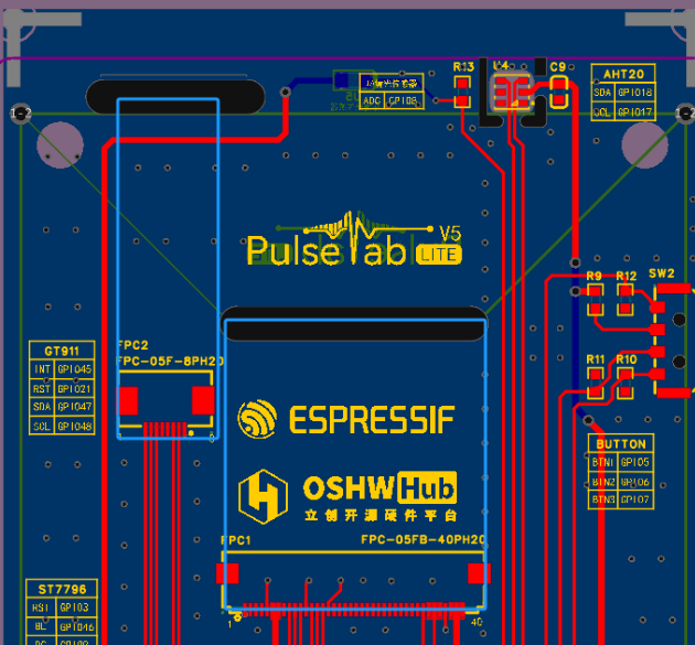
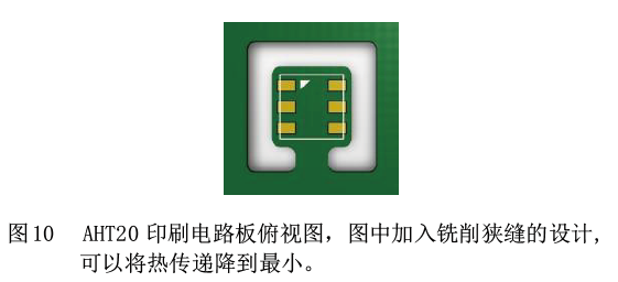
2.2.2 AHT20 Due to the large screen size in this project, the AHT20 temperature and humidity sensor's
heat generation from the screen and chip will cause it to exceed normal values. Therefore, the layout requirements in the instruction manual should be followed during the design process. Keep it as far away from heat-generating areas as possible to reduce heat conduction and increase ventilation.


2.2.3 Ambient Light Sensor:
This sensor is located on the front of the machine and is the only component located on the back of the PCB. When soldering, ensure all other components are reflowed before manual soldering.

III. Software Implementation:
The hardware design of this project allows for expansion while ensuring functionality; however, software implementation is the focus of the project development. It utilizes ESP32 to implement various network communication services and achieves information acquisition and interaction functions through task scheduling design and front-end GUI development.
3.1 Functional Block Diagram:

The software layer of this project uses the FreeRTOS system for backend task management and LVGL for frontend task processing. Functional implementation mainly includes network connection, sensor driver, and interface interaction.
Backend tasks include: startup program, device driver, capacitive touch startup and interface startup program, date and weather service program, and NAS information service program;
frontend tasks include: weather UI update, clock and date UI update, and NAS information panel UI update.
3.2 Capacitive touch and LVGL configuration:
The display driver is implemented using Ardiuno's TFT_espi and LVGL libraries, and the touch driver is implemented using the bb_captouch library.
TFT_espi configuration points:
Configure LCD pins and clock frequency;
implement the LCD screen ST7796 driver and configure the screen size.
LVGL configuration points (this part still needs further optimization)
: Configure the color mode as 16-bit RGB565;
use custom memory, configure the screen refresh rate, configure the clock frequency;
configure the screen buffer buffer_size = screenWidth * screenHeight / 30.
bb_captouch configuration points:
Configure the touch driver as GT911 and the communication method as I2C;
configure the touch driver pins;
configure the touch parameters. This driver can support up to 5-point touch.
3.3 Peripheral driver configuration:
Peripherals mainly consist of various sensors and buttons.
AHT20 temperature and humidity sensor configuration points:
This sensor uses the I2C communication protocol. Consult the device development manual. Since the capacitive touch has already used I2C configuration, the TwoWire Wire1 = TwoWire(1); parameter in the Wire library is used for configuration here. Wire1.begin(aht20_sda, aht20_scl); // Join I2C bus.
Key points for ambient light sensor configuration:
This sensor requires the use of the ESP32's analog-to-digital converter (ADC). Referring to the development manual, due to the need for continuous wireless connectivity in this project, there are some ADC pin limitations in the hardware design, which are emphasized here again.
Configure the pin mode as pinMode(LIGHTPIN, INPUT); and use analogRead(LIGHTPIN) to read data.
Button configuration is relatively simple and will not be elaborated here.
3.4 Time and Weather Function Implementation
Key points for the time function:
Time synchronization is achieved using Alibaba Cloud NTP servers, with three servers configured, such as ntp1.aliyun.com;
time zone offset: Beijing uses GMT+8, calculated in seconds as gmtOffset_sec = 8 * 3600; Daylight saving time is not used and is configured to 0;
Due to a delay of 5 to 10 seconds between clock configuration and time acquisition and update, investigation revealed a statement in the getLocalTime(&timeinfo) function that configured a time delay, causing a lag in time acquisition at boot time. This has not yet been optimized (experts are welcome to provide guidance).
Key points for the weather function :
After testing multiple service providers, the service provider "http://t.weather.sojson.com/api/weather/city/101190801" was ultimately selected. This website is stable, free, requires no registration, and has a short data acquisition cycle. See https://www.lanol.cn/post/33.html for details;
data parsing uses the ArduinoJson library.
3.5 NAS Information Communication
NAS communication is based on SNMP service. This communication protocol was chosen because iStorOS, OpenWRT, Unraid, and DSM systems are all based on Linux, making SNMP a universal communication protocol.
Key points of SNMP protocol communication:
Most OID and MIB trees based on Linux systems are universal, facilitating the acquisition of system, network, and hard drive usage information;
please note that when using SNMP, the server-side snmpd should be installed on the Linux-based NAS device;
the DSM system has performed secondary development of SNMP MIBs on its official website, and tutorials on using DSM's SNMP can be found online. The DSM SNMP user manual can be found at https://global.synologydownload.com/download/Document/Software/DeveloperGuide/Firmware/DSM/All/chs/Synology_DiskStation_MIB_Guide_chs.pdf.
Disadvantages of SNMP communication:
Because SNMP is based on the DUP protocol, communication here is asynchronous. When performing a large number of OIDs, especially when using WALK for device polling, the single communication cycle is long; at the same time, some data in the Linux snmpd protocol is updated every 5 seconds. Therefore, NAS information communication based on SNMP services cannot achieve second-by-second updates, which limits the monitoring of information requiring high synchronization.
3.6 GUI Front-end Development
The GUI front-end development uses Figma for UI design, and then imports the relevant material files into the SquareLine Studio environment for LVGL GUI development.
Figma is a vector graphics editing software with outstanding lightweight and ease of use features, allowing user interface (UI) and user experience (UX) design to be completed on the web page.
SquareLine Studio is an innovative visual drag-and-drop UI editor designed for embedded and desktop applications. Originally a platform for LVGL development, it has excellent compatibility with LVGL. This software greatly reduces the learning curve of LVGL development statements. Through graphical interface design, real-time interactive preview is possible, and program files can be exported after the design is completed.
The software trial lasted for 30 days, during which interface design could be completed (the trial period has now expired, and screenshot previews are no longer possible).
IV. Future
Functionality Improvements:
This project participated in the ESP32 IoT project, resulting in a tight development cycle. The LVGL design software is a paid service, and the project development, focused on learning and personal application, has certain limitations, such as the lack of a device configuration GUI design. The next step is to optimize the device configuration and NAS UI display interface.
Initially, device monitoring on Windows systems was also considered, therefore, relevant function interfaces for Windows system information monitoring are included, and these will be improved in the next step.
Regarding product optimization,
this project uses the SNMP protocol for communication. The project development allowed me to learn the principles and applications of this communication protocol. However, the SNMP protocol has drawbacks such as high latency. The next step is to use the mainstream AIDA software for optimization and development to improve real-time performance.
Due to the tight development cycle, memory debugging and optimization consumed approximately 50% of the time. Therefore, the 3D shell of the project was designed using JLCPCB EDA, and its personalization and operability need improvement.
This project connects NAS devices to the Internet of Things, realizing information access for personal electronic devices and showcasing the AI+ALL-in-one IoT concept. The next step is to build upon this foundation and further develop the system by leveraging Espressif Systems' ESP RainMaker solution and ESP HomeKit SDK framework to enable IoT device connectivity. This will allow for features such as mobile terminal monitoring, autonomous network optimization, and automatic temperature and lighting adjustment, helping NAS devices maintain optimal operating conditions in real time.
Gerber_PCB1_2_2024-08-30.zip
SCH_Schematic1_2024-08-25.pdf
BOM_Board1_P


 京公网安备 11010802033920号

 HLMP-CW39-XV400


