This project introduces
a dual-channel 1-6s lithium battery charger with passive balancing functionality. It uses an STM32G474 as the main controller and employs a PID control loop. LVGL has been ported, and a 2.8-inch 320*240 capacitive touchscreen is used as the input device. The UI is designed using GUI-guider.
Specifications include
a maximum charging current of 12A,
a single-channel maximum input current of 12A,
and an output voltage range of 0.2-26V.
Passive balancing functionality is also included.
Project progress:
2024/2/2: Dual-channel charging functionality implemented, currently only supporting lithium-ion batteries.
2024/2/27: LVGL porting completed; some UI code completed, enabling screen control of the charger.
2024/3/4: Hardware modified; LCR circuit removed; battery internal resistance measurement performed using alternative methods; voltage sampling circuit optimized.
2024/3/15: New board soldered and verified; all modifications are correct.
2024/7/27 Many modifications were made during the process, such as optimizing the battery voltage sampling circuit and removing the output diode to give the board bidirectional functionality. As of today, the project is basically complete, but some functions are still not fully written.
Hardware principle introduction :
Overall block diagram.
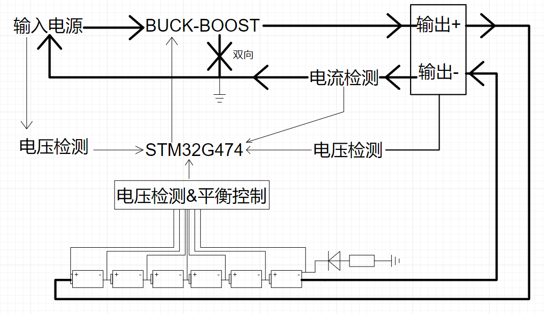
This diagram shows the principle block diagram, where an STM32G474 controls a BUCK-BOOST circuit to achieve constant current and constant voltage charging of the battery.
Battery voltage sampling and equalization control:

This diagram shows the battery voltage sampling block diagram.
Battery 1 is directly connected to a differential amplifier with a gain of 0.5, and the voltage of battery 1 is obtained by using an ADC to acquire the output. Battery 2
is also directly connected to a differential amplifier with a gain of 0.5, and the voltage of battery 2 is obtained by using an ADC to acquire the output
. Batteries 3-6 also use differential amplifiers for sampling, but because the common-mode voltage is too high, the voltage must be reduced. Therefore, the voltages of batteries 2-6 will be reduced to 1/6 of their original value (gain 0.16666667). Using two single-pole four-throw analog switches (CD4052), the voltages across the terminals of one of batteries 3-6 can be simultaneously obtained. These voltages are then fed into a differential amplifier to obtain the voltage of a single battery from 3-6.

This diagram shows the battery balancing control.
R42-R51 in the diagram are the voltage scaling resistors for batteries 2-6 mentioned above.
The purpose of R84 and D37 is to prevent the negative terminal of battery 1 from being directly grounded. If it is directly grounded, the output control switch MOSFET will lose its function and cause a series of problems.
Passive balancing is achieved through resistor discharge. R22-R27 are discharge resistors, Q10-Q15 are discharge switches, and the network labels CHA_BAT1_IO-CHA_BAT6_IO are the control signals for the discharge switches (0 for off, 1 for on). Taking
the discharge circuit of battery 5 as an example (assuming 6 batteries are inserted at this time, each at 4.2V), the source of Q11 is 21V-0.3V. = 20.7V, this 0.3V is the voltage drop across D37. When CHA_BAT5_IO is 0, the digital transistor is off, so R37 is essentially floating, Vs = Vg, and Q11 is off. When CHA_BAT5_IO is 1, the digital transistor is on, and R38 and R20 make 1/2Vs = Vg, that is, Vs = 20.7, Vg = 10.35. At this time, Vgs = Vg - Vs = 10.35 - 20.7 = -10.35, and Q11 turns on, starting the discharge. R37 exists to prevent Vgs from exceeding its absolute maximum value and damaging

this circuit. This diagram shows the battery voltage sampling circuit (3-6).
Initially, it's not clear, but the diagram below makes it clear.

Some may wonder how the gain of this circuit is calculated? Is it feasible to feed the decayed battery voltage into a differential amplifier in this circuit? With a high output impedance and a low input impedance, this differential amplifier circuit shouldn't be usable, right? However, the reality is that V+ and V- are directly connected to the battery terminals, and the op-amp's output voltage is equal to 1/2(V+ - V-), meaning the gain is 0.5. Here's the result directly: G = R18/(R16+R19+R14||R10)/(1+R14/R10). Let's look at a simulation diagram below.

From the diagram, we can see that the circuit's input voltage V+ = 15V, V- = 10V, and output is 2.5V, which matches the above calculation. To rule out any non-coincidence issues, we changed the values of R19 and R20 to 18350 ohms. Calculating G = 110000/(20000+18350+100000||20000)/(1+100000/20000) = 0.333333333, the output becomes 5*0.333333333 = 1.666666665, which matches the output in the graph perfectly.
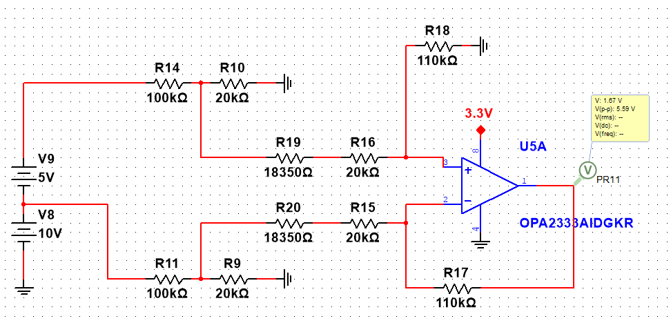
Some might notice that an analog switch is connected between the voltage divider resistor and the differential amplifier. This introduces the internal resistance of the analog switch, leading to inaccurate gain calculations. Indeed, the 70-100 ohm internal resistance of the analog switch slightly alters the gain. R19 and R20 in the diagram are used to simulate the internal resistance of the analog switch. If the internal resistance is set to 100 ohms, the impact is minimal, as 100 ohms is relatively small compared to the kiloohm level.
Auxiliary Power Supply:

This circuit reduces the input DC voltage to around 5V for use by all subsequent chips. I'm not sure if I bought a fake chip, but the datasheet states VREF = 0.81V, but after soldering and powering it on, the output was incorrect. I eventually discovered that VREF was 0.6V. I then modified the feedback resistor to output around 5V. Currently, the feedback resistor in the schematic is designed for VREF = 0.6V. If VREF = 0.8, the lower voltage divider resistor should be 13K and the upper voltage divider resistor should be 68K. The inductor in the diagram is 4.7uf, and the D62 Schottky diode is essential for reverse connection protection.

This circuit boosts the 5V voltage to 12V for the cooling fan and gate drive. The D58 doesn't need to be soldered; it's only used during debugging. Using a buck-boost structure reduces the input voltage.

These are two LDOs, one for the microcontroller and the other for the op-amp. A capacitor marked in the diagram is crucial; it's a strange issue I encountered during debugging. Although I solved it, adding it improves stability.

This is the VREF for the microcontroller's ADC. A 1-ohm resistor is connected in series with the output capacitor to improve ESR. This device has requirements for the output capacitor's ESR; a higher ESR is better. MLCCs have too low ESR, hence the 1-ohm resistor. The seventh pin is grounded due to layout issues; you'll understand once you've looked at the PCB. The datasheet doesn't show internal connections for the NC pin, which is fine, but the DNC pin must remain empty and cannot be connected to any network.
Main Circuit:
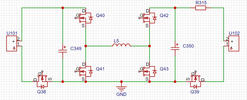
This is the main power circuit, including input/output interfaces, input/output capacitors, six MOSFETs, and one inductor. It enables bidirectional energy flow. Q38 is directly controlled by +12V. As long as the +12V network has sufficient voltage, Q38 will turn on directly. Q38 is mainly used for reverse connection protection. Initially, Q38 is off. If the input is normal, the current flows from the source (S) terminal through the body diode to the drain (D) terminal and then into the negative input terminal. This is the normal circuit. The auxiliary power supply outputs gradually. When +12V is applied to Q38, Q38 turns on. At this time, GND is connected to the negative input terminal, and there is no longer a diode voltage drop. If the input is reversed, there is no current circuit, the auxiliary power supply will not work, and Q38 will not turn on.
Q39 is used for reverse connection protection at the output. When the battery is reverse-connected at the output, there is no circuit, and therefore no current. The remaining components form a four-switch buck-boost circuit with buck-boost functionality.
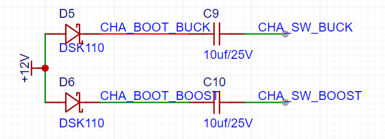
The diagram shows the bootstrap capacitor section for the gate drive. A 10uf bootstrap capacitor is used because in buck or boost mode, one of the half-bridge PWM frequencies is inevitably very low; a smaller capacitor would not provide sufficient charging.

This circuit samples the output voltage. Because the output ports are not grounded, differential sampling is required, and the port voltage is reduced by a factor of 11 in the diagram.
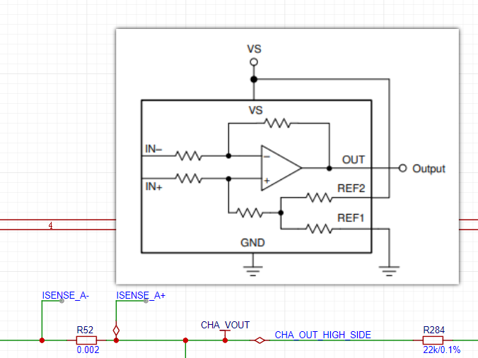
This is a current sampling circuit. The diagram shows the internal block diagram of the INA240. To monitor bidirectional current, a REF input is required. Because the INA240 integrates voltage divider resistors, REF1 is grounded, and REF2 is connected to VS. At this point, REF is VS/2 = 1.65V. This 1.65V REF is applied to the V+ and V- terminals of the INA240 op-amp. This 1.65V is not only applied to the op-amp but also loaded onto the high side of the output port through the resistor next to IN+. What problem does this cause? Actually, there isn't a major problem. It mainly charges the input capacitor, causing a slight voltage rise. This results in a certain voltage at the output port even when the circuit is in a static state. In this project, I added a 10kΩ resistor at the output port, but even so, the output port still has a voltage of 10-30mV. Without it, the voltage is around 140mV. This problem doesn't exist when sampling the low-side current because the IN- terminal is directly grounded. To achieve a static output of 0 under current conditions, the only options are to increase the output resistor or enable the upper MOSFET on the boost bridge arm. However, the upper MOSFET on the boost bridge arm cannot be enabled arbitrarily, as this is a charger with a battery plugged in at all times. Enabling the upper MOSFET would cause reverse voltage flow, so there's no good solution.
Heat Dissipation Design:
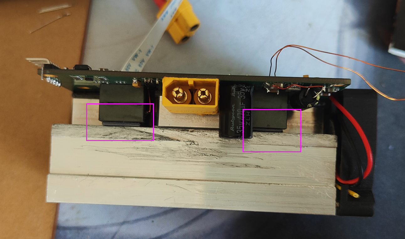
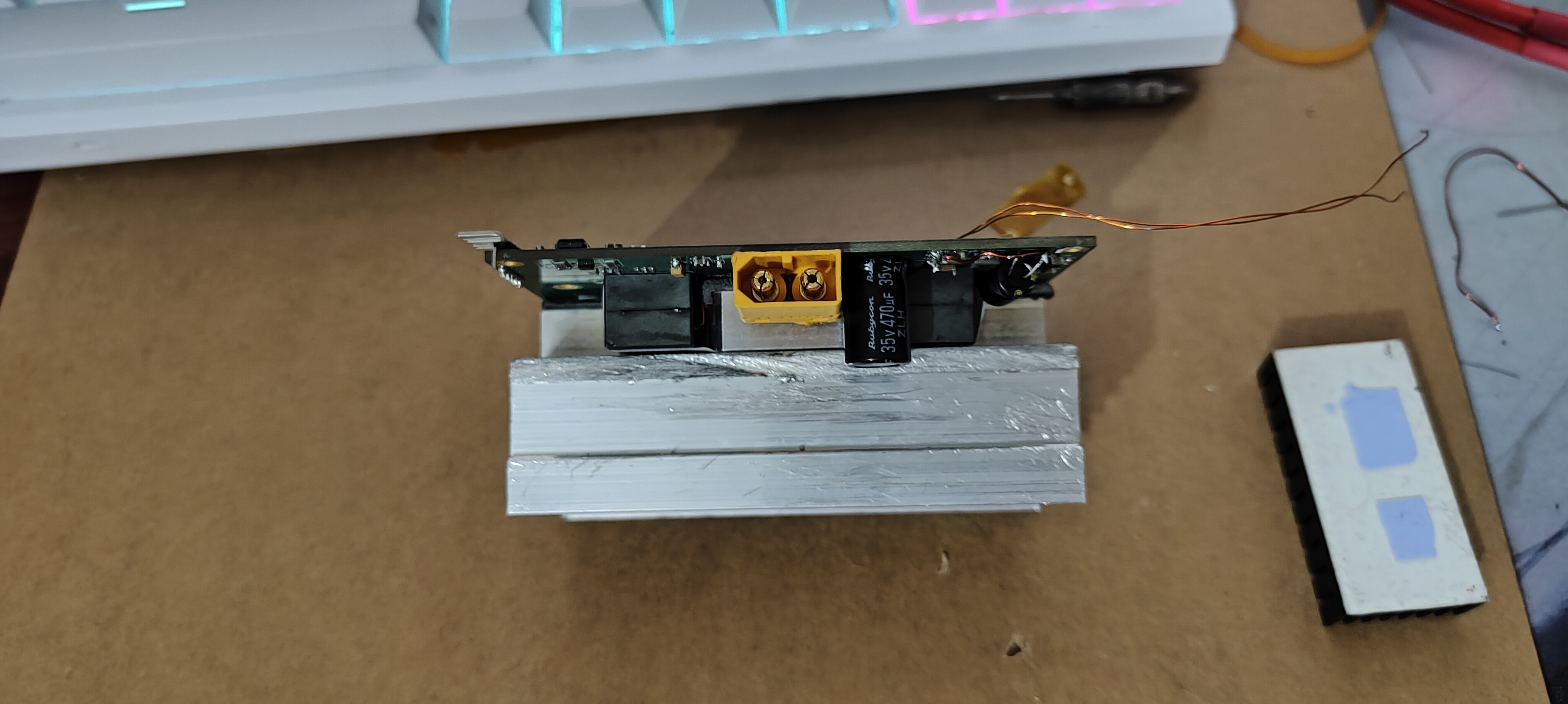
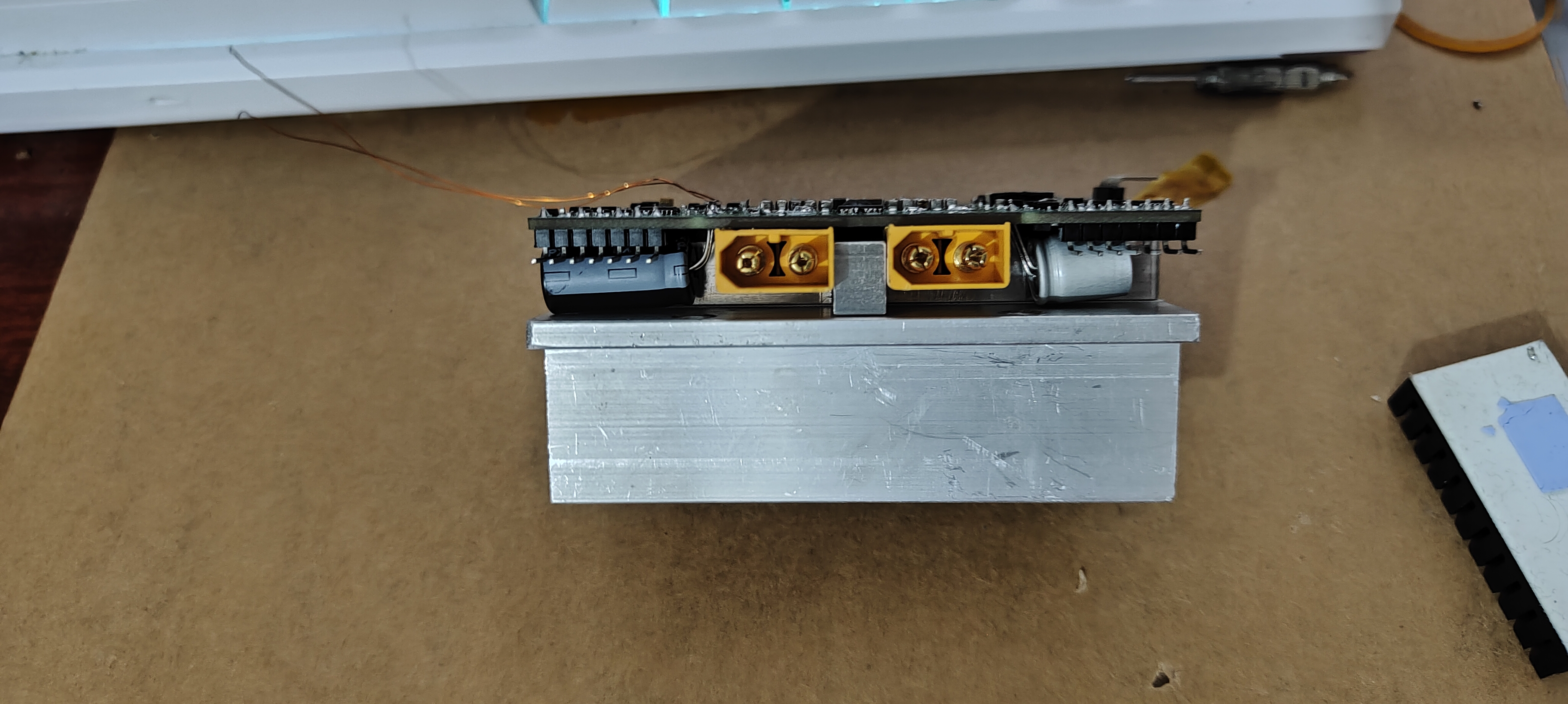
To reduce height, components with a certain height are placed on the back of the board. This leads to a problem: the heatsinks for the MOSFETs and balancing resistors need to be irregularly shaped. For personal use, prototyping irregularly shaped heatsinks is too difficult. Therefore, an aluminum pad is designed to be placed between the components and the heatsinks.

As shown in the diagram, after adding the pad, a fine-toothed heatsink is mounted on the pad. During operation, the inductor's heat cannot be ignored. Making the top surface of the inductor coplanar with the top surface of the heatsink provides additional heat dissipation for the inductor. As shown in the diagram, the inductor and heatsink fit well together.
Hardware Costs
: Many component selections in this project are based on my own component library. Therefore, some component selections are not beneficial for cost optimization, but DIY doesn't require such strict adherence. The main component costs are
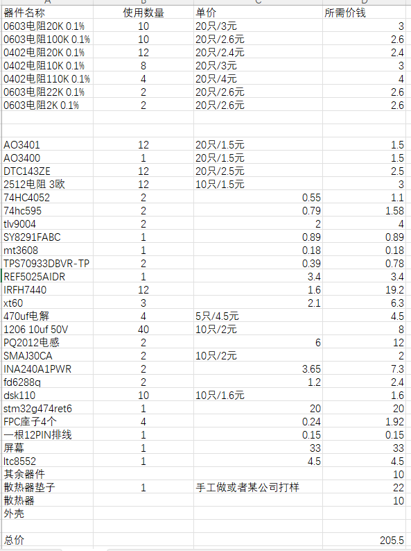
shown in the following figure. The figures represent the prices of components not commonly available on hand; prices may vary, so they are not 100% accurate. There may also be omissions, but these will not be significant, and the total price difference will not be substantial. The cost of the casing is not included because the casing quality for this project is too low; those with the capability are encouraged to design their own casings.
Some software implementation details regarding
buck-boost control:
Generally, when the output is less than the input, the BOOST upper transistor is normally open; when the output is greater than the input, the BUCK upper transistor is normally open. When the output crosses the input voltage, the inverter
half-bridge drive does not have an integrated charge pump, making it impossible to achieve a 100% duty cycle. Therefore, the final result is an approximate 100% duty cycle. Actual measurements
show that the shortest pulse of the FD6288q is over 300 nanoseconds. Therefore, to achieve an approximate 100% duty cycle, the pulse width of the lower transistor is kept at the shortest pulse (500ns in this case), and the frequency is continuously reduced. At this point, the duty cycle of the upper transistor will continuously approach 100%, and there will be an upper limit to the minimum frequency value. Too low a frequency will cause the bootstrap capacitor to lose power too much. This can cause the upper MOSFET to fail to open. My minimum frequency is set to 400Hz, which has been tested and found to be feasible .
In BUCK mode, when a voltage increase is needed, the buck duty cycle is controlled to increase.
When the output voltage approaches the input voltage, the buck frequency is reduced to maximize the duty cycle until the buck frequency reaches its minimum.
If the output voltage is still insufficient at the highest buck duty cycle and further increases are required, the boost duty cycle is controlled
to maintain the upper MOSFET at a low level of 500ns, continuously increasing the boost frequency until the maximum frequency is reached. If a further voltage increase is needed, the duty cycle is increased.
The process of decreasing voltage from a high voltage is the reverse . (
Specific implementation details are provided in the original
text.) MIN_PERIOD 3400
#define MAX_PERIOD 25000
#define MIN_COMP 340
#define MIN_PERIOD_f 3400.0f
#define MAX_PERIOD_f 25000.0f
#define MIN_COMP_f 340.0f
#define MIN_DUTY_MAX_PERIOD (MIN_COMP_f/MAX_PERIOD_f)
#define MAX_DUTY_MAX_PERIOD ((MAX_PERIOD_f - MIN_COMP_f)/MAX_PERIOD_f)
#define MIN_DUTY_MIN_PERIOD (MIN_COMP_f/MIN_PERIOD_f)
#define MAX_DUTY_MIN_PERIOD ((MIN_PERIOD_f - MIN_COMP_f)/MIN_PERIOD_f)
#define min_duty_MAX_PERIOD MIN_DUTY_MAX_PERIOD
#define max_duty_MAX_PERIOD MAX_DUTY_MAX_PERIOD
#define min_duty_MIN_PERIOD MIN_DUTY_MIN_PERIOD
#define max_duty_MIN_PERIOD MAX_DUTY_MIN_PERIOD
#define CHA_BOOST_PERIOD(value) (hhrtim1.Instance->sTimerxRegs[4].PERxR = (value))
#define CHA_BUCK_PERIOD(value) (hhrtim1.Instance->sTimerxRegs[5].PERxR = (value))
#define CHB_BOOST_PERIOD(value) (hhrtim1.Instance->sTimerxRegs[1].PERxR = (value))
#define CHB_BUCK_PERIOD(value) (hhrtim1.Instance->sTimerxRegs[0].PERxR = (value))
#define CHA_BUCK_CCR(value) (hhrtim1.Instance->sTimerxRegs[5].CMP1xR = (value))
#define CHA_BOOST_CCR(value) (hhrtim1.Instance->sTimerxRegs[4].CMP1xR = (value))
#define CHB_BUCK_CCR(value) (hhrtim1.Instance->sTimerxRegs[0].CMP1xR = (value))
#define CHB_BOOST_CCR(value) (hhrtim1.Instance->sTimerxRegs[1].CMP1xR = (value))
uint8_t CHA_PWM_DUTY_SET_BUCK(float duty_cycle)
{
static uint16_t tick = 0;
uint16_t buck_period = 0;
uint16_t buck_comp = 0;
tick++;
if(tick >= 50)
tick = 0;
if(duty_cycle <= min_duty_MAX_PERIOD)
{
if(tick == 10)
{
HAL_GPIO_TogglePin(TEST_IO_GPIO_Port,TEST_IO_Pin);
buck_period = 25000;
buck_comp = 340;
CHA_BUCK_PERIOD(buck_period);
CHA_BUCK_CCR(buck_comp);
}
else
{
buck_period = 25000;
buck_comp = 0;
CHA_BUCK_PERIOD(buck_period);
CHA_BUCK_CCR(buck_comp);
}
return 0;
}
if(duty_cycle < min_duty_MIN_PERIOD && duty_cycle > min_duty_MAX_PERIOD) //Frequency conversion area, small duty cycle
{
buck_comp = MIN_COMP;
buck_period = round(MIN_COMP_f/duty_cycle);
CHA_BUCK_PERIOD(buck_period);
CHA_BUCK_CCR(buck_comp);
last_period = buck_period;
last_comp = buck_comp;
return 0;
}
if(duty_cycle <= max_duty_MIN_PERIOD && duty_cycle >= min_duty_MIN_PERIOD) //Fixed frequency area, medium duty cycle
{
buck_period = (MIN_PERIOD);
buck_comp = round(duty_cycle*MIN_PERIOD_f);
CHA_BUCK_PERIOD(buck_period);
CHA_BUCK_CCR(buck_comp);
last_period = buck_period;
last_comp = buck_comp;
return 0;
}
if(duty_cycle > max_duty_MIN_PERIOD && duty_cycle < max_duty_MAX_PERIOD) // Variable frequency drive (VFD) zone, large duty cycle
{
buck_period = round(MIN_COMP_f/(1 - duty_cycle));
buck_comp = round(buck_period - MIN_COMP);
CHA_BUCK_CCR(buck_comp);
CHA_BUCK_PERIOD(buck_period);
return 0;
}
if(duty_cycle >= max_duty_MAX_PERIOD)
{
buck_period = 25000; // Maximum cycle
if(tick == 20)
{
buck_comp = 25000 - 340;
}
else
{
buck_comp = 25000 + 1; //If 1 is not added, 100% duty cycle cannot be output
}
CHA_BUCK_PERIOD(buck_period);
CHA_BUCK_CCR(buck_comp);
return 0;
}
}
Battery voltage sampling:
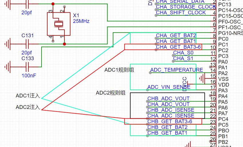
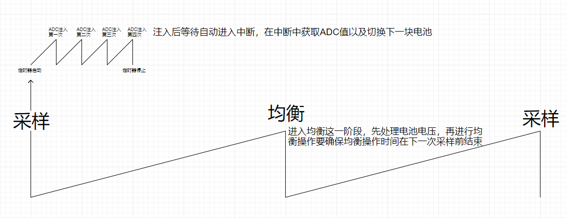
As shown in the figure, the network label with the CHA_GET_ prefix is the battery voltage. The pins of batteries 1 and 2 only need to be read once, while batteries 3-6 need to be read 4 times to obtain the voltage of batteries 3-6 respectively. Each reading requires an operation of the analog switch to switch the battery. The diagram shows the ADC and method used to read the voltage. Battery voltage is read using the ADC's injection group, which is simple, convenient, and fast. Here are some operational details:
The battery voltage is read at a frequency of 50Hz, or once every 20ms.
Because the battery voltage read when the balance switch is open is not the true battery voltage, voltage reading should avoid the balance switch's open time.
A timer is set to interrupt every 10ms. The first interrupt reads the voltage; the second interrupt opens the balance switch (if needed), and the balance switch automatically closes after 6ms (equivalent to a 30% duty cycle). The third interrupt reads the voltage, and so on, staggering the balancing and voltage reading.
Because reading the voltage of batteries 3-6 requires operating an analog switch to switch the batteries, the switching process takes time. Therefore, reading the voltage of batteries 3-6 and switching the batteries must also be staggered. A timer with a 1ms interrupt is used to stagger these processes.
Specific implementation
: #define SWITCH_SERIAL_DATA_HIGH HAL_GPIO_WritePin(SW_SERIAL_DATA_GPIO_Port,SW_SERIAL_DATA_Pin,GPIO_PIN_SET)
#define SWITCH_STORAGE_CLOCK_HIGH HAL_GPIO_WritePin(SW_OUT_CLK_GPIO_Port,SW_OUT_CLK_Pin,GPIO_PIN_SET)
#define SWITCH_SHIFT_CLOCK_HIGH HAL_GPIO_WritePin(SW_SHIFT_CLK_GPIO_Port,SW_SHIFT_CLK_Pin,GPIO_PIN_SET)
#define SWITCH_SERIAL_DATA_LOW HAL_GPIO_WritePin(SW_SERIAL_DATA_GPIO_Port,SW_SERIAL_DATA_Pin,GPIO_PIN_RESET)
#define SWITCH_STORAGE_CLOCK_LOW HAL_GPIO_WritePin(SW_OUT_CLK_GPIO_Port,SW_OUT_CLK_Pin,GPIO_PIN_RESET)
#define SWITCH_SHIFT_CLOCK_LOW HAL_GPIO_WritePin(SW_SHIFT_CLK_GPIO_Port,SW_SHIFT_CLK_Pin,GPIO_PIN_RESET)
//595 driver
uint8_t SW_595_drv(uint8_t reg_data)
{
uint8_t i;
for(i = 0;i< 8;i++)
{
if(0x80 & reg_data)
SWITCH_SERIAL_DATA_HIGH;
else
SWITCH_SERIAL_DATA_LOW;
SWITCH_SHIFT_CLOCK_HIGH;
reg_data = reg_data<<1;
SWITCH_SHIFT_CLOCK_LOW;
}
SWITCH_STORAGE_CLOCK_HIGH;
SWITCH_STORAGE_CLOCK_LOW;
return 1;
}
//Battery switching
uint8_t Switch_Bat(uint8_t Bat_number)
{
uint8_t shift_reg_data;
switch(Bat_number)
{
case 4:shift_reg_data = 0x82; //Battery 4
break;
case 6:shift_reg_data = 0xc3; //Battery 6
break;
case 3:shift_reg_data = 0x41; //Battery 3
break;
case 5:shift_reg_data = 0x00;//Battery 5
break;
default:break;
}
SW_595_drv(shift_reg_data);
return shift_reg_data;
}
void ChargerLoop()
{
static uint8_t stage = 0;
switch(stage)
{
// Sampling
case 0:
HAL_TIM_Base_Start(&htim6);
stage = 1;
break;
// Charging ring calculation, voltage processing, and equalization
case 1:
v_bat_data_process();
HAL_TIM_Base_Start_IT(&htim5);
CHAChargeControl(&CHA_MyChargePara,&CHA_BatBalancePid,&CHA_BatMsg,CHA_power_msg.RunningMode);
CHBChargeControl(&CHB_MyChargePara,&CHB_BatBalancePid,&CHB_BatMsg,CHB_power_msg.RunningMode);
stage = 0;
break;
}
}
void HAL_ADCEx_InjectedConvCpltCallback(ADC_HandleTypeDef* hadc)
{
static uint8_t stage = 0;
if(hadc->Instance == ADC1)
{
CHB_BatMsg.Bat1RawData = HAL_ADCEx_InjectedGetValue(&hadc1, ADC_INJECTED_RANK_4);
CHB_BatMsg.Bat2RawData = HAL_ADCEx_InjectedGetValue(&hadc1, ADC_INJECTED_RANK_3);
CHA_BatMsg.Bat1RawData = HAL_ADCEx_InjectedGetValue(&hadc1, ADC_INJECTED_RANK_2);
CHA_BatMsg.Bat2RawData = HAL_ADCEx_InjectedGetValue(&hadc1, ADC_INJECTED_RANK_1);
}
if(hadc->Instance == ADC2)
{
switch(stage)
{
case 0:
CHA_BatMsg.Bat3RawData = HAL_ADCEx_InjectedGetValue(&hadc2, ADC_INJECTED_RANK_1);
CHB_BatMsg.Bat3RawData = HAL_ADCEx_InjectedGetValue(&hadc2, ADC_INJECTED_RANK_2);
Access_Bat(4);
stage = 1;
;break;
case 1:
CHA_BatMsg.Bat4RawData = HAL_ADCEx_InjectedGetValue(&hadc2, ADC_INJECTED_RANK_1);
CHB_BatMsg.Bat4RawData = HAL_ADCEx_InjectedGetValue(&hadc2, ADC_INJECTED_RANK_2);
Access_Bat(5);
stage = 2;
;break;
case 2:
CHA_BatMsg.Bat5RawData = HAL_ADCEx_InjectedGetValue(&hadc2, ADC_INJECTED_RANK_1);
CHB_BatMsg.Bat5RawData = HAL_ADCEx_InjectedGetValue(&hadc2, ADC_INJECTED_RANK_2);
Access_Bat(6);
stage = 3;
;break;
case 3:
CHA_BatMsg.Bat6RawData = HAL_ADCEx_InjectedGetValue(&hadc2, ADC_INJECTED_RANK_1);
CHB_BatMsg.Bat6RawData = HAL_ADCEx_InjectedGetValue(&hadc2, ADC_INJECTED_RANK_2);
Access_Bat(3);
stage = 0;
HAL_TIM_Base_Stop(&htim6);
__HAL_TIM_SET_COUNTER(&htim6, 0);
stage = 0;
break;
}
}
}
Output shutdown:
Many people may think that output shutdown is simply turning off the PWM, and it is true that turning it off is enough, but there are certain requirements for shutdown. It is best if both bridge arms are turned off at the same time. If they are not turned off at the same time, there is a certain probability of damaging the circuit. Therefore, when shutting down, you cannot just set the timer CCR to zero. You must ensure that both bridge arms are turned off at the same time. You can use a brake or directly disable the PWM.
void PowerStop(uint8_t CHANNEL)
{
if(CHANNEL == CHANNEL_CHA)
{
CHA_OUTPUT_CLOSE();
HAL_HRTIM_WaveformOutputStop(&hhrtim1, HRTIM_OUTPUT_TA1 | HRTIM_OUTPUT_TA2 | HRTIM_OUTPUT_TB1 | HRTIM_OUTPUT_TB2);
__CHA_BUCK_SET_CCR(0);
__CHA_BOOST_SET_CCR(0);
CHA_power_msg.RunningMode = IDLE_MODE;
CHA_MyPowerPara.TargetV = 0;
CHA_MyPowerPara.TargetI = 0;
}
if(CHANNEL == CHANNEL_CHB)
{
CHB_OUTPUT_CLOSE();
HAL_HRTIM_WaveformOutputStop(&hhrtim1, HRTIM_OUTPUT_TE1 | HRTIM_OUTPUT_TE2 | HRTIM_OUTPUT_TF1 | HRTIM_OUTPUT_TF2);
__CHB_BUCK_SET_CCR(0);
__CHB_BOOST_SET_CCR(0);
CHB_power_msg.RunningMode = IDLE_MODE;
CHB_MyPowerPara.TargetV = 0;
CHB_MyPowerPara.TargetI = 0;
}
}
Output Startup
If the circuit hardware includes a reverse connection protection diode, then output startup is straightforward; it's not afraid of reverse current and can be done directly. However, without an output diode, output startup is not so easy; a poorly configured circuit board might smoke, or a damaged preamplifier might explode. If your PID controller is slow, the output voltage will gradually rise from 0 to the battery voltage, resulting in backflow from the battery. Therefore, the output needs to reach the battery voltage instantaneously. This requires feedforward. First, connect the battery, then read the output port voltage before startup. Use this voltage as the feedforward value to calculate the required PWM duty cycle and feed it into the PID's integral stage. This way, the battery voltage can be output instantaneously at startup, seemingly solving the backflow problem. This method works well for batteries with high internal resistance, but it doesn't work well for batteries with low internal resistance, so an improvement is needed. Observing the waveform reveals a significant phase issue in the PWM of the two bridge arms at startup, which is why this method doesn't work well. Once the startup phase issue is resolved, the method works very well. The specific issue is a phase difference between the two PWM controllers at startup. For example, when charging a battery with a voltage higher than the input voltage, the boost PWM might have run for several cycles before the buck PWM starts. This can cause reverse current to flow into the inductor. Alternatively, if the buck PWM starts long before the boost PWM, the inductor may be overcharged
, leading to inductor saturation and potential failure. A relatively correct method is to start the buck PWM first to charge the inductor (a few µs is sufficient) when the input is lower than the output, followed by the boost PWM. This prevents backflow. When the output is lower than the input, both PWMs only need to be started synchronously. Other startup methods include using an output switch that closes only when the output voltage exceeds the battery voltage, also preventing backflow. Another method, though less effective, involves initially using the boost bridge arm as a asynchronous booster, relying on the upper diode for output. Once output current is available, the asynchronous booster switches to a synchronous booster.
void output_set_chb()
{
//CHB
uint32_t primask;
extern float CHB_pid_output_to_controller;
if(CHB_INF.user_wander_mode == POWER_MODE) //User->power mode
{
pid_clear(&CHB_voltage_pid);
pid_clear(&CHB_current_pid);
if(CHBPowerParaChange(CHB_INF.output_voltage,CHB_INF.output_current))
{
CHB_OUTPUT_OPEN();
HAL_HRTIM_WaveformOutputStop(&hhrtim1, HRTIM_OUTPUT_TE1 | HRTIM_OUTPUT_TE2 | HRTIM_OUTPUT_TF1 | HRTIM_OUTPUT_TF2);
HAL_HRTIM_WaveformCounterStop(&hhrtim1, HRTIM_TIMERID_TIMER_E | HRTIM_TIMERID_TIMER_F);
HAL_Delay(10);
primask = __get_PRIMASK();
__disable_irq();
preload(CHANNEL_CHB,CHB_GetOutputVol());
CHB_power_msg.RunningMode = POWER_MODE;
CHB_BUCK_CNT(0);
CHB_BOOST_CNT(0);
HAL_HRTIM_WaveformCounterStart(&hhrtim1, HRTIM_TIMERID_TIMER_E | HRTIM_TIMERID_TIMER_F);
__set_PRIMASK(primask);
__enable_irq();
HAL_HRTIM_WaveformOutputStart(&hhrtim1, HRTIM_OUTPUT_TE1 | HRTIM_OUTPUT_TE2 | HRTIM_OUTPUT_TF1 | HRTIM_OUTPUT_TF2);
}
}
if(CHB_INF.user_wander_mode == CHARGER_MODE) //User->Charging Mode
{
CHB_BatMsg.BatPackVolt = CHB_GetOutputVol();
if(CHBSetChargerPara(CHB_INF.end_voltage,CHB_INF.user_ensured_batnum,CHB_INF.charging_current) == CHARGER_PARA_VALID)
{
if(CHB_INF.use_balance_func == 1)
CHB_BatMsg.start_balance = 1;
else
CHB_BatMsg.start_balance = 0;
pid_clear(&CHB_voltage_pid);
pid_clear(&CHB_current_pid);
pid_clear(&CHB_BatBalancePid);
CHB_pid_output_to_controller = 0;
CHB_power_msg.RunningMode = CHARGER_MODE;
HAL_HRTIM_WaveformCounterStop(&hhrtim1, HRTIM_TIMERID_TIMER_E | HRTIM_TIMERID_TIMER_F);
CHB_BUCK_CNT(0);
CHB_BOOST_CNT(0);
HAL_HRTIM_WaveformOutputStart(&hhrtim1, HRTIM_OUTPUT_TE1 | HRTIM_OUTPUT_TE2 | HRTIM_OUTPUT_TF1 | HRTIM_OUTPUT_TF2);
HAL_Delay(100);
primask = __get_PRIMASK();
__disable_irq();
preload(CHANNEL_CHB,CHB_BatMsg.BatPackVolt); //This is the feedforward, which calculates the required PWM duty cycle based on the output voltage and then fills it into the PID's I-loop.
CHB_PWM_SET(CHB_pid_output_to_controller); // This calculates the period and CCR of the corresponding bridge arm based on the PID output and then fills them into the corresponding registers. // This solves the phase problem of the startup output PWM.
if(CHB_power_msg.BOOST_PERIOD >= CHB_power_msg.BUCK_PERIOD)
{
CHB_BOOST_CNT( CHB_power_msg.BOOST_PERIOD - CHB_power_msg.BOOST_PERIOD % CHB_power_msg.BUCK_PERIOD);
HAL_HRTIM_WaveformCounterStart(&hhrtim1, CHB_TIM_BUCK | CHB_TIM_BOOST);
}
else if(CHB_power_msg.BOOST_PERIOD < CHB_power_msg.BUCK_PERIOD)
{
CHB_BUCK_CNT( CHB_power_msg.BUCK_PERIOD - CHB_power_msg.BUCK_PERIOD%CHB_power_msg.BOOST_PERIOD);
HAL_HRTIM_WaveformCounterStart(&hhrtim1, HRTIM_TIMERID_TIMER_E | HRTIM_TIMERID_TIMER_F);
}
CHB_OUTPUT_OPEN();
__set_PRIMASK(primask);
__enable_irq();
} }
}
The
PWM generator for balancing the battery
uses a 1K frequency timer to generate PWM with a period of 20ms. The first 10ms of this 20ms is used to sample the battery voltage, and only the last 10ms is used to generate PWM to drive the balancing resistor. Therefore, the duty cycle of the balancing resistor is up to 50%, and the maximum average balancing current is battery voltage/3 ohms * 50%. In reality, it is impossible to run such a high duty cycle because the resistor will get very hot if the balancing current is too high, and it is easy to burn out the resistor. This project runs at a maximum duty cycle of 30%.
uint8_t CHA_Bat_control(int8_t bat1_level,int8_t bat2_level,int8_t bat3_level,int8_t bat4_level,int8_t bat5_level,int8_t bat6_level)
{
uint8_t shift_reg_data = CHA_BatMsg.reg_595;
if(bat1_level >= 1)
shift_reg_data |= CHA_BAT1_HIGH;
else
shift_reg_data &= CHA_BAT1_LOW;
if(bat2_level >= 1)
shift_reg_data |= CHA_BAT2_HIGH;
else
shift_reg_data &= CHA_BAT2_LOW;
if(bat3_level >= 1)
shift_reg_data |= CHA_BAT3_HIGH;
else
shift_reg_data &= CHA_BAT3_LOW;
if(bat4_level >= 1)
shift_reg_data |= CHA_BAT4_HIGH;
else
shift_reg_data &= CHA_BAT4_LOW;
if(bat5_level >= 1)
shift_reg_data |= CHA_BAT5_HIGH;
else
shift_reg_data &= CHA_BAT5_LOW;
if(bat6_level >= 1)
shift_reg_data |= CHA_BAT6_HIGH;
else
shift_reg_data &= CHA_BAT6_LOW;
CHA_BatMsg.reg_595 = shift_reg_data;
CHA_595_drv(shift_reg_data);
return shift_reg_data;
}
// This function runs in a 1k timer interrupt. When the equalization flag is enabled, it will run automatically.
void Battery_Balance()
{
static uint8_t tick = 0;
static uint8_t A_tick_duty = 7;
static uint8_t B_tick_duty = 7;
tick++;
uint8_t Bat1Level;
uint8_t Bat2Level;
uint8_t Bat3Level;
uint8_t Bat4Level;
uint8_t Bat5Level;
uint8_t Bat6Level;
uint8_t A_Bat1Level;
uint8_t A_Bat2Level;
uint8_t A_Bat3Level;
uint8_t A_Bat4Level;
uint8_t A_Bat5Level;
uint8_t A_Bat6Level;
if(tick < 2 )
{
if(CHB_BatMsg.data_figured_status == 1 && CHB_BatMsg.start_balance == 1 && CHB_power_msg.RunningMode == CHARGER_MODE)
{
CHB_BatMsg.BalancingVol_status = 1;
if(CHB_BatMsg.bat1_duty > 0)
Bat1Level = 1;
else
Bat1Level = 0;
if(CHB_BatMsg.bat2_duty > 0)
Bat2Level = 1;
else
Bat2Level = 0;
if(CHB_BatMsg.bat3_duty > 0)
Bat3Level = 1;
else
Bat3Level = 0;
if(CHB_BatMsg.bat4_duty > 0)
Bat4Level = 1;
else
Bat4Level = 0;
if(CHB_BatMsg.bat5_duty > 0)
Bat5Level = 1;
else
Bat5Level = 0;
if(CHB_BatMsg.bat6_duty > 0)
Bat6Level = 1;
else
Bat6Level = 0;
CHB_Bat_control(Bat1Level,Bat2Level,Bat3Level,Bat4Level,Bat5Level,Bat6Level);
}
if(CHA_BatMsg.data_figured_status == 1 && CHA_BatMsg.start_balance == 1 && CHA_power_msg.RunningMode == CHARGER_MODE)
{
CHA_BatMsg.BalancingVol_status = 1;
if(CHA_BatMsg.bat1_duty > 0)
A_Bat1Level = 1;
else
A_Bat1Level = 0;
if(CHA_BatMsg.bat2_duty > 0)
A_Bat2Level = 1;
else
A_Bat2Level = 0;
if(CHA_BatMsg.bat3_duty > 0)
A_Bat3Level = 1;
else
A_Bat3Level = 0;
if(CHA_BatMsg.bat4_duty > 0)
A_Bat4Level = 1;
else
A_Bat4Level = 0;
if(CHA_BatMsg.bat5_duty > 0)
A_Bat5Level = 1;
else
A_Bat5Level = 0;
if(CHA_BatMsg.bat6_duty > 0)
A_Bat6Level = 1;
else
A_Bat6Level = 0;
CHA_Bat_control(A_Bat1Level,A_Bat2Level,A_Bat3Level,A_Bat4Level,A_Bat5Level,A_Bat6Level);
}
}
//tick = 7 About 30% duty cycle
if(CHB_BatMsg.max_voltage - CHB_BatMsg.minimum_voltage < 0.004)
B_tick_duty = 2;
else
B_tick_duty = 7;
if(CHA_BatMsg.max_voltage - CHA_BatMsg.minimum_voltage < 0.004)
A_tick_duty = 2;
else
A_tick_duty = 7;
if(tick >= A_tick_duty)
{
CHA_Bat_control(0,0,0,0,0,0);
CHA_BatMsg.data_figured_status = 0;
CHA_BatMsg.BalancingVol_status = 0;
}
if(tick >= B_tick_duty)
{
CHB_Bat_control(0,0,0,0,0,0);
CHB_BatMsg.data_figured_status = 0;
CHB_BatMsg.BalancingVol_status = 0;
}
if(tick >= A_tick_duty && tick >= B_tick_duty)
{
tick = 0;
HAL_TIM_Base_Stop_IT(&htim5);
__HAL_TIM_SET_COUNTER(&htim5, 0);
}
}
Charging
ring To ensure overcharging, constant current followed by constant voltage is insufficient; a charging loop is needed. This loop calculates the appropriate output voltage or current to prevent overcharging of all batteries. Specifically, it uses the battery with the highest voltage as the target voltage (PID), outputs a voltage or current, and then feeds this voltage or current to the power supply's voltage or current PID. In practice, this approach yields better results with higher output voltage. If the current loop is well-designed, the output current will also be fine. My current loop is not ideal, exhibiting some oscillation when the current is too low; therefore, my charging loop outputs voltage.
The pid of the charging ring
float pid_calc_balance(SPID *tspid,BAT_MESSAGE bat_inf,CHARGE_PARA* myChargePara, POWER_MGS power_msg)
{
float sum_P,sum_I,sum_D;
tspid->error = myChargePara->BatEndVoltage - bat_inf.max_voltage;
if(tspid->output < myChargePara->BatEndVoltage*myChargePara->BatNum || tspid->error < 0)
{
tspid->i_error += tspid->error;
}
sum_P = tspid->kp*tspid->error;
sum_I = tspid->ki*tspid->i_error;
sum_D = tspid->kd*(tspid->error - tspid->last_error);
tspid->output = sum_P + sum_I + sum_D;
if(tspid->output > myChargePara->BatEndVoltage*myChargePara->BatNum)
{
tspid->output = myChargePara->BatEndVoltage*myChargePara->BatNum;
tspid->i_error = (tspid->output - sum_P)/tspid->ki;
}
if(tspid->output < bat_inf.BatPackVolt)
{
tspid->output = bat_inf.BatPackVolt;
tspid->output = myChargePara->BatEndVoltage*myChargePara->BatNum;
tspid->i_error = (tspid->output - sum_P)/tspid->ki;
}
return tspid->output;
}
//Charging control, calculated once every 20ms
void CHBChargeControl(CHARGE_PARA* charge_parameter,SPID* balancePID,BAT_MESSAGE *pBatVolt,uint8_t mode)
{
static uint32_t output_control_tick = 0; //20ms per tick
float TotalVoltage = charge_parameter->BatNum*charge_parameter->BatEndVoltage;
float OutputVolt;
float ChargeCurrFromPid;
if(mode == CHARGER_MODE)
{
output_control_tick++;
ChargeCurrFromPid = pid_calc_balance(balancePID,*pBatVolt,charge_parameter,CHB_power_msg);
// OutputCurr = (charge_parameter->ChargeCurrent > ChargeCurrFromPid) ? ChargeCurrFromPid:charge_parameter->ChargeCurrent;
OutputVolt = ChargeCurrFromPid;
CHBPowerParaChange(OutputVolt,charge_parameter->ChargeCurrent);
if(CHB_GetOutputCurr() < 0.1 && output_control_tick > 40 && CHB_power_msg.RunningMode == CHARGER_MODE) // End charging flag
{
turn_off_chb();
output_control_tick = 0;
pBatVolt->start_balance = 0;
MessageBox("","CHB Charge complete");
}
}
else
{
pBatVolt->start_balance = 0;
output_control_tick = 0;
}
}
As you can see from the code, my charging end condition is that the current is less than 0.1A, which is currently fixed and cannot be set manually. It will be changed to be modifiable in future updates.
Regarding calibration
, to ensure a more accurate charging cutoff voltage, multi-stage calibration was implemented, requiring the calibration of 4.2*n (n being an integer from 1 to 6) voltage values. I don't know any effective calibration methods, so this is the best I can do for now. I also found that the non-linearity of the ADC sampled values was quite large, making calibration difficult. However, I've seen other products with the same ADC that achieve high accuracy with only one value requiring calibration; I really don't understand how they do it. Below is the code for calculating the output voltage and current. In calibration mode, it first outputs an approximate value. After calibration, it calculates the voltage value using other methods. The current calculation using this model is quite accurate, requiring only one value to be calibrated. Simultaneously, it detects overcurrent, overvoltage, and backflow; if detected, it immediately shuts down.
//CHB
if(sys_inf.is_in_calib)
{
CHB_power_msg.output_voltage = (CHB_power_msg.Vout_raw_data/RES)*26.6700001;
CHB_power_msg.output_voltage += 0.00179999997*CHB_power_msg.output_voltage*CHB_power_msg.output_voltage - 0.00179999997/10*CHB_power_msg.output_voltage;
CHB_power_msg.Vout_raw_data = 0.05*CHB_Vout_raw_data + 0.95*CHB_Vout_raw_data_last;
}
else
{
if(CHB_power_msg.Vout_raw_data <= MyCalibData.CHB_volt_raw1)
{
CHB_power_msg.output_voltage = CHB_power_msg.Vout_raw_data*(4.2/MyCalibData.CHB_volt_raw1);
}
else if(CHB_power_msg.Vout_raw_data <= MyCalibData.CHB_volt_raw2)
{
CHB_power_msg.output_voltage = (CHB_power_msg.Vout_raw_data - MyCalibData.CHB_volt_raw1)*(4.2/(MyCalibData.CHB_volt_raw2 - MyCalibData.CHB_volt_raw1)) + 4.2;
}
else if(CHB_power_msg.Vout_raw_data <= MyCalibData.CHB_volt_raw3)
{
CHB_power_msg.output_voltage = (CHB_power_msg.Vout_raw_data - MyCalibData.CHB_volt_raw2)*(4.2/(MyCalibData.CHB_volt_raw3 - MyCalibData.CHB_volt_raw2)) + 8.4;
}
else if(CHB_power_msg.Vout_raw_data <= MyCalibData.CHB_volt_raw4)
{
CHB_power_msg.output_voltage = (CHB_power_msg.Vout_raw_data - MyCalibData.CHB_volt_raw3)*(4.2/(MyCalibData.CHB_volt_raw4 - MyCalibData.CHB_volt_raw3)) + 12.6;
}
else if(CHB_power_msg.Vout_raw_data <= MyCalibData.CHB_volt_raw5)
{
CHB_power_msg.output_voltage = (CHB_power_msg.Vout_raw_data - MyCalibData.CHB_volt_raw4)*(4.2/(MyCalibData.CHB_volt_raw5 - MyCalibData.CHB_volt_raw4)) + 16.8;
}
else if(CHB_power_msg.Vout_raw_data <= 65535)
{
CHB_power_msg.output_voltage = (CHB_power_msg.Vout_raw_data - MyCalibData.CHB_volt_raw5)*(4.2/(MyCalibData.CHB_volt_raw6 - MyCalibData.CHB_volt_raw5)) + 21;
}
CHB_power_msg.Vout_raw_data = 0.1*CHB_Vout_raw_data + 0.9*CHB_Vout_raw_data_last;
}
if(CHB_power_msg.output_voltage > CHB_MyPowerPara.TargetV + 1 && CHB_power_msg.RunningMode != IDLE_MODE) //If the output current is greater than 10, overcurrent
{
CHB_power_msg.ERROR_STATUS |= OVER_VOLTAGE;
}
CHB_power_msg.output_current = (CHB_Iout_raw_data/RES*VREF)*POWER_IOUT_GAIN - MyCalibData.CHB_current_zero_offset;
CHB_Vout_raw_data_last = CHB_power_msg.Vout_raw_data;
if((CHB_power_msg.output_current > 15 || CHB_power_msg.output_current < -0.4 ) && CHB_power_msg.RunningMode != IDLE_MODE)
{
CHB_power_msg.ERROR_STATUS |= OVER_CURRENT;
}
`CHB_power_msg.output_current = add_value_and_get_average(&CHB_current_filter, CHB_power_msg.output_current);
if(sys_inf.init_end)
{
CHB_power_msg.output_current += MyCalibData.CHB_CURRENT_BINOMIAL_MODEL*CHB_power_msg.output_current + MyCalibData.CHB_CURRENT_BINOMIAL_MODEL/10.0*powf(CHB_power_msg.output_current,2);
}
}`
Regarding the
UI design
, lvgl was used, and gui-guider was used as the design software. Initially, this project used squareline, but the squareline project files were inexplicably lost, resulting in half of the code being generated by the software and the other half being manually written. Later, squareline was abandoned and gui-guider was used to redesign the UI. It lacks aesthetic appeal, and the final product is indeed not very good-looking, but it has to be used as is. The current UI has four interfaces: the main interface, the parameter input interface, the settings interface, and the keyboard interface.
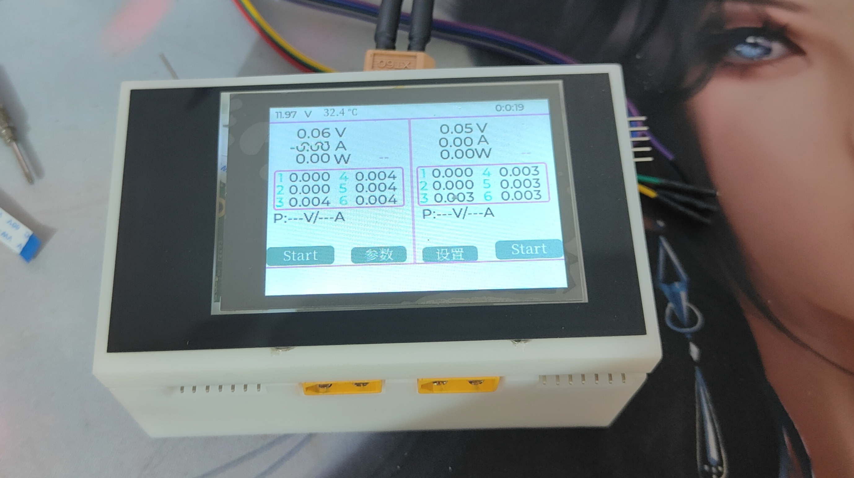
The main interface

displays the input voltage and temperature in the top bar, and the bottom bar now uses MessageBoxes to display information, indicating abnormal states and notifications. Two large boxes represent information for the two channels respectively. The top displays voltage, current, and power, while the smaller box in the middle displays the voltage of batteries 1-6. Below, P: ---V/---A represents parameters, which will change after a parameter is selected. P indicates power supply, and C indicates charger. Clicking the box displaying battery voltage will change the displayed information, changing the battery voltage to battery internal resistance (code not yet written). The parameter information below will then be converted to mAh and Wh values. Regarding the mAh and Wh values, these are for reference only, as they are affected by the accuracy of voltage and current. For charging modes, the mAh value is only valuable when the "Battery Balancing" function is turned off. When "Battery Balancing" is off, the mAh value is the capacity of the cell with the lowest battery capacity in the battery pack.
Parameter Input Interface

The parameter input interface allows you to select the output channel, output mode, and whether to balance the battery. You can also set the voltage, current, and number of battery cells. If you select "auto" for the number of battery cells, the balancing port will automatically detect the number of cells. However, this may be inaccurate if the battery voltage is too low, so check before starting. After confirming the parameters, the number of battery cells will be displayed on the main interface. Verify that everything is correct before starting. If you need to change the voltage, current parameters, or whether to balance the battery during operation, simply enter this interface to set the parameters. Confirmation will take effect.
The settings
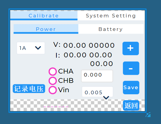
interface contains all system settings and calibration functions. To calibrate the voltage, apply the specified voltage to the output port, select the corresponding channel, record the voltage, and then save. To calibrate the current, select the sixth item in the drop-down menu and then press + or - to adjust. If the adjustment value is too large with a single press, you can select the adjustment step value from the drop-down menu next to the Save button. The calibration steps for battery voltage and current are the same.
The keyboard interface
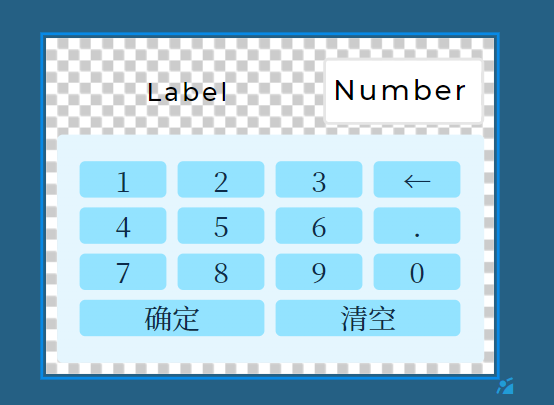
is used for parameter input and consists of a simple numeric keypad.
More features to be developed
support more types of batteries,
dual-channel parallel charging to achieve larger charging current,
preset function,
simple internal resistance measurement,
bidirectional DC-DC
battery discharge
issues.
Due to limited testing conditions, the maximum charging current has not yet been tested; currently, the maximum is 8A. A 12A
current sampling circuit has a wiring problem; the GND network of the differential pair was accidentally covered by the GND copper pour, causing inaccurate sampling. This has been corrected in the circuit, but has not yet been board-tested. The
anti-backflow circuit (to prevent battery insertion in power mode) has not yet been verified. To save time writing code for testing, two parallel 10A Schottky diodes are currently added at the output to prevent backflow, but the efficiency is relatively low.
The current buck-boost circuit control method is the simplest one, with all four transistors working simultaneously, which is less efficient. Single-mode control is used, which is more efficient.
The current loop is not well designed, and there is some oscillation at low current. Regarding the hardware
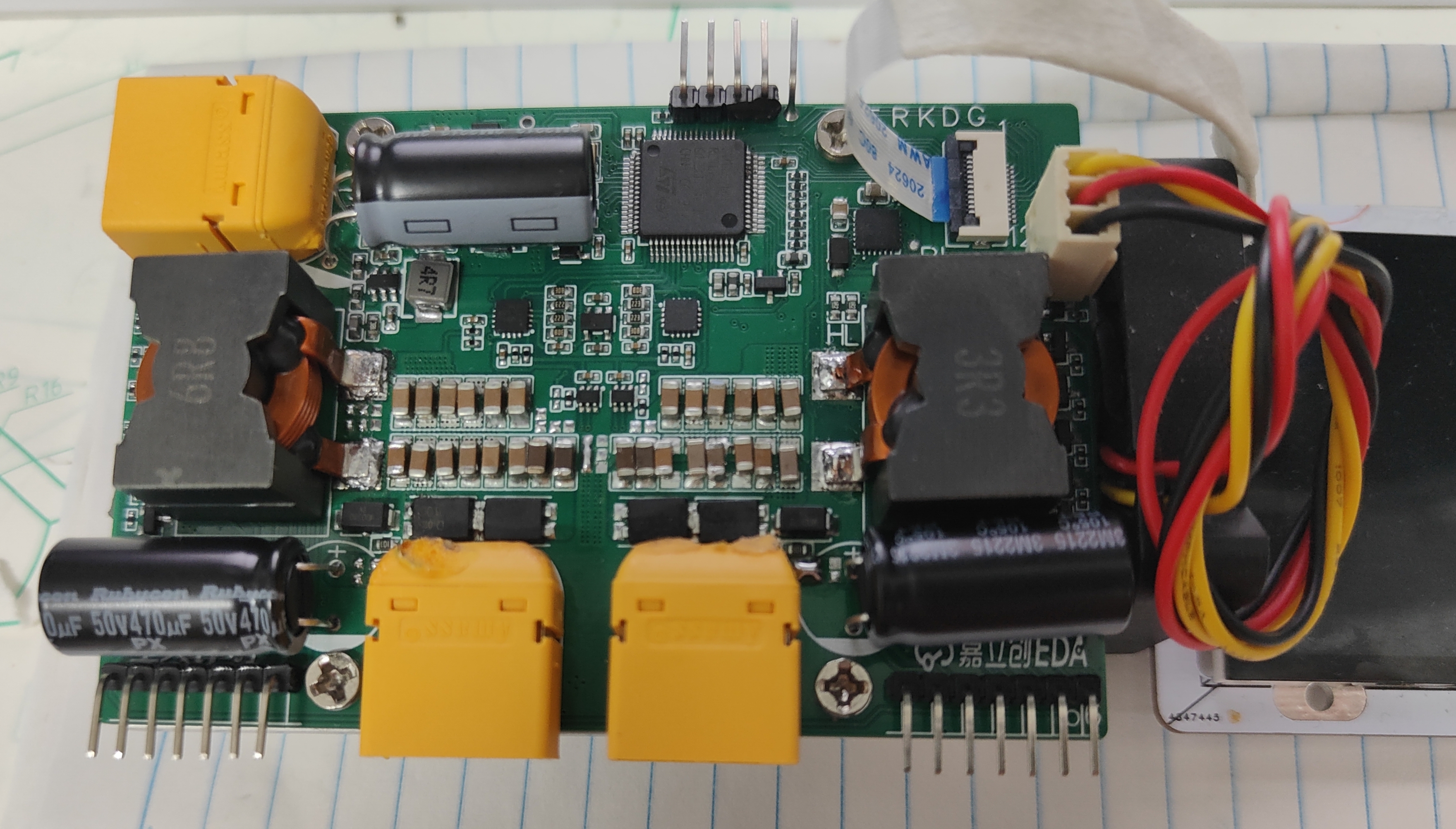
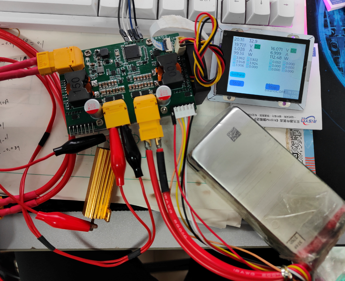
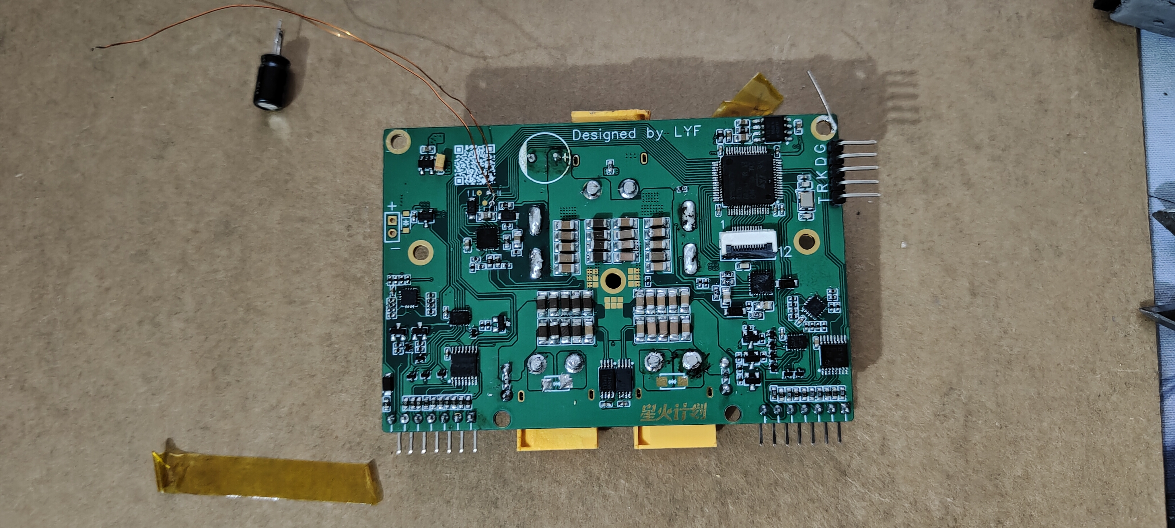
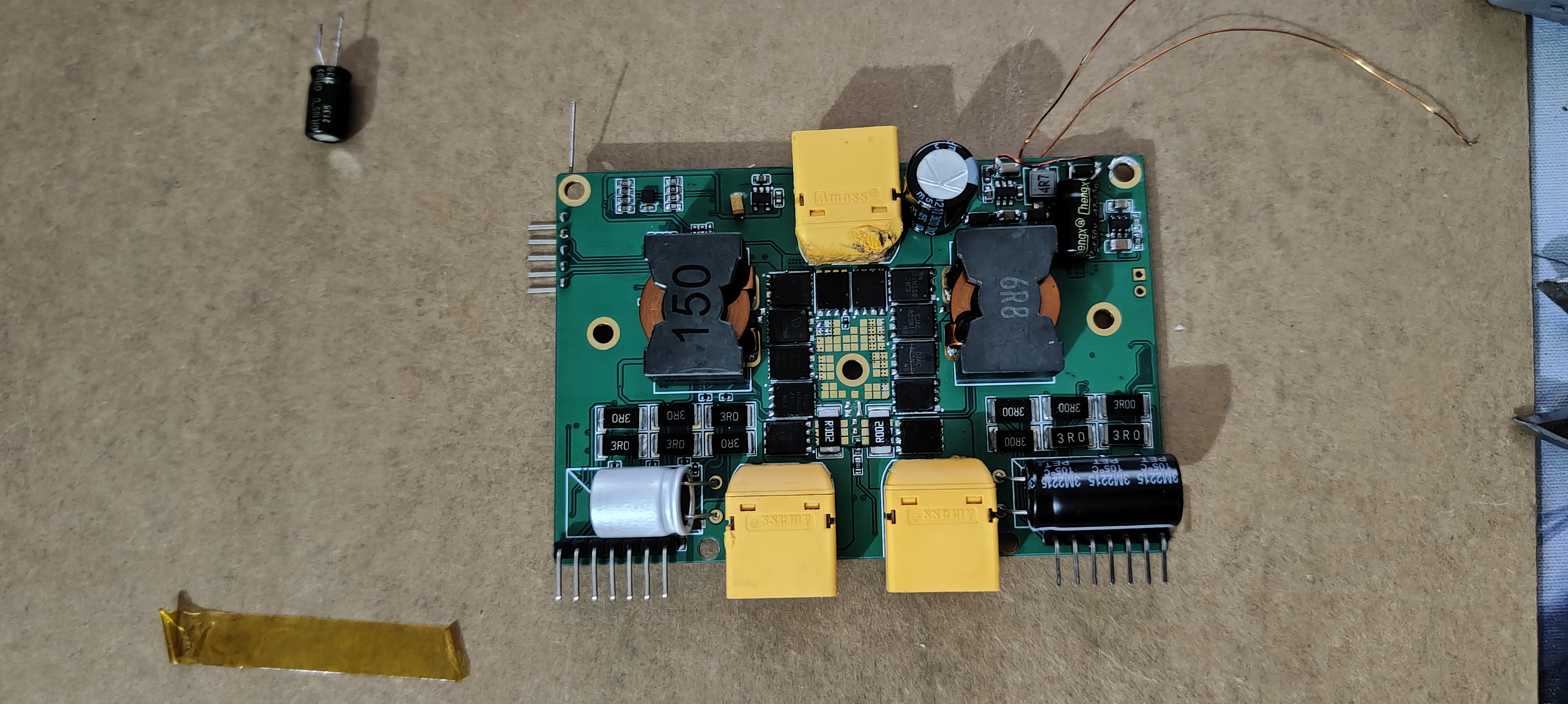
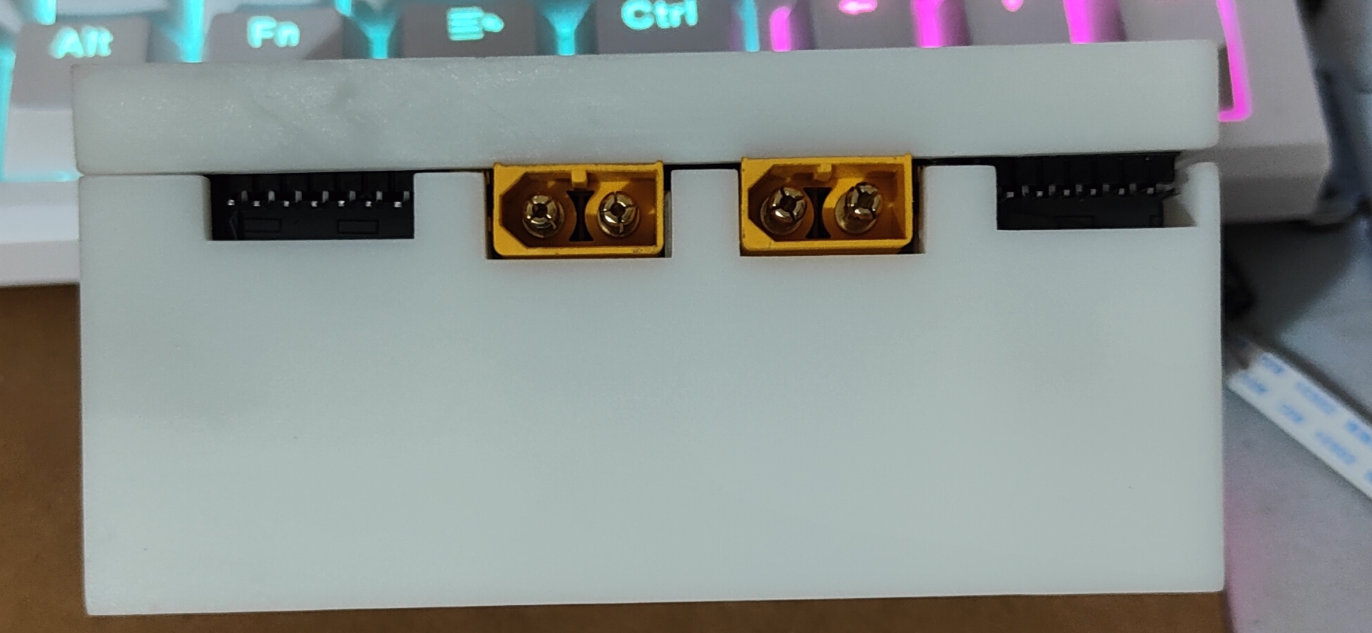
replication: This project uses a lot of QFN packaged chips and FPC sockets. For the soldering of these two devices and the microcontroller, it is recommended to tin them before surface mounting. Specific steps: First, apply solder paste to the pads, heat with a hot air gun, then remove excess solder with a soldering iron. Next, apply a thin layer of flux to the pads, place the components, ensuring the pins are roughly aligned, and finally heat until the solder melts. Use tweezers to gently touch the components and return them to their positions. For the output capacitors in the four-switch buck-boost, the electrolytic capacitors must be carefully aligned with the positive and negative terminals. This is important because one capacitor in my schematic is reversed, and its polarity is not marked on the PCB. Software: I spent a lot of time writing and debugging the project code. Although it's poorly written, I don't want to upload it directly, as this would hinder the project's replication and violate the open-source principle. Therefore, anyone interested in replicating this project or feeling that its hardware or software is lacking can modify and build the PCB themselves. Then, add me on QQ (1911989299) to obtain the source code. I will only provide the source code after the hardware is soldered. Feel free to contact me for assistance with replication; I will answer when I have time. Some images below have changed with the redesign. Front view of the board: This image shows channel A charging a 5s battery; channel B is in power mode . Side panel with an unsuitable heatsink added to the front of the board. Bottom view of the board with thermal pads added to the output ports . Top view of the entire machine. Front view of the entire machine.


 京公网安备 11010802033920号

 PSL12-MH


