Project Description:
This project is an inexpensive, multi-channel function generator based on FPGA. It is an
open-source project
and commercial use is prohibited without the author's permission. Reproduction or citation must credit the original author and include a project link. For other inquiries, please email Defenver@foxmail.com.
Project Functionality
: This function generator implements the following functions:
4-channel analog waveform output, 5MHz bandwidth, 100MHz analog waveform refresh rate, 8-bit output precision (MS9708);
Adjustable 4-channel analog waveform output frequency, refresh rate step up to 1kHz;
Support for negative voltage output, output swing up to ±3V;
Support for outputting various common waveforms,
with adjustable frequency and amplitude; Features a user-friendly interface for quick button operation. Function Generator
Performance Specifications:
Refresh rate 1kHz-100MHz
; Waveform output frequency 1Hz-10MHz
; Output swing up to 8V@1MHz, 4V@10MHz.
4-channel independent synchronous output, adjustable phase.
4-channel selectable dual synchronous clock source output.
Supports output of sine wave, square wave, triangle wave, pulse, DC output and calibration waveform.
Built-in memory automatically reads the waveform status before the last shutdown upon power-on
. Built-in temperature detection page can obtain FPGA operating parameters.
Cost as low as 200 RMB/pcs, further cost reduction can be achieved by using second-hand parts/reducing components.
Note that this function generator does not support USB power supply due to its high operating power (mainly in the DA output section), only DC12V power supply is supported.
[GitHub code repository]
[Bilibili demo video]
Project attributes:
This project is being publicly disclosed for the first time and is my original project. The project has not won any awards in other competitions.
Project progress : USB 3.0
has been successfully verified
, but there is an error in the RF source circuit design. Since it won't affect design specifications,
the current detection circuit can be removed, as it has little practical use.
The temperature detection circuit can also be removed, and instead, the on-chip detection circuit of the FPGA can be used.
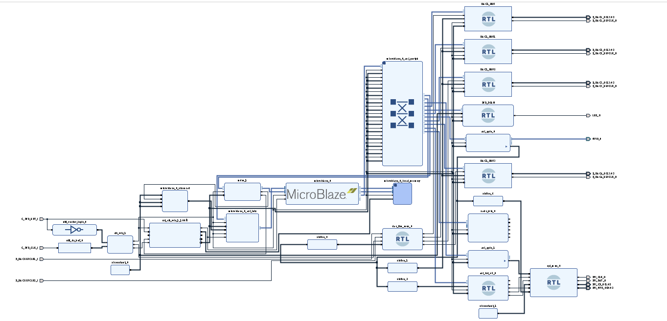
The design principle
is shown in the hardware block diagram below, which will be introduced in sequence.
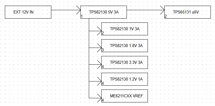
The PCB is a 4-layer board design, smaller than 10*10, and can be made free of charge to further reduce costs. For the

power
supply, due to the high power consumption of the system, a 12V input is used here, and a TPS82130 is used to step down the power rails. To consider the power supply of the op-amps, a TPS65131 is selected as the positive and negative power supply. The specific power tree is as follows.
Each power supply has strict timing requirements, and the numbers in the lower left corner of the block diagram represent the power-on sequence.
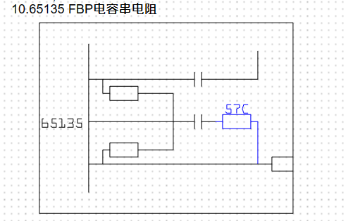
It should be noted that, for unknown reasons, the official circuit of the TPS65131 is incorrect; the correct circuit diagram is shown below. For
the FPGA minimum system
, this design uses the XC7A50T-FTG256 as the main control chip. After actual development, the more affordable XC7A35T can be used as the main control chip.
The minimum system can be found on page two of the schematic, including the following resources:
FPGA core chip, startup circuit,
BPI memory, and
JTAG circuit.
The core principles will not be elaborated here; please refer to the relevant Xilinx manuals.
The DAC and front-end circuit:
The actual DAC model soldered is MS9708, but DAC908 can be used as a substitute. The latter has a significantly higher frequency and higher resolution than MS9708.
The front-end op-amp is ADA4861, a three-channel high-speed op-amp that perfectly meets the design requirements except for not supporting rail-to-rail characteristics. The front-end circuit is shown below.
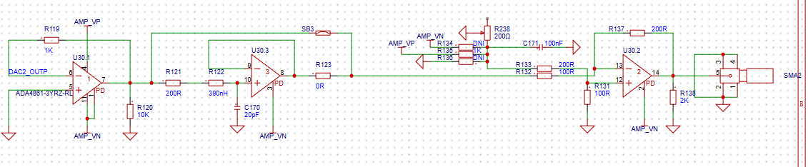
Note that the resistors in the diagram are not actual values; please refer to the notes for actual values.
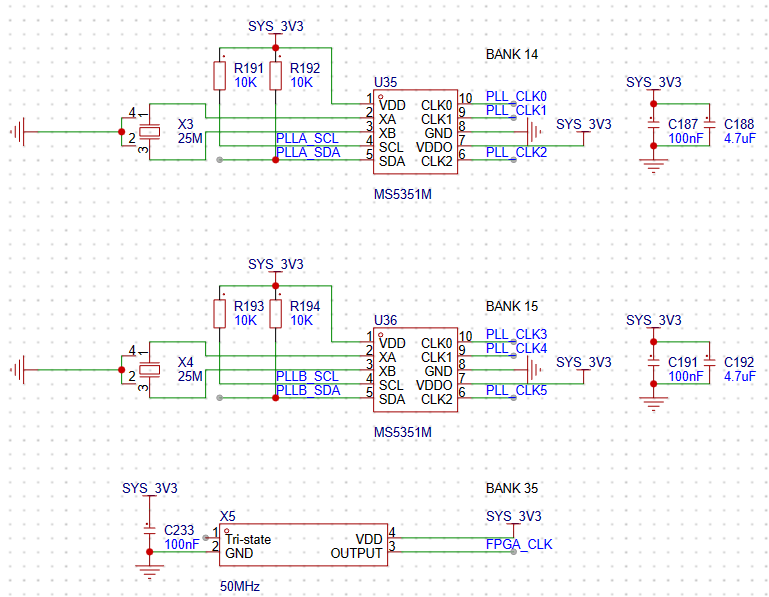
Since the DAC is a current output amplifier, a transimpedance amplifier is needed to convert the current signal to a voltage signal. This is then input to a low-pass filter to remove high-frequency noise. The final amplifier stage implements single-supply to dual-supply conversion and uses an external adjustable resistor for bias fine-tuning. In actual use, the calibration function can be used to fine-tune the waveform bias. The FPGA clock
circuit
has two clock sources: a fixed clock source (50MHz crystal oscillator output) and an adjustable clock source (MS5351 output). The output frequency can be adjusted via IIC.
The USB3 and PLL output circuits
have design errors and will not be discussed further. Users can omit components or delete wiring when replicating the project.
The LCD
screen interface is an 8-pin interface compatible with the Zhongjingyuan interface definition. The actual screen used is

the ST7789 IC, not a screen without CS. Misaligned screw holes are normal.
The software
development platform is Vivado 2020.2; compatibility with other software versions has not been implemented.
This design software is primarily developed using BlockDesigner, using a Microblaze processor to control other peripherals to implement the function generator function. Each module interacts with the processor via the AXI4-Lite bus; the specific implementation principle can be found in RTL.
The program was developed in Vitis, using C language to program the corresponding functions. Since no screen UI library is included, the main function code is slightly cumbersome, but the code related to peripheral control is very simple. Due to my limited teaching ability, I cannot provide a detailed explanation of the program content. Please refer to the code yourself.
Programming only requires compiling the Vitis project, then generating an MCS file in Vivado. Use a W25Q128 memory module, and then use Hardware Manager to burn the corresponding binary file.
Operation:
KEY1-KEY5 control the page, with KEY3 having no function.
KEY1 is for selection; pressing this button selects the cursor.
KEY2 is for the previous option; pressing this button selects the previous option.
KEY3 is for the next option; pressing this button selects the next option.
KEY4 is for exit; pressing this button exits the current selection.
There is a small button between KEY4 and KEY5; this is the reset button.
Design

Considerations:
The front end of the board and the FPGA consume a lot of power during normal operation. Please add heat sinks and use a fan to blow air onto them; otherwise, there is a possibility of overheating and burnout.
Other:
Because the RTL code uses ADI's source code, according to the agreement, this project and its derivative projects must comply with the GPL 2.0 license.


 京公网安备 11010802033920号

 KIA7809AF


