I. Project Introduction
This project involves building a desktop radio in my spare time. The main controller is an ESP32-S3 microcontroller, the FM chip is an RDA5807, and it integrates a CS4344 I2S audio chip for audio playback and an INA199 chip for monitoring the overall operating current. Interaction is achieved using a rotary encoder. Currently implemented functions include:
1. Network clock.
2. FM radio.
3. Weather forecast.
4. Bilibili (Bilibili is a Chinese video sharing website) statistics.
5. Chinese almanac.
6. Backlight adjustment.
7. Timer shutdown.
8. Temperature and humidity display. (Updated May 21, 2023)
Hardware open-source address: https://oshwhub.com/yeshengchengxuyuan/gsm-fm-desktop-multi-function-radio
Software open-source address: https://gitee.com/gsm-fm
Video viewing address: https://www.bilibili.com/video/BV1X24y1J779/?share_source=copy_web&vd_source=d4639a3234ac108fc95036ba5d81874d
If you have any questions during use, you can contact me through the following methods: WeChat: GM8988 QQ: 1063503277 Replica Group: 607741525
Note:
1. Some techniques in this work are from the internet. Due to the inability to find the original author, the source cannot be attributed. If you find any infringement, please contact me for modification.
2. This work is developed, designed, and posted by the author alone. If you find any errors in the work, please feel free to point them out.
II. Hardware Introduction
2.1 ESP32-S3 Circuit
The ESP32-S3 main control circuit is shown in Figure 1. The chip uses internal 8M RAM + external 16M FLAM.
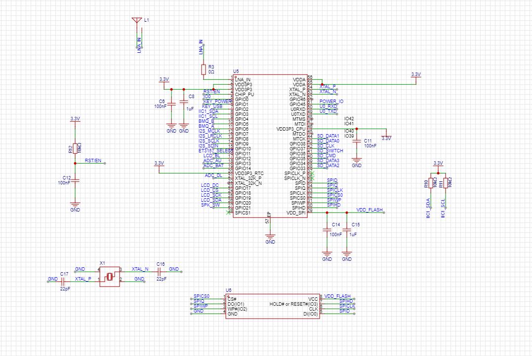
Figure 1 Main Control
2.2 Automatic Power Switching Circuit
The automatic power switching circuit is shown in Figure 2. Q1 is a PMOS transistor, BAT+ is the battery, and 5V is the charger input. When the charger is not connected, Q1 is turned on, and BAT+ flows through Q1 to power VCC. When the charger is connected, Q1 is turned off, and 5V flows through D1 to power VCC.

Figure 2 Automatic Power Switching Circuit
2.3 Software Power On/
Off Circuit The software power on/off circuit is shown in Figure 3. U1 is a 3.3V voltage regulator chip with an enable function, namely pin 3 (CE). A high level input to this pin turns on the output, and a low level input turns off the input. VCC_KEY is the button pin, with one end connected to the power supply (VCC) and the other end connected to the microcontroller pin (KEY_POWER) and the U1 enable pin circuit.
Button Power-On Process: (Without Charger Plug-in) When the button is pressed, VCC flows through VCC_KEY and D4 to give the CE pin a high level, enabling 3.3V output. At this time, the entire system is powered on and the microcontroller starts running. The program first checks the level of the KEY_POWER pin. If the voltage is high, it means that the button power-on control POWER_IO pin outputs a high level to lock the CE pin level. When the button is released, POWER_IO will continue to enable the U1 output because it is still high.
Charging Power-On Process: (Without Button Pressed) When the charger is plugged in, 5V power is supplied through D3 to give the CE pin a high level, enabling 3.3V output and microcontroller operation. The program starts to check the KEY_POWER level. Due to the internal pull-down input, it is detected as low. The program determines that the button is pressed and runs, i.e., charging power-on.
Power-Off Process: After entering the power-off function and confirming power-off, the system pulls down POWER_IO to disable the 3.3V output.
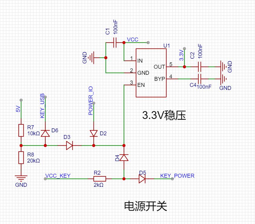
Figure 3 Power-on and Voltage Regulation
2.4 USB to Serial Circuit + Automatic Programming Circuit
The ESP32-S3 supports serial port downloading. Since the computer does not have a TTL serial port interface, a USB to serial chip is needed, as shown in Figure 4. The U7 model is CH340C. This chip supports one USB to serial TTL port and has RTS and DTR control pins. The internal integrated crystal oscillator greatly simplifies the external circuit.
According to the ESP3S3 datasheet, to enter the serial download mode, IO0 needs to be pulled low before power-on. As mentioned above, CH340C has RTS and DTR pins. An automatic reset and IO0 pull-low can be achieved by adding a switch control circuit, as shown in Figure 5. The Q6 chip model is UMH3N. This chip has two transistors and an integrated bias voltage. As shown in the circuit, the RTS and DTR pins of CH340C can be used to achieve automatic program downloading.
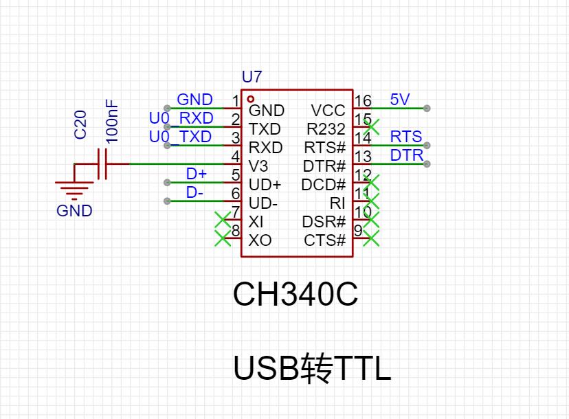
Figure 4 USB to Serial

Circuit Diagram 5 Automatic Download Circuit
2.5 PCB Design
The entire project uses a double-layer PCB, as shown in Figures 6 and 7.
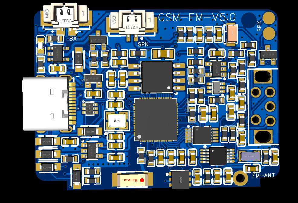
Figure 6 PCB Back Side
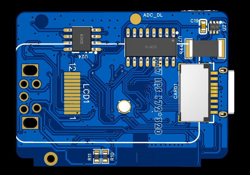
Figure 7 PCB Front Side
III
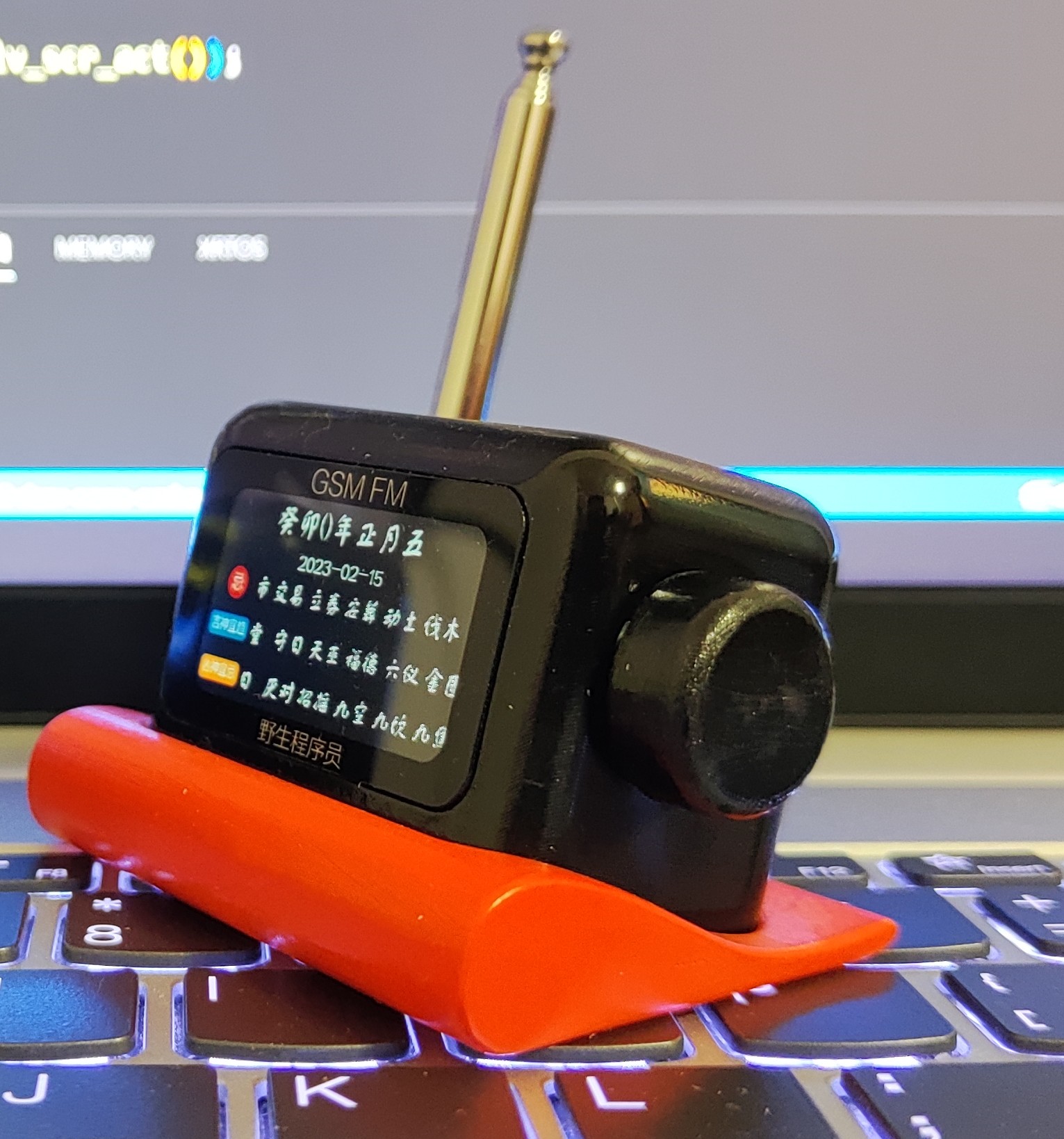
. Housing Design The housing was designed and manufactured using Autodesk Fusion 360.
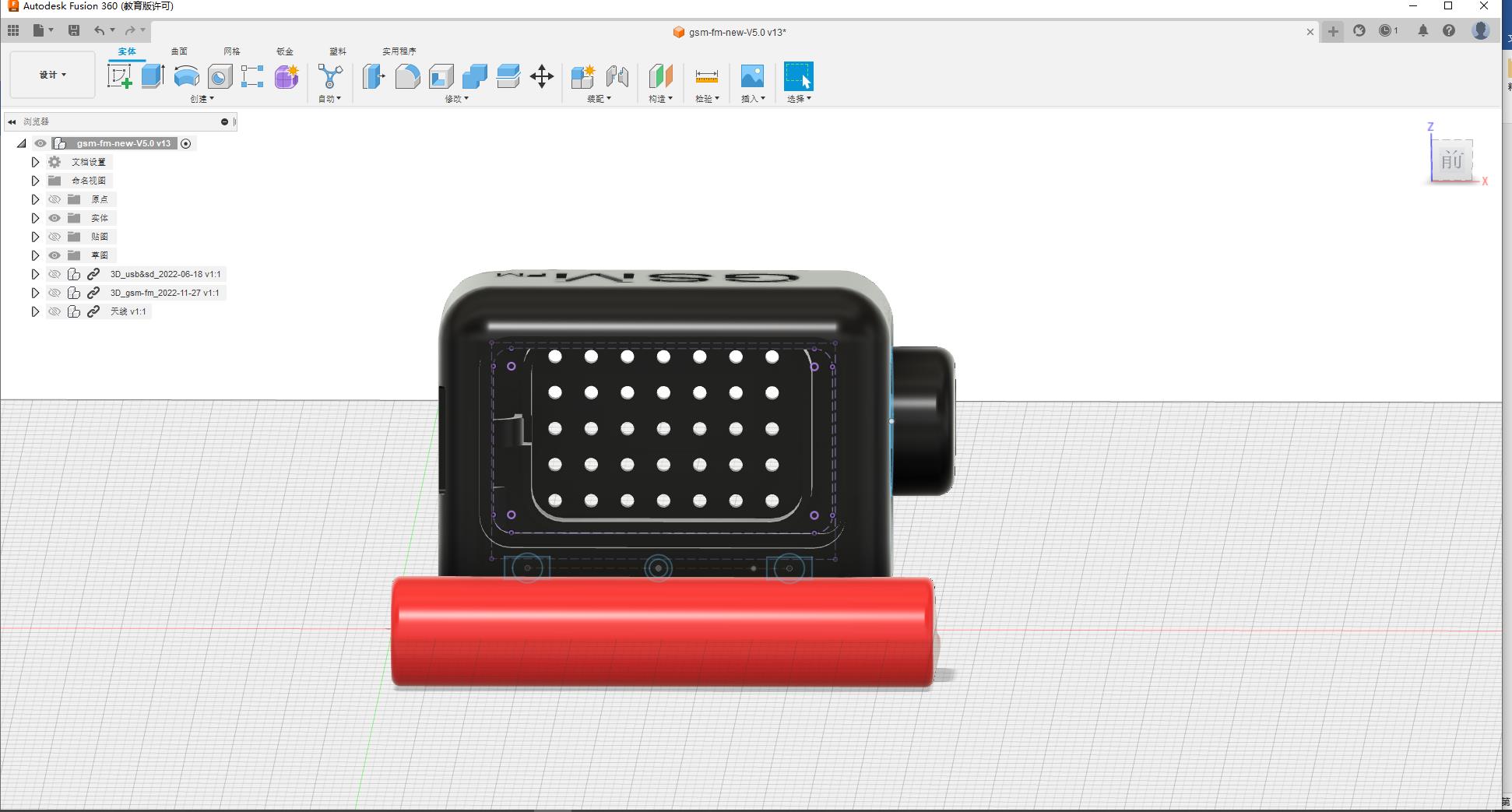
Figure 8 Housing Design
3.1 Screen Installation
The screen is attached to the PCB with double-sided tape. 3.2
PCB Installation
The PCB is clipped into the inner wall groove of the housing and secured with a screw.

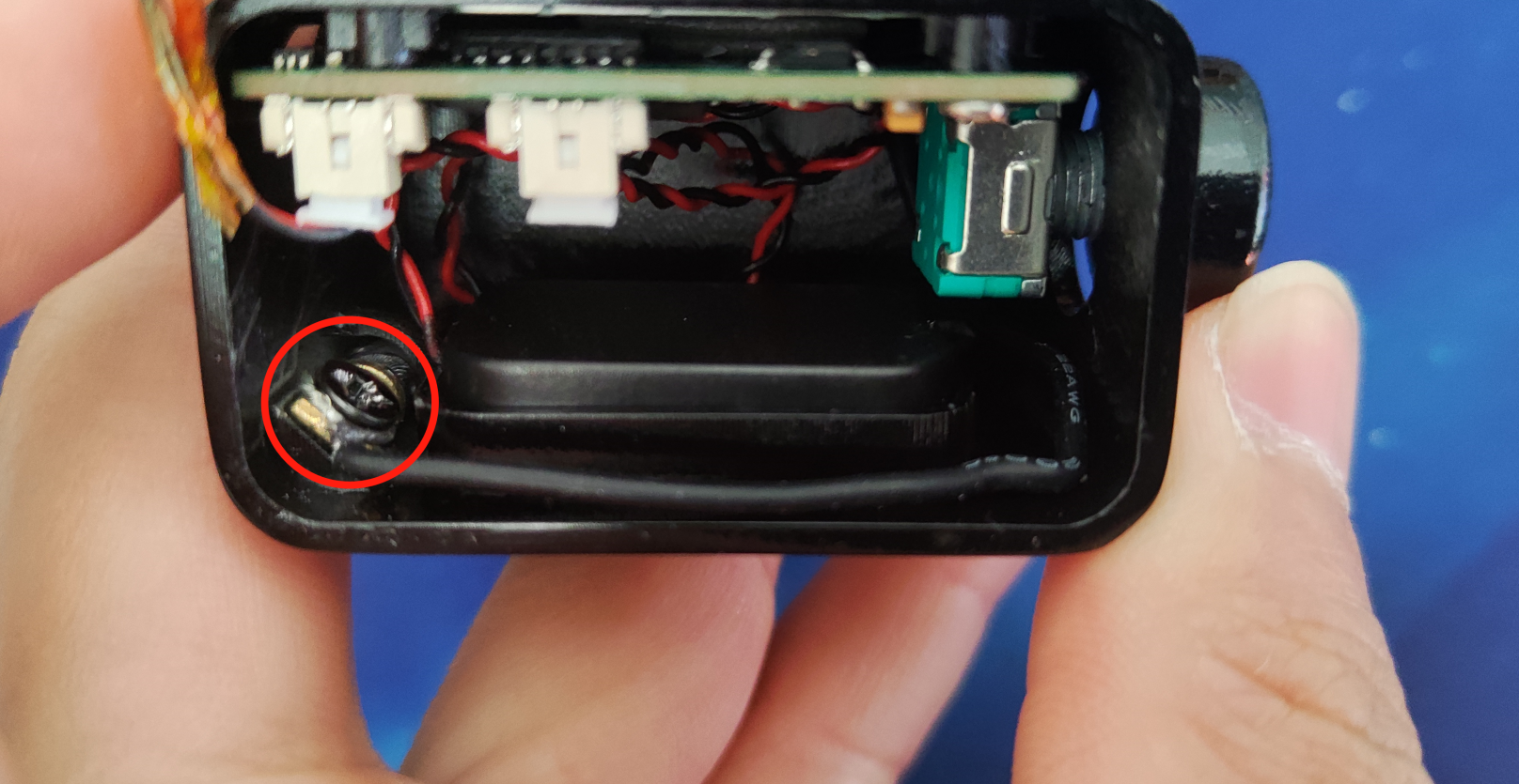
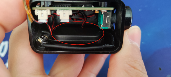
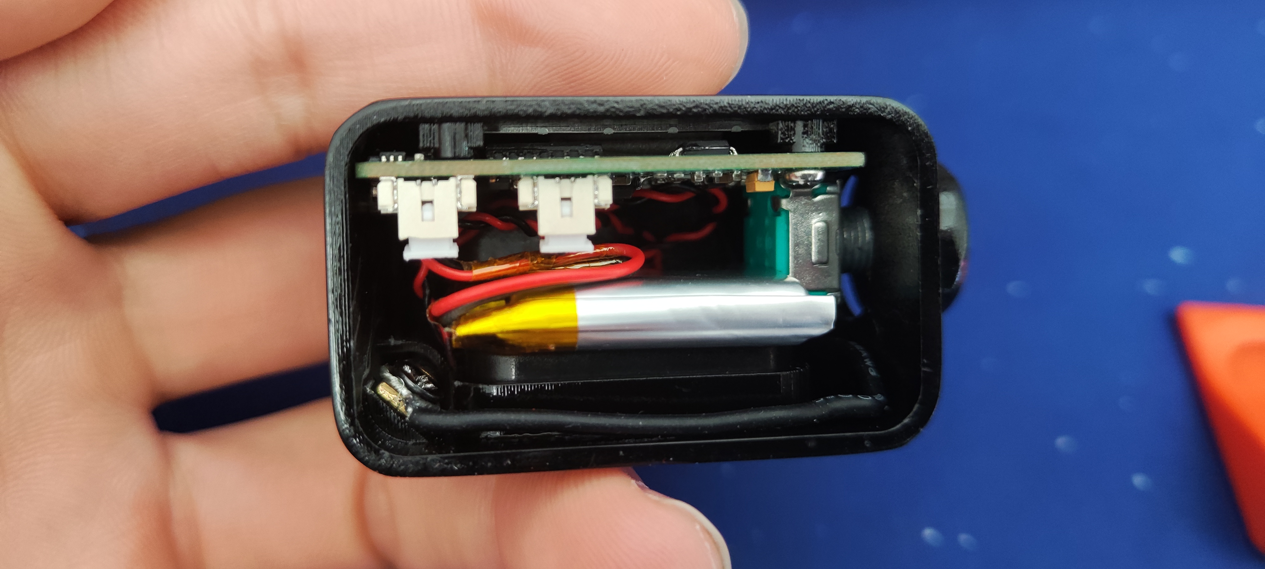
Figure 9 PCB Installation 3.3 Antenna Installation The antenna is inserted into the housing through a slot and the wires are secured to the housing with screws. Figure 10 Antenna Installation 3.4 Speaker Installation The speaker is directly clipped into the housing slot. Figure 11 Speaker Installation 3.5 Battery Installation The battery is placed in the internal empty space. Figure 12 Battery Installation 3.6 Exterior Color Design After designing the housing, it is 3D printed, and then the housing color is changed using spray paint. Figure 13 Exterior Color Matching IV. Software Introduction After the hardware circuit design and soldering are completed, coding can begin. This project uses Espressif's official ESP-IDF5.0. The code will not be fully detailed here. Those interested can search for this project (gsm-fm) on the LCSC open-source hardware platform. The project description contains complete, commented code that you can read yourself. Below are two brief examples: 4.1 Boot Animation The boot animation uses the LVGL GIF library. During development, it played correctly using the VS emulator, but when ported to the ESP32, it kept freezing. Initially, it was thought to be due to the animation being too long, so it was cut into two parts, but this didn't work. After various bug fixes, the problem was finally solved by preloading it into PSRAM. The specific implementation code is as follows: 1. Define two null pointers: char *p_gif1 = NULL;
1. char *p_gif2 = NULL;
2. Load GIF:
load_gif(&p_gif1,"/spiffs/power_on_gif_01.gif");
load_gif(&p_gif2,"/spiffs/power_on_gif_02.gif");
3. Loading process:
bool load_gif(char **p,char *file)
{
bool r_dat = false;
long size=0,r_size=0;
main_debug("Loading file:%s",file);
FILE* f = fopen(file, "r");
if (f != NULL)
{
main_debug("Opened successfully");
size = get_file_size(f);
main_debug("File size:%ld",size);
*p = malloc(size);
if(*p != NULL)
{
main_debug("Memory allocation successful");
r_size = fread(*p, 1, size, f);
if(r_size == size)
{
main_debug("Read successful");
}
r_dat = true;
}else
{
main_debug("Memory allocation failed");
}
fclose(f);
}
return r_dat;
}
4. Use
lv_gif_create_from_data(lvgl_power_on_data.cont_main, p_gif1);
lv_gif_create_from_data(lvgl_power_on_data.cont_main, p_gif2);
5. Release memory after use
free(p_gif1);
free(p_gif2);
4.2 Modify the configuration file
The entire system is configured through the spiffs_image/system/config.json configuration file. The file content is as follows:
{
"wifi":[
{
"name":"name", //wifi name
"password":"pin", //wifi password
"auto connect":"true" //automatic connection (not used yet)
}
],
"system set":[
{
"wifi switch":"on", //wifi switch (not used yet)
"backlight":50, //backlight intensity
"language":0, //language
"bilibili id":"430380301" //Bilibili data ID
}
],
"radio data":[
{
"background":1, //background playback switch
"p1":"89.1", //save channel 1
"p2":"93.1", //save channel 2
"p3":"95.7", //save channel 3
"p4":"102.8", //save channel 4
"p5":"104.8" //save channel 5
}
],
"clock data":[
{
"type":1,// Clock main type (analog/digital)
"style":1 // Clock style
}
]
}


 京公网安备 11010802033920号

 1N5541UR


