Preface:
Before I conceived of making this electronic load (early 2023), I was fascinated by designing fast charging modules. However, testing the output current of these modules required an electronic load.
The common solution was to use a DC power supply, but for my cluttered workbench, adding another power cable was simply unacceptable. Therefore, I decided to create a self-powered solution.
The design focuses on a simple, beginner-friendly, and aesthetically pleasing all-in-one product.
(For PCB prototyping, please use version 2, Board 2)
November 30, 2023: Added some user instructions.
The product manual
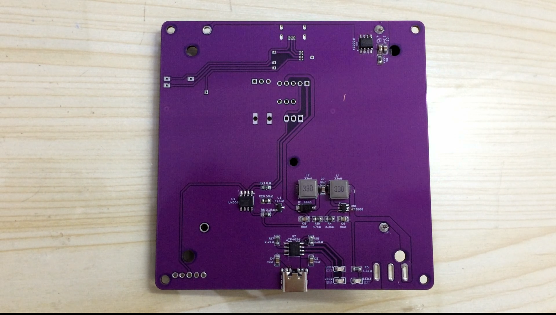
includes lithium battery protection, charging circuitry, fast charging decoy, and constant current control. Each circuit is almost independent and can be soldered as needed, saving costs.
Speaking of cost, a PCB is divided into upper and lower layers for soldering different components, which together form the main body.
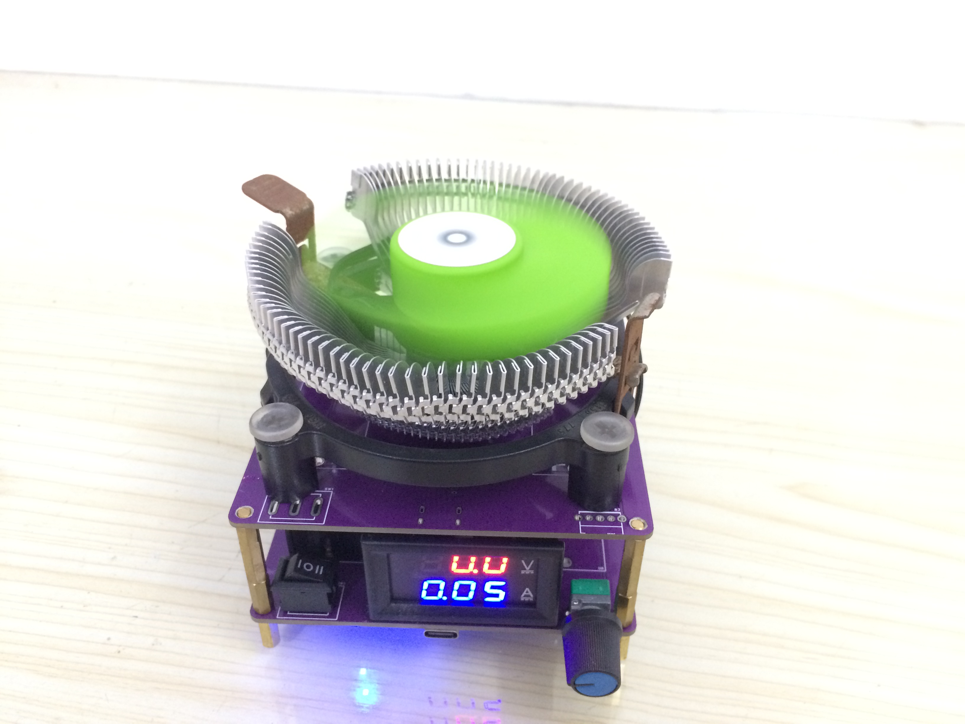
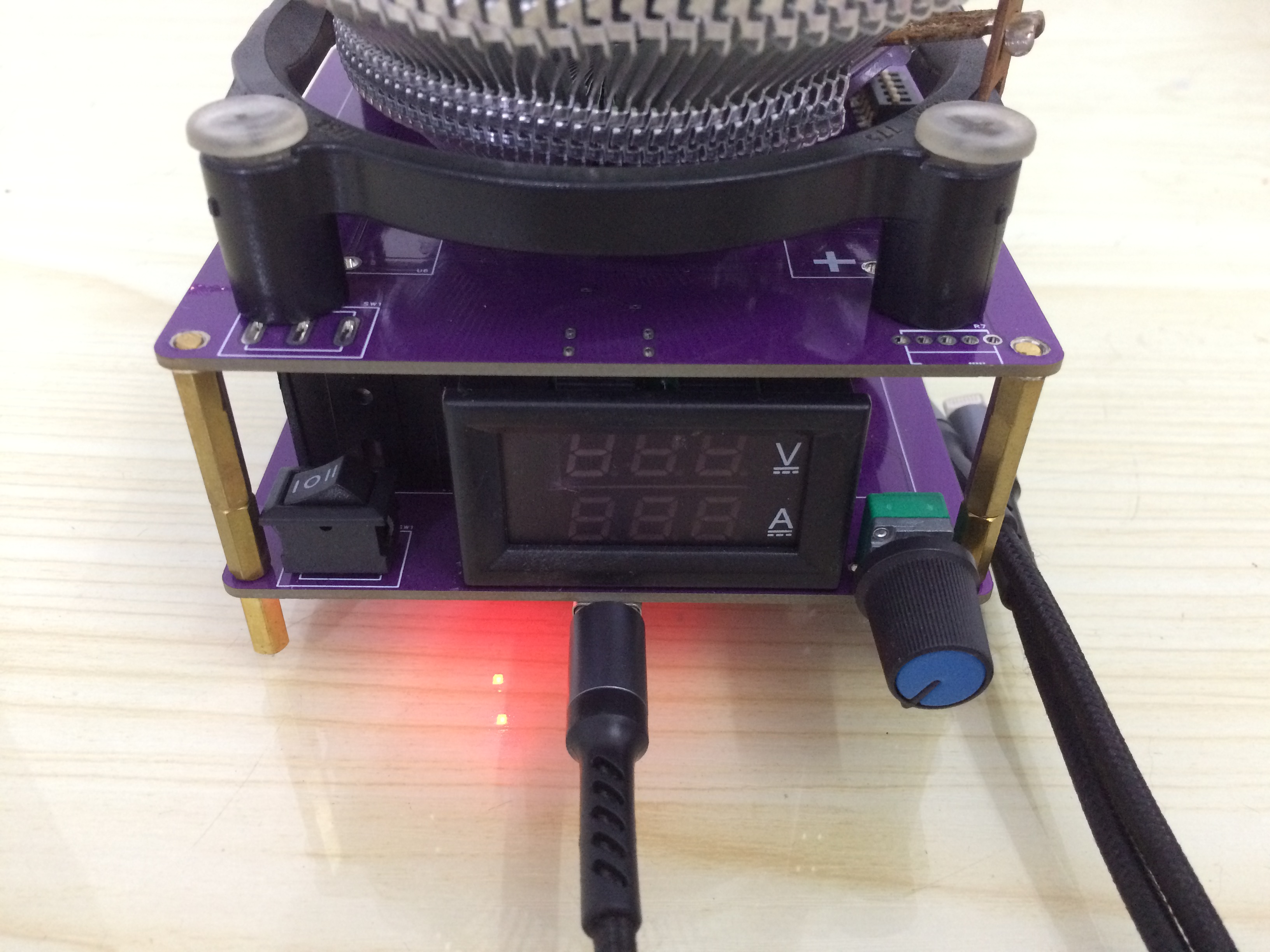
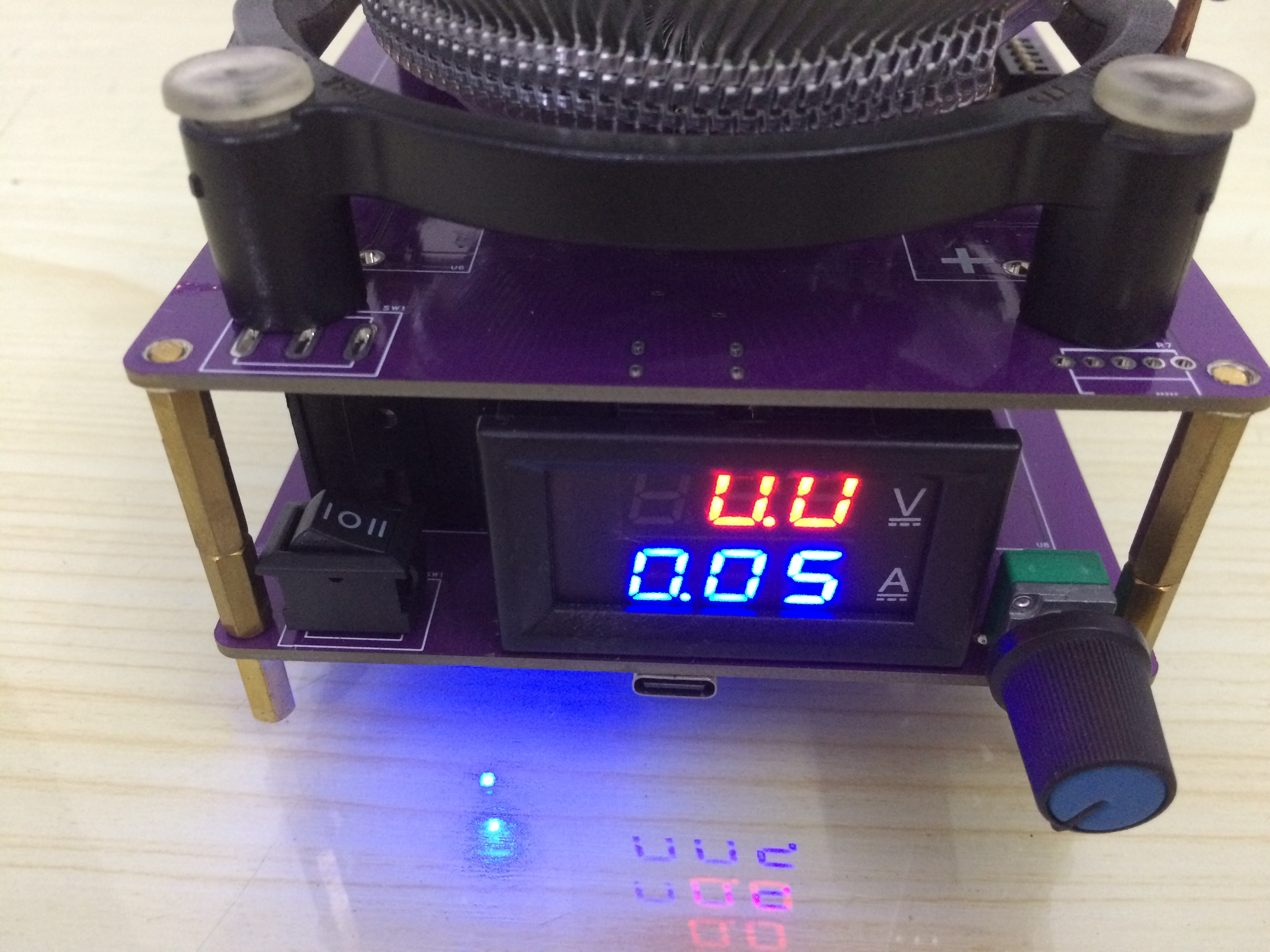
Adding a common dual-display digital voltmeter and ammeter, and a 9.9 RMB CPU fan (shipping included), the cost can be reduced to the minimum.
Input Interface: Type-C, M4 banana plug, supports bare wire connection.
Design test voltage: 0~20V.
Design test current: 0~10A.

Circuit Description:
1. The lithium battery protection circuit
uses the TP4056 chip, a commonly used chip, which will not be discussed in detail.
The power switch is a three-pin, three-position switch, which can completely separate the charging and protection circuits, saving costs by eliminating the need to solder the charging circuit and replacing it with a battery replacement method.

2. The commonly used solution for the lithium battery protection circuit
is a combination of DW01 and 8205A. However, the 8205A is not very easy to solder, so it is replaced with a larger package IP3005A to solve the problem. The design is directly taken from the manual.

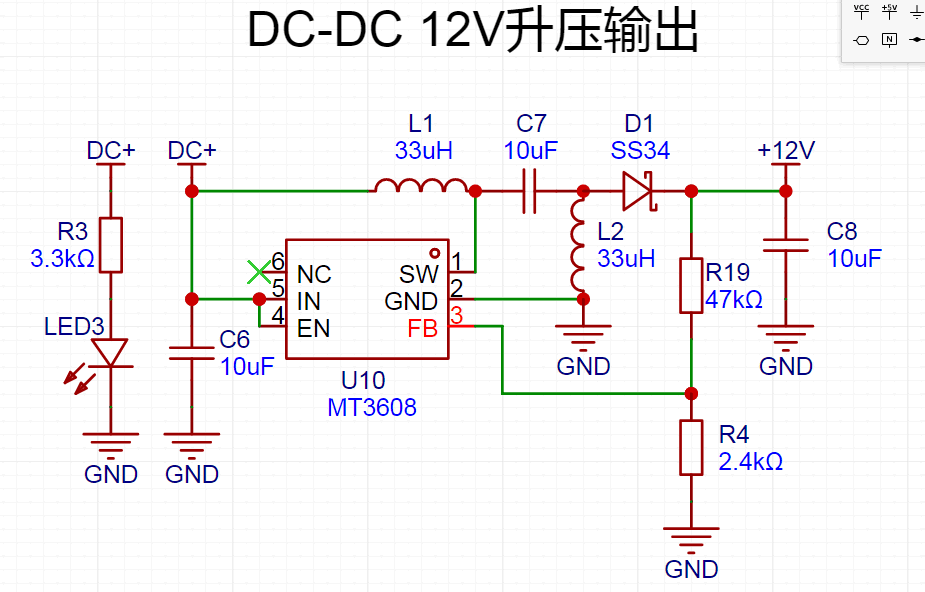
3. Boost power supply circuit:
Since most CPU cooling fans are 12V, and the higher the drive voltage, the lower the on-resistance of the MOSFET, a boost voltage of 12V is chosen.
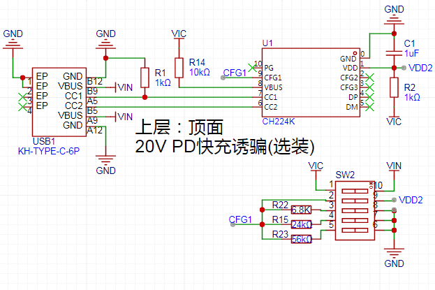
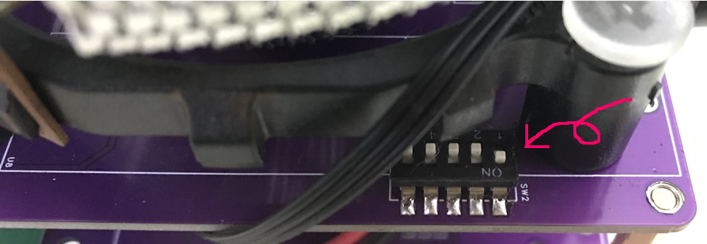
4. Decoy circuit:
This is essential for testing the fast charging module. This circuit is necessary for me personally.
The circuit includes decoys for different voltages: 5V, 9V, 12V, 15V, and 20V, controlled by a DIP switch.
If you don't need these, you can leave them unsoldered; it won't affect the test at all.
5. Constant current control
uses an LM358 to compare the voltage across the sampling resistor R8, thereby controlling the rapid switching of the MOSFET to achieve constant current control.
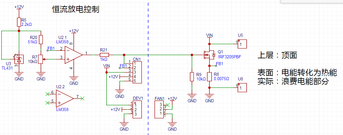
First, a 2.5V reference voltage is generated using a TL431. The ratio of R20 to R7 needs to be selected based on the actual resistance value of the sampling resistor.
For example, the constantan wire resistance of a dual-display voltmeter/ammeter is 7.5 milliohms, and the maximum current measured by the ammeter is 10A.
Therefore, the maximum voltage at the network tag point FB1 is 75mV; in other words, the highest voltage at the voltage divider point of R7 is 75mV.
Since R7 is an adjustable potentiometer, it is generally not replaced, so only the resistance of R20 needs to be changed.
Voltage = 2.5V * (10K/R20 + 10K).
According to the formula, R20 is approximately 300K, but my voltmeter is slightly different, using 51K. Please be aware of this.
Actually, the voltage divider point here is only to limit the maximum constant current, preventing excessive discharge current and subsequent smoke.
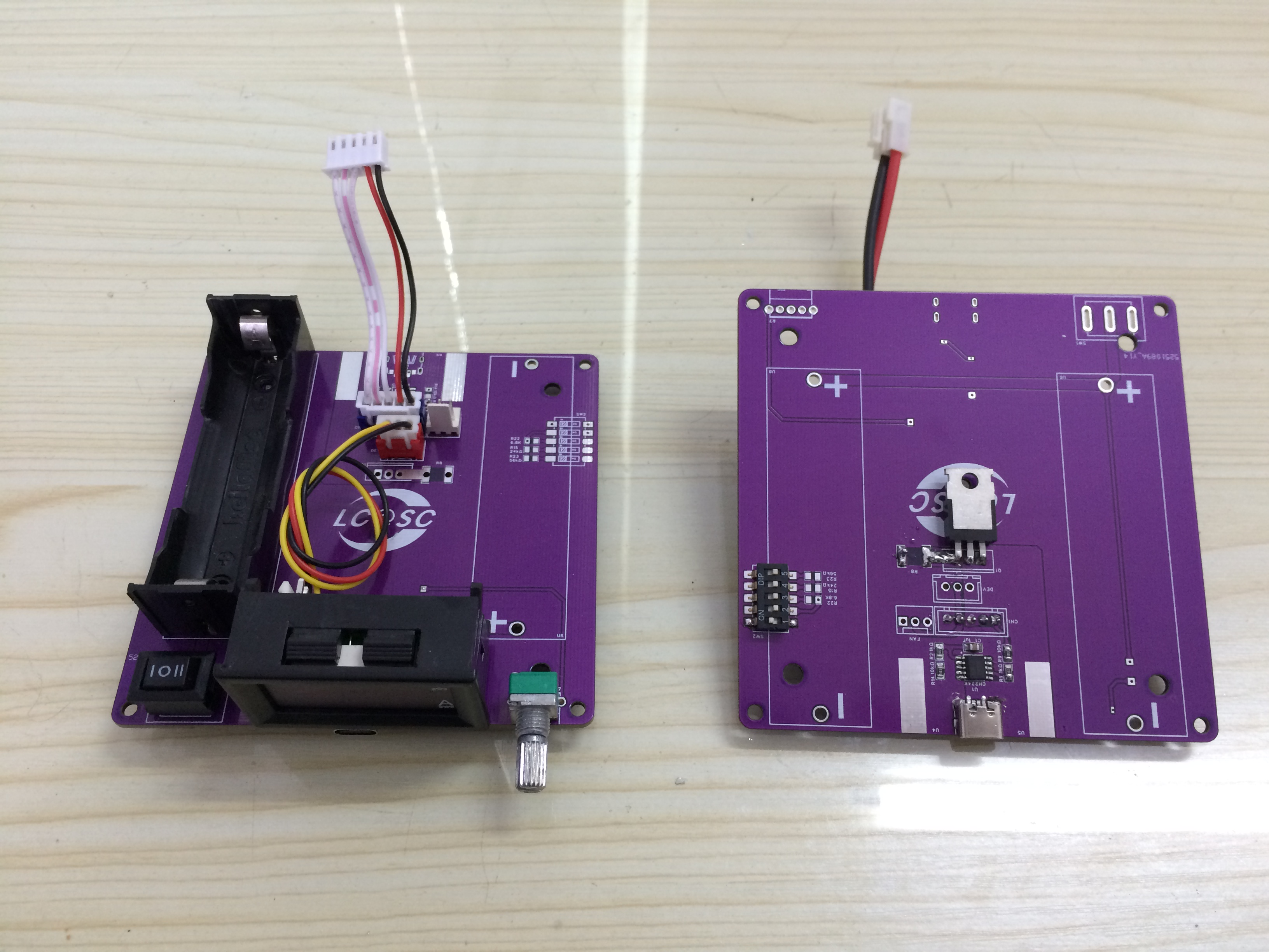
Crucially, solder
the four circuit components on the bottom of the lower PCB: lithium battery protection, charging, boost, and constant current control.
Solder the switch, battery holder, and potentiometer on the top of the lower PCB.
Do not connect the three-pronged three-position switch initially; this is for easy power-on testing of each component. In fact, as long as the soldering is correct, there will be no smoke.
Then solder the components on the top of the lower and upper layers, including the wiring for the digital display voltmeter and ammeter.
The upper MOSFET uses an inverted design, with the heatsink facing upwards for contact with the heatsink. Align the holes on the heatsink with the holes on the PCB.
The competition logo is also displayed here.
For the upper and lower layer wiring connections, the power supply interfaces for the voltmeter and ammeter, and the CPU fan power interface are generally soldered on the lower layer.
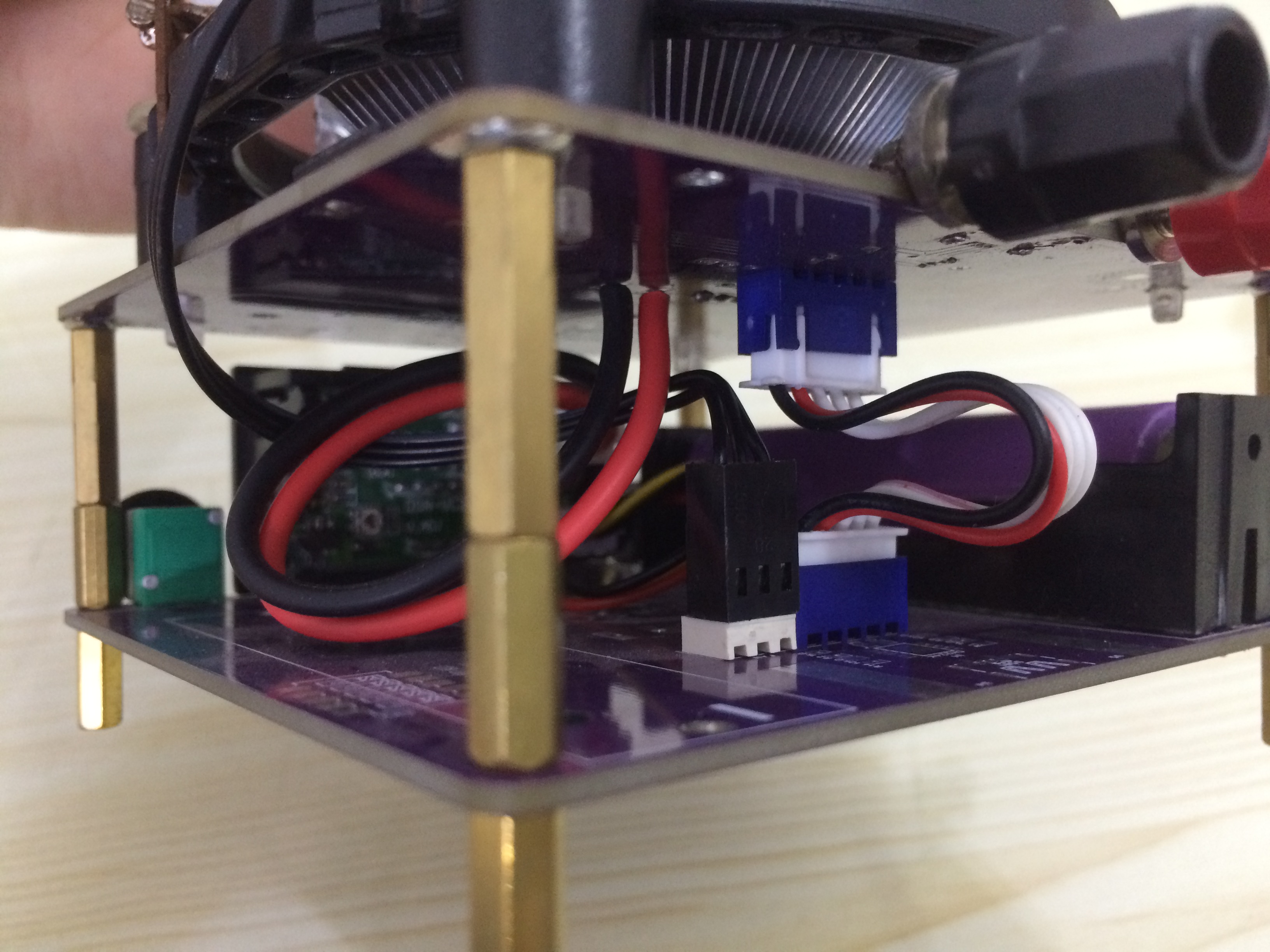
The

upper and lower PCBs are connected by copper pillars:
M3x12+6 (two sections); M3x18+6 (one section) .
If budget is limited, use a regular nut for the top;
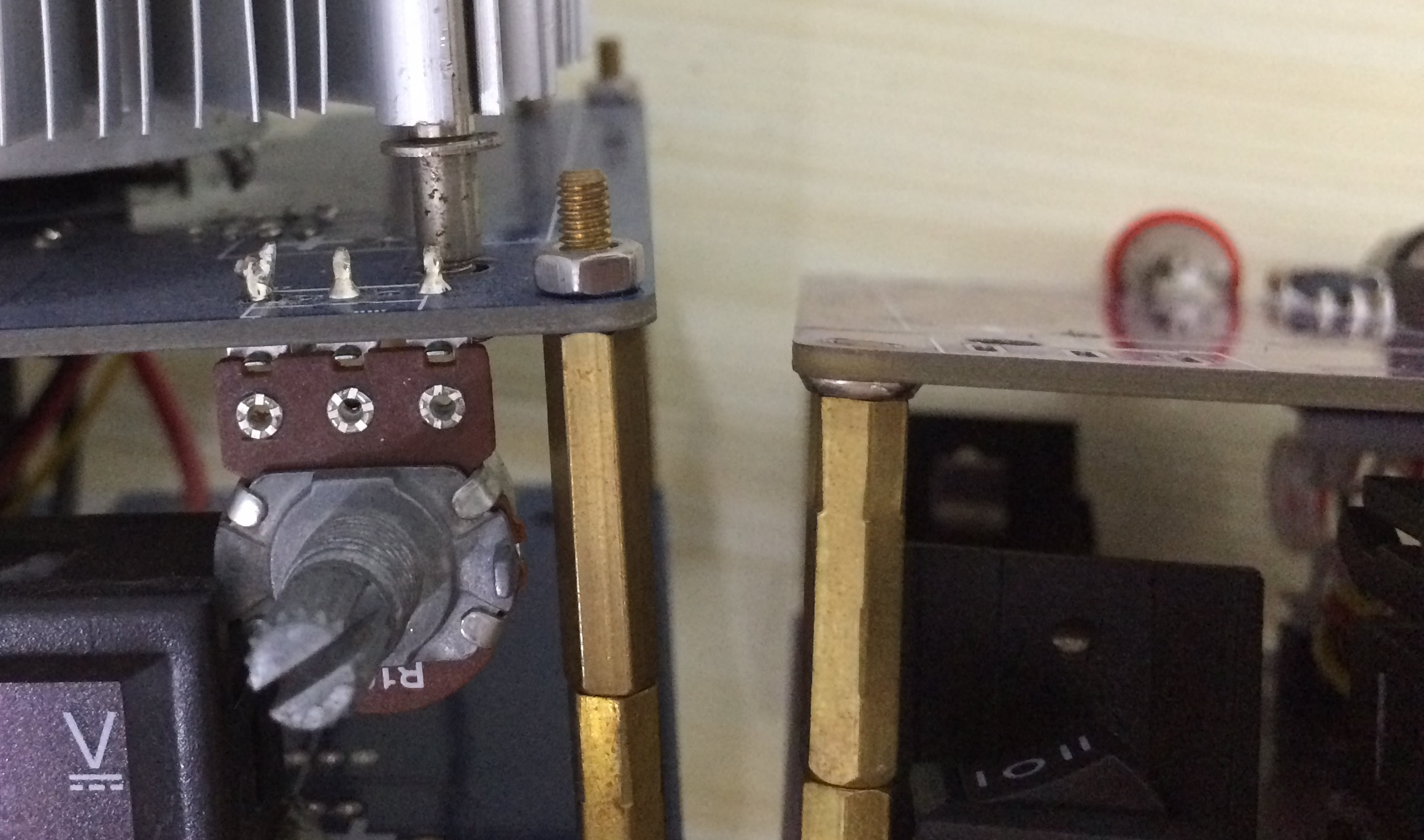
otherwise, use a surface-mount nut for a neater look. The four holes on the outer side of the upper layer are for mounting the CPU fan; older 775-pin fans or the more common dual-purpose fans can be installed.

Basic usage:
A three-prong, three-position switch. From left to right, the three positions correspond to [Charging], [Neutral]
, and [Power Supply]. [Neutral] completely disconnects the lithium battery from other circuits, preventing unnecessary power loss.
When turned left, the lithium battery connects to the charging circuit and can be charged.
When turned right, the lithium battery connects to the boost circuit, equivalent to a regular power switch, entering the working state.
The potentiometer is used to adjust the constant current; the maximum discharge current is set by changing the R20 resistor, as mentioned above.
The CH224K fast-charging decoy chip has a withstand voltage of around 24V. When not using the decoy, disconnect the chip's power supply as much as possible. Only turn the DIP switch to ON when needed.

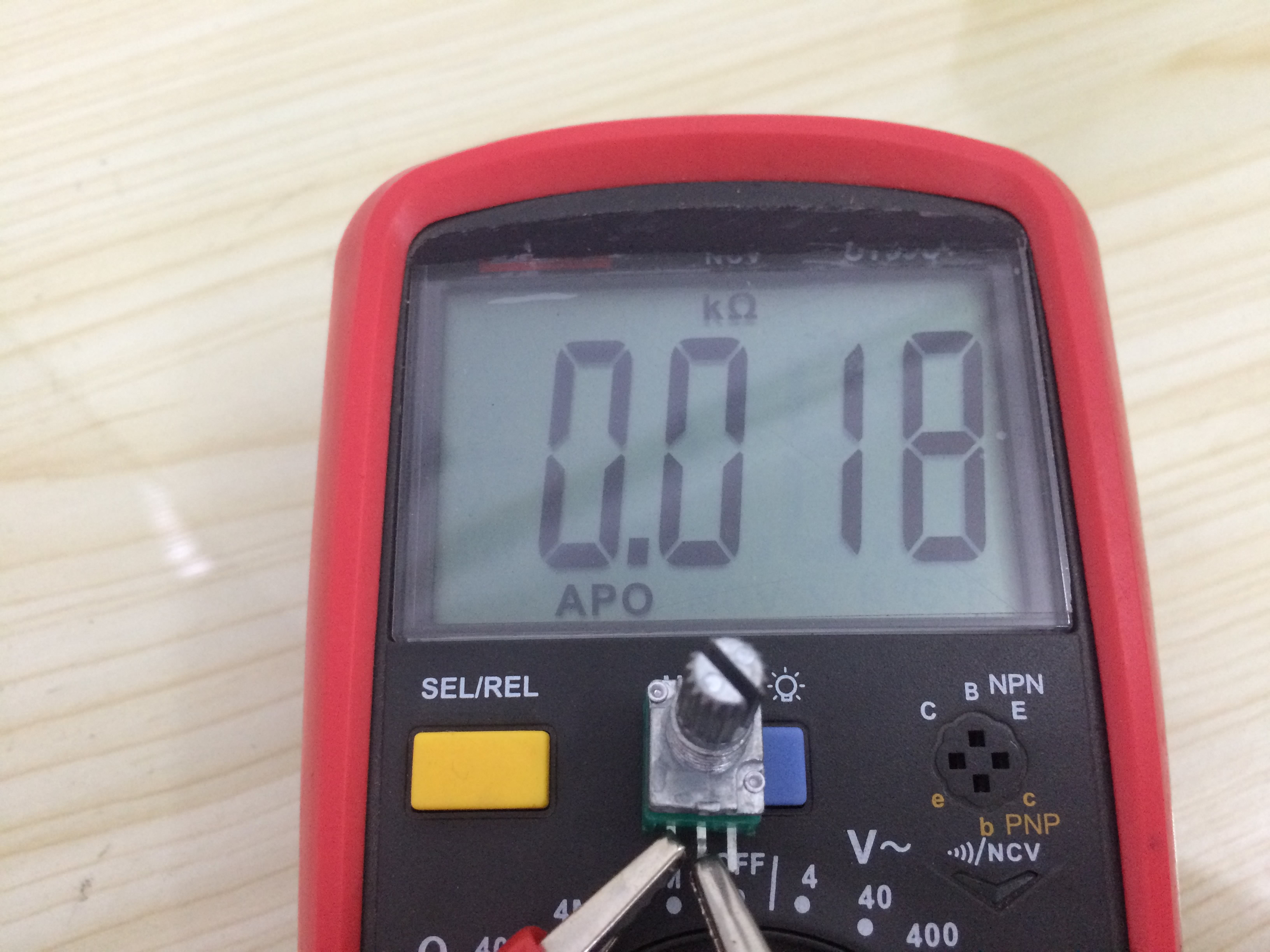
A crucial detail during assembly is to always measure the minimum resistance of the potentiometer before soldering to ensure it returns to zero.
This resistance directly affects the minimum constant current control value after power-on. A high-quality potentiometer achieves 0.07A, while a lower-quality one might reach 0.7A. This can be ignored if requirements are not high.
The video below demonstrates one example using a low-quality potentiometer.
Quick Q&A from "100,000 Whys"
: 1. What is the approximate usage time?
> Generally, one battery is sufficient for short tests. Two battery packs can be installed to increase usage time.
2. Can it test voltages above 20V?
> Replacing the MOSFET with a higher withstand voltage will suffice.
3. Can the test current exceed 10A?
Ammeters with current greater than 10A require a shunt, which takes up a lot of space and is difficult to fit inside.
A solution is to connect several sampling resistors in parallel on the PCB. However, it's necessary to calculate the equivalent resistance value to enhance the PCB's current-carrying capacity.
In general, this is feasible but not recommended
. 4. Do all circuit components need to be soldered?
> Except for the constant current control section, other parts can be selectively soldered; that is, solder only the components needed for the part you require.
5. Further additions will follow.


 京公网安备 11010802033920号

 SOT-23


