Unauthorized commercial use is prohibited! If I catch you, I'll make sure you're haunted by nightmares, you'll be in big trouble!
Voltage and Current Color Screen Meter
[Feel free to comment or message me with any questions about open source]
Features:
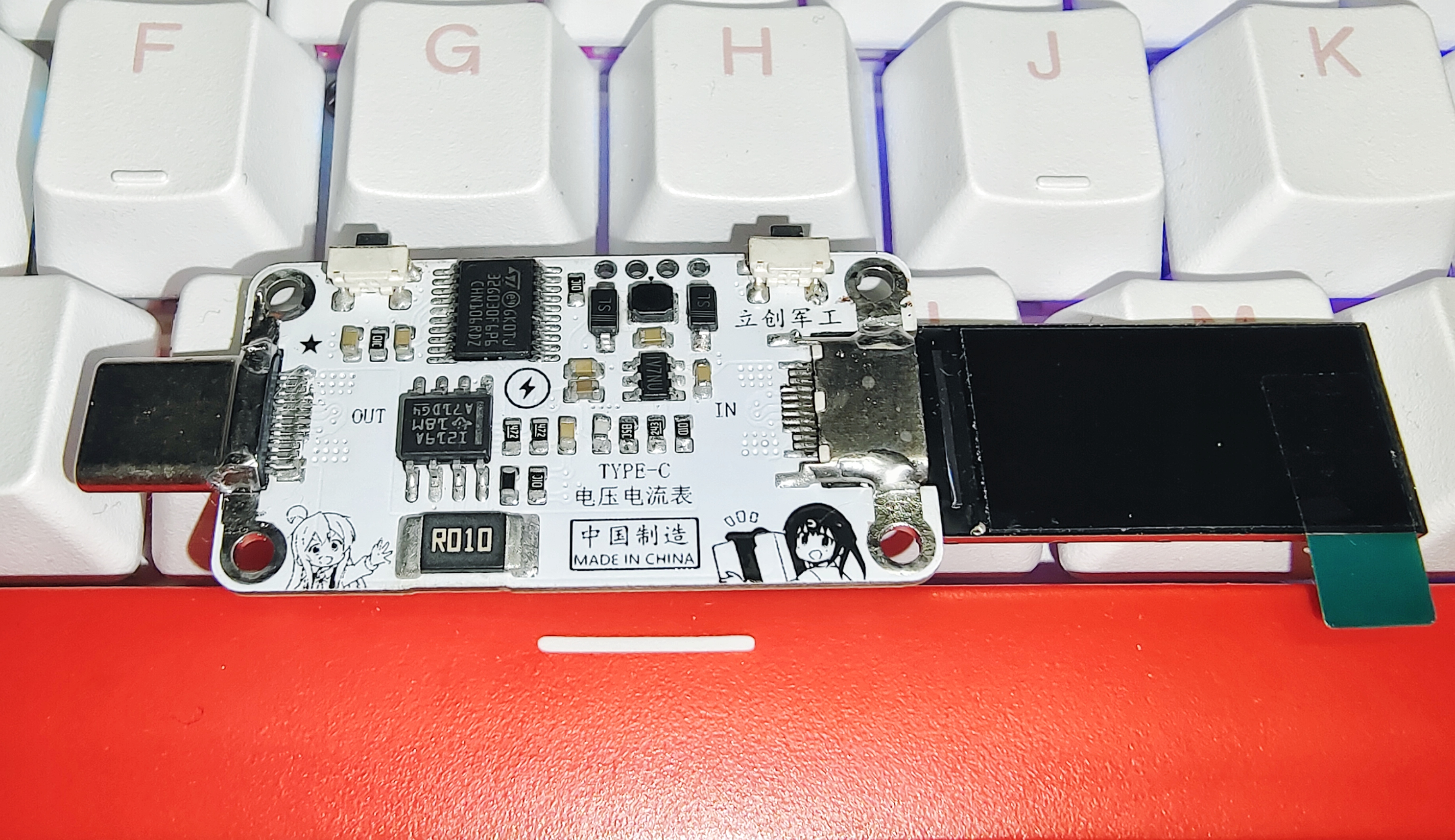
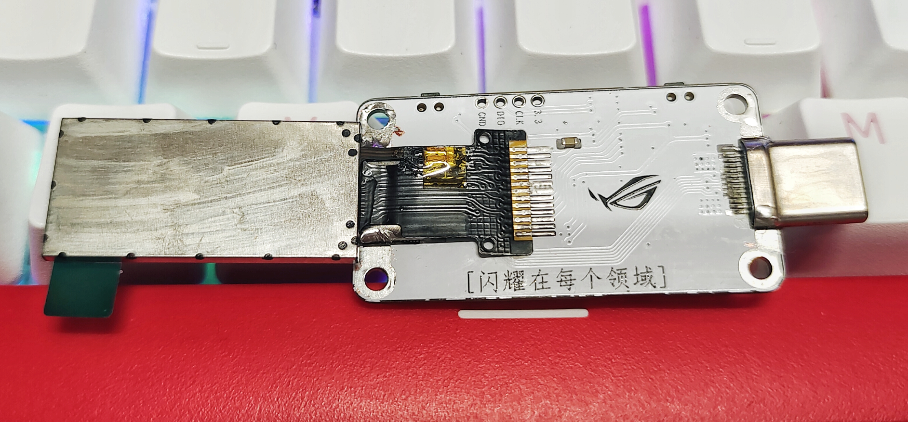
Interface: TYPE-C 24P Female →→→ TYPE-C 24P Male
Range: Maximum Voltage 28V, Maximum Current 8A, Peak Power 224W Main
Control Chip: STM32G030F6P6 (LCSC Mall ID: C724040)
Screen Information: 0.96-inch TFT Color 13Pin
Button Functions: KEY1 Screen Orientation Flip, KEY2 Interface Switching
Usage: Connect the voltage and current meter in series between the data cable and the device being monitored. It will automatically power on after power-on, automatically start detecting and displaying data on the screen. ~
Performance buffs added for Zhenxun and Meiboli
Update Log:
Project verification successful.
Open source project released on 2023/6/2 April 16, 2024:
To avoid being misled, the power chip reference number on the PCB and schematic was changed from MP2452 to MP2451. It was originally MP2451, but because I had previously placed two chips, the EDA system automatically overwrote the reference number, resulting in MP2452. April 20, 2024:
Notes:
Source code: [Click here to go to the source code address]
Programming software: PowerWriter or any tool that can program this microcontroller...
The programming file is attached: ROG-000V000A000W.HEX.
Many blue texts on the open-source page contain URLs; you can click to jump to them.
This project has passed a long-term random stability test of up to 10 months, so it's being open-sourced today.
When soldering the screen, be careful not to break the ribbon cable. When bending the screen ribbon cable, be careful not to use too much force.
When cleaning the PCB, be careful not to get the cleaning solution into the interfaces. It's best not to let the inductors get wet with the cleaning solution, especially the screen! Even a little bit of cleaning solution will kill it!
Since I didn't have any higher-power devices using Type-C as the power supply interface, nor a DC-to-Type-C cable, I didn't test higher power outputs, only the highest I tested was over 100 watts.
Because I didn't adjust or modify the BOM (Bill of Materials), some components in the BOM directly generated by JLCPCB EDA might not match. It's best to carefully compare the component names and values on the schematic and PCB before purchasing.
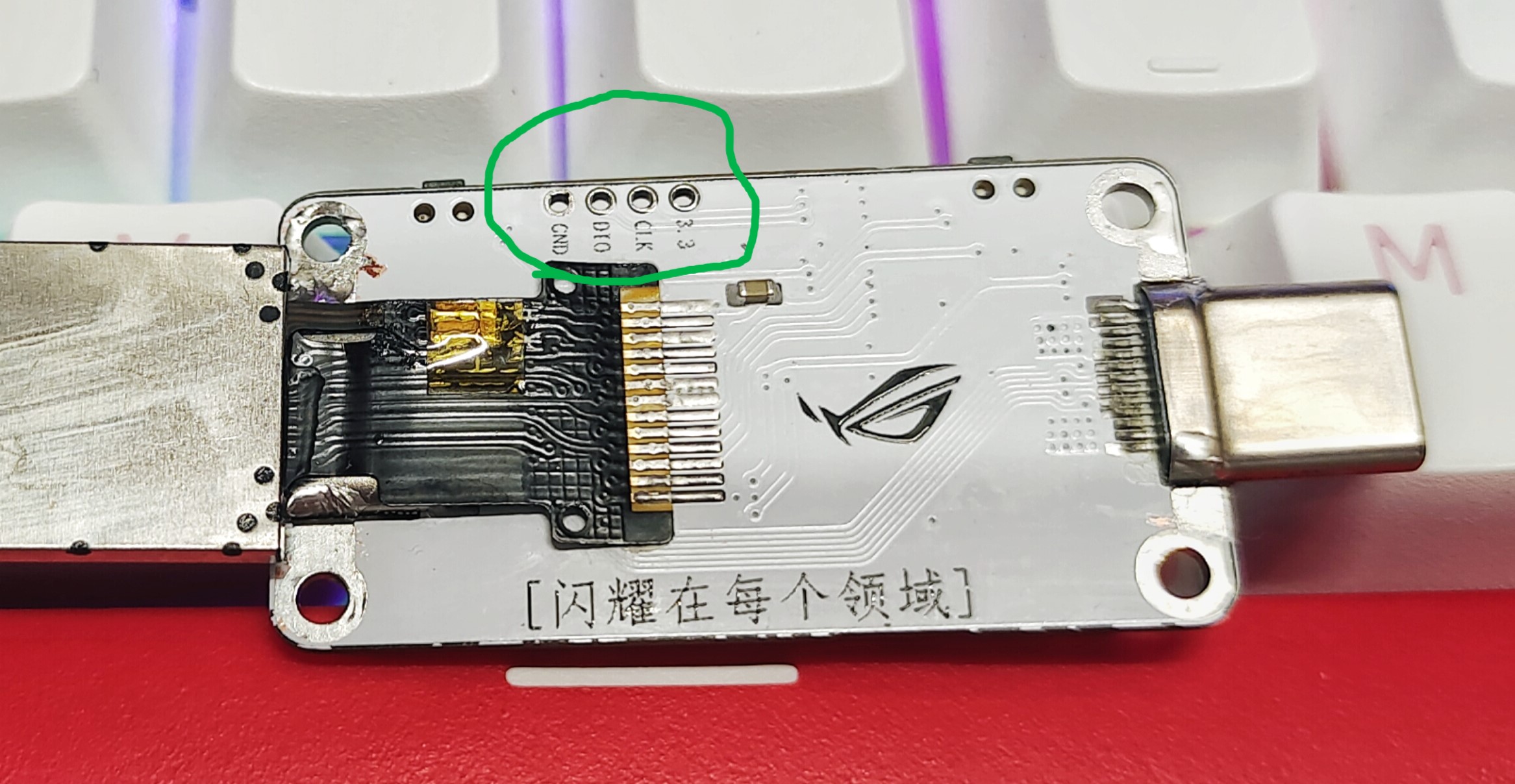
The green-boxed vias in the image are programming holes (for programming the device).
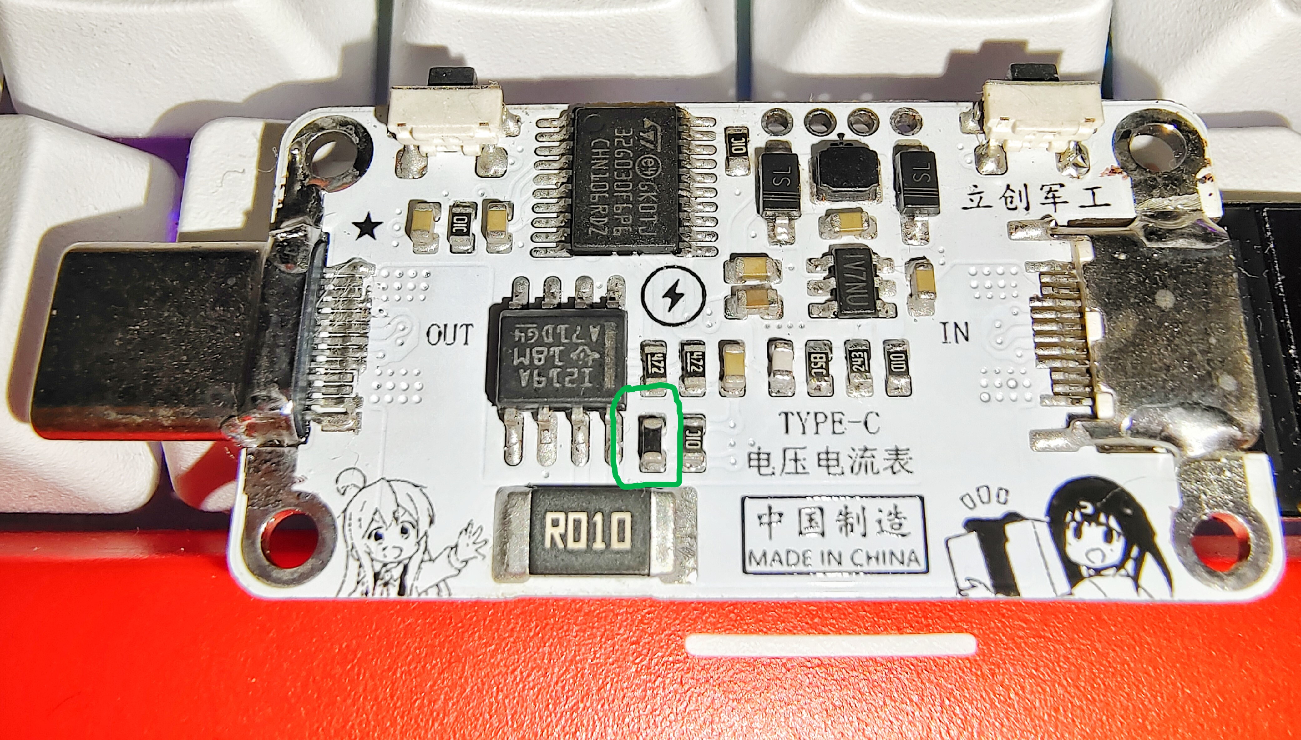
The green-boxed components are NTC resistors (used to detect the temperature of the sampling resistor).
Download the programming software PowerWriter from icworkshop.com.

Testing:
The different interfaces displayed on the screen in the following images are because the voltage and current meter code includes three interfaces. You can switch between them using buttons.
It can be used with a mini docking station to measure the voltage/current/power of extended devices.
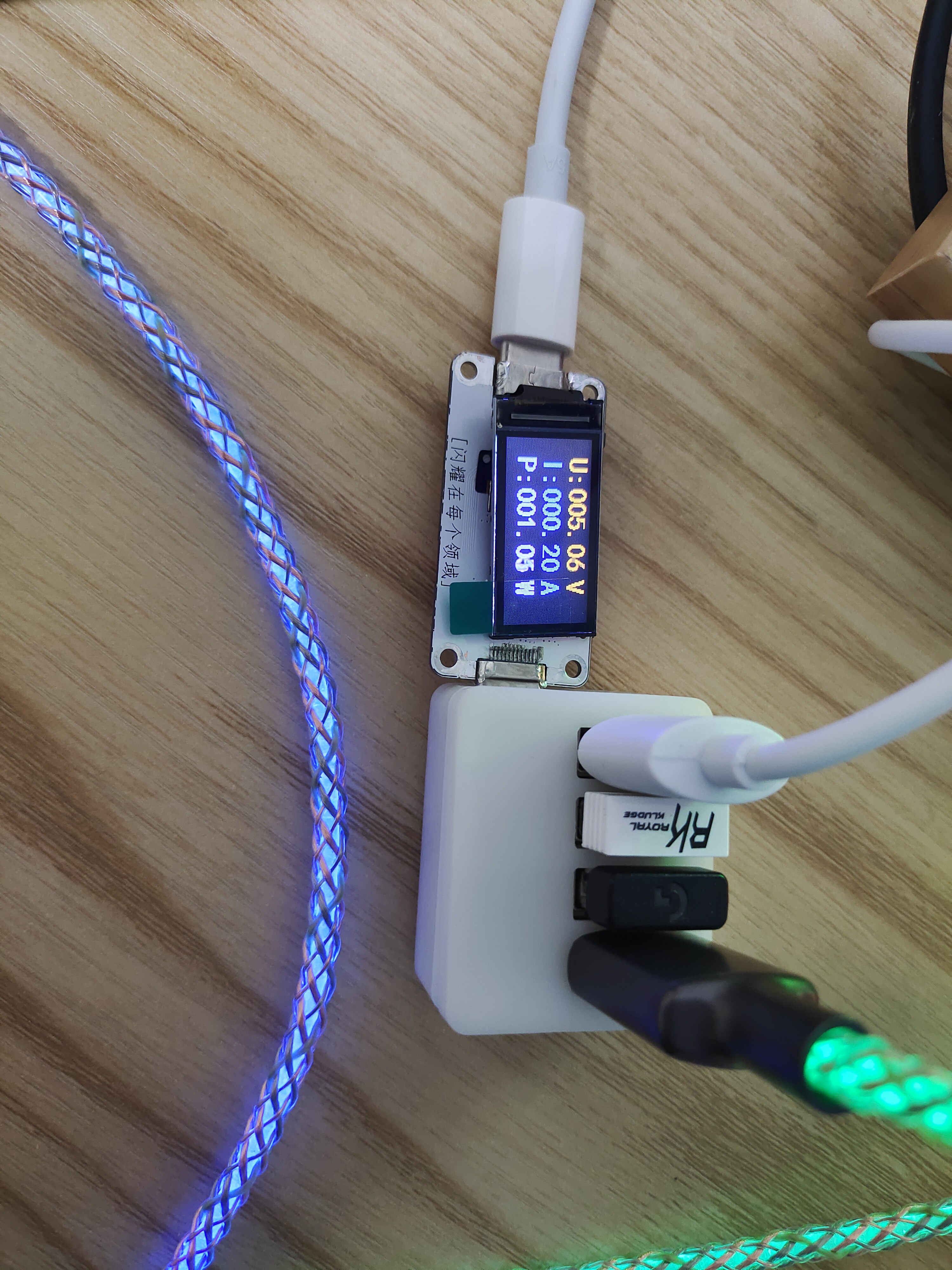
It can also be used with a 5V centralized power supply system to monitor the voltage/current/power of electrical equipment and perform

high-power stability testing!
The TYPE-C port shown in this diagram is a pass-through and does not affect communication of any protocols. As shown in the diagram, it has been working for over 10 minutes; the laptop adapter's PD65W has been triggered and is supplying power to the laptop. Voltage, current, and power values were then monitored by the meter...
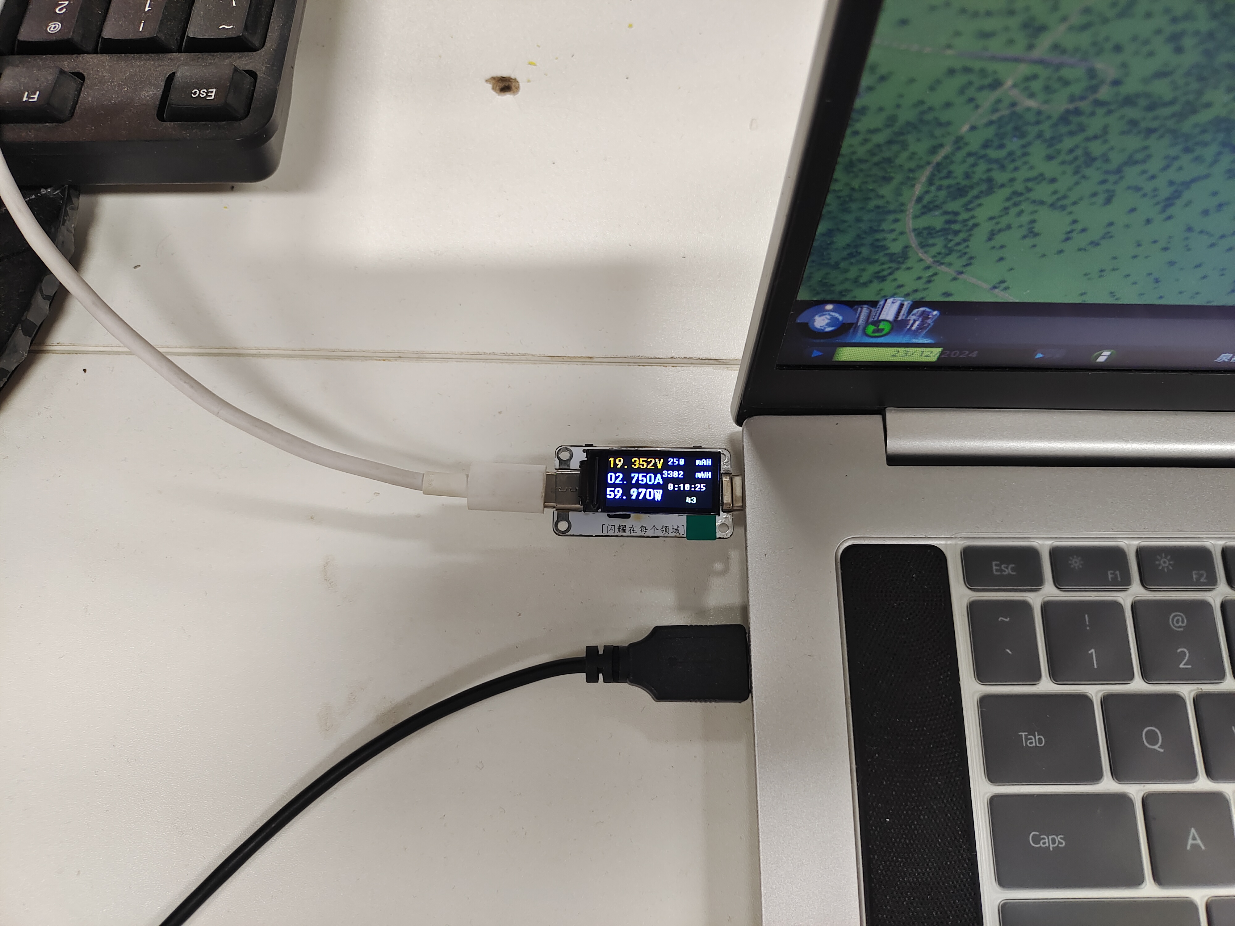
High-power stability test!
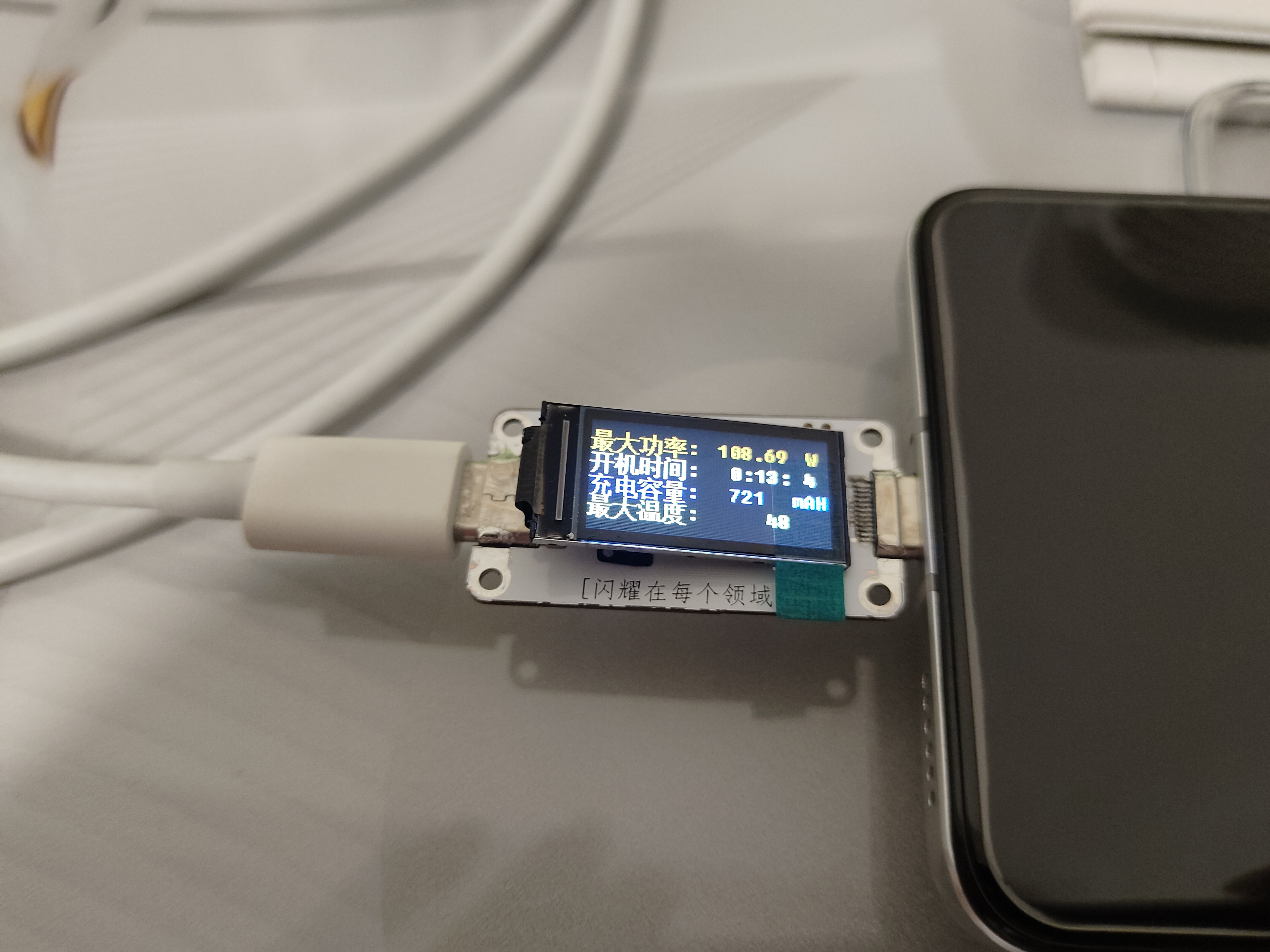
Charging a mobile phone with the original 120W fast charger, as shown in the diagram, after 13 minutes of charging (NTC resistor at the sampling resistor), the maximum temperature at the sampling resistor was 48℃, approximately 720mAh was charged, and the maximum power was 108.69W.


 京公网安备 11010802033920号

 MM1Z16


