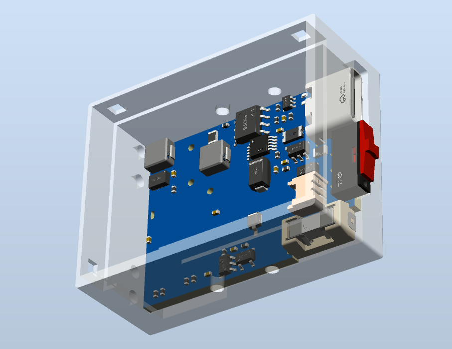
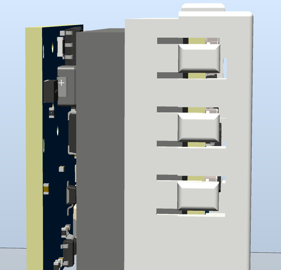
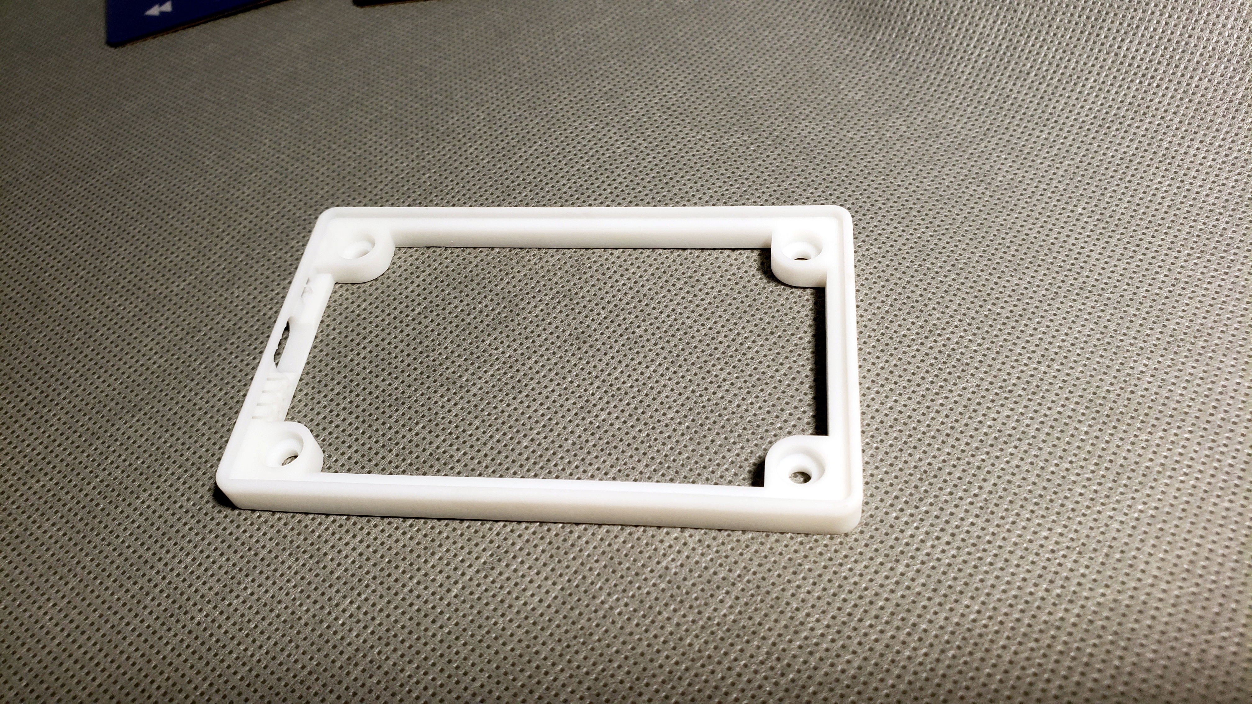
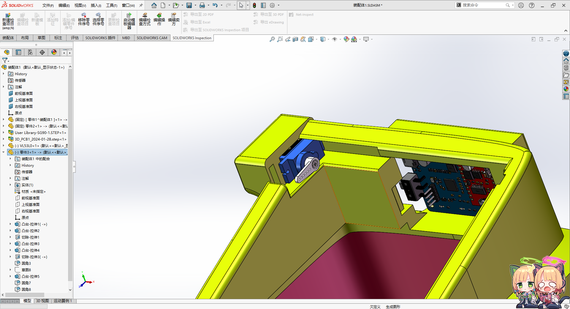
and its casing is designed using SolidWorks.
The STC32F12K54, used as the main controller, is a low-power desktop clock with an average power consumption of 1.6mA (6.2mW) in TV mode and can operate for approximately 24 days. It also features integrated RTC, temperature and humidity, magnetic field, acceleration, barometric pressure, and light intensity sensors for development purposes.
【Low Power Consumption】Desktop Clock 4.0
▎Update Log⚫2024.01.25
Released open-source PCB for the project 【Control Board 4.0.2】【Power Board 2.8.4】
⚫2024.03.02 Updated PCB 【Control Board 4.0.3】【Power Board 2.8.5】
Released public firmware YQ-240229A
open-source shell STL, STP files
⚫2024.03.06 Updated PCB 【Control Board 4.0.4】:
①Modified RTC battery circuit to adapt to replacement component RX8900CE
②Corrected SHT40 to SHT41
BOM upload
⚫2024.03.14 Upload open source project + source code (without alarm clock).
Upload 2.8.5 power board operation manual SOP.
Corrected the package of 50mR resistor in BOM and changed the 50mR and 200mR resistors.

After countless bugs and debugging, board making and soldering, I finally made my low power desktop clock barely open source.
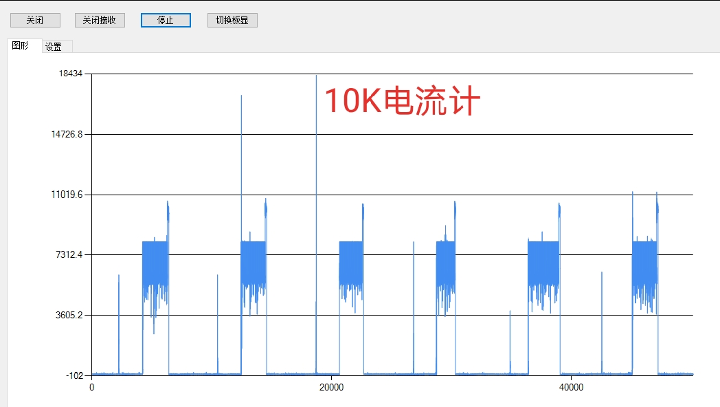
First, regarding the power consumption issue that everyone is concerned about, we have only compared two solutions so far (OLED 5V 255W brightness test). The power consumption increased due to the addition of code and the display of alarm clock and silent UI, so we had to reduce the brightness.
[Note: Due to the addition of alarm clock display, full year display, full day of the week UI display, and other function algorithms, the power consumption increased from 1.69mA to 1.85mA. Code optimization will follow.]
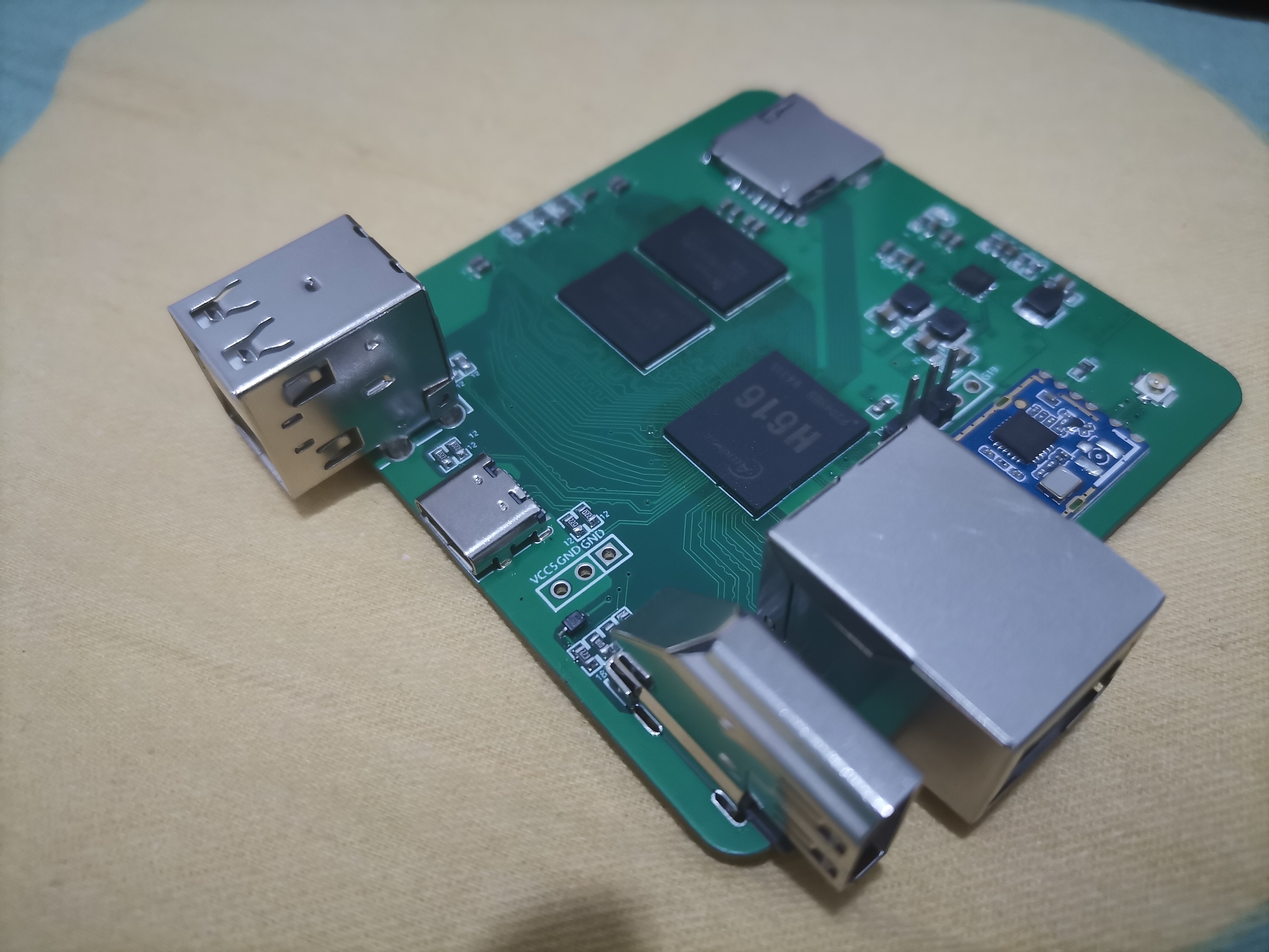
Main controller
test firmware version
stable main frequency
solution (including power board): Overall standby current
3.84V, operating power consumption (TV mode 30 minutes average),
theoretical sleep duration (1000mAH),
theoretical operating duration (1000mAH):
STC32G12K128
/
30M
7.8uA
2.1mA (8.2mW)
14.1 years
18.8 days;
STC32F12K54
YQ-240229A
52M
30uA
1.85mA (7.067mW).
3.66 years
21.81 days
STC8H8K64U
/
/
/
/
/
/
Future versions will include an automatic brightness adjustment mechanism, automatically lowering the brightness at night or entering sleep mode. Theoretically, it can last for more than a month.
However, the actual usage time is highly dependent on the brightness. During normal display (excluding scrolling menus), power consumption is primarily on the screen, with very little power consumed by the MCU. We have already tested the 8080 communication solution, and the SPI solution is more power-efficient.
Therefore, the actual usage time depends on the brightness settings and the displayed content. Contextual test data and displayed images are based on factory default settings (OLED 5V 255W brightness, 3.84V battery power).
At first, I was so captivated by the STC32G's 7.8uA that I reluctantly gave up on the STC32F. Then I realized my battery is huge—1000mAh! After calculating the standby current, I discovered that even with a 30uA standby current, it could last for three and a half years.
Table
of Contents: 1. Control Board Parameter Introduction;
2. Power Board Parameter Introduction;
2.1 DC-DC Lithium Battery Charging;
2.2 Lithium Battery Protection;
2.3 DC-DC Buck (MCU + Sensor Power Supply);
2.4 DC-DC Boost (OLED Power Supply)
2.5 Charging Current Detection
2.6 FFC Interface Definition
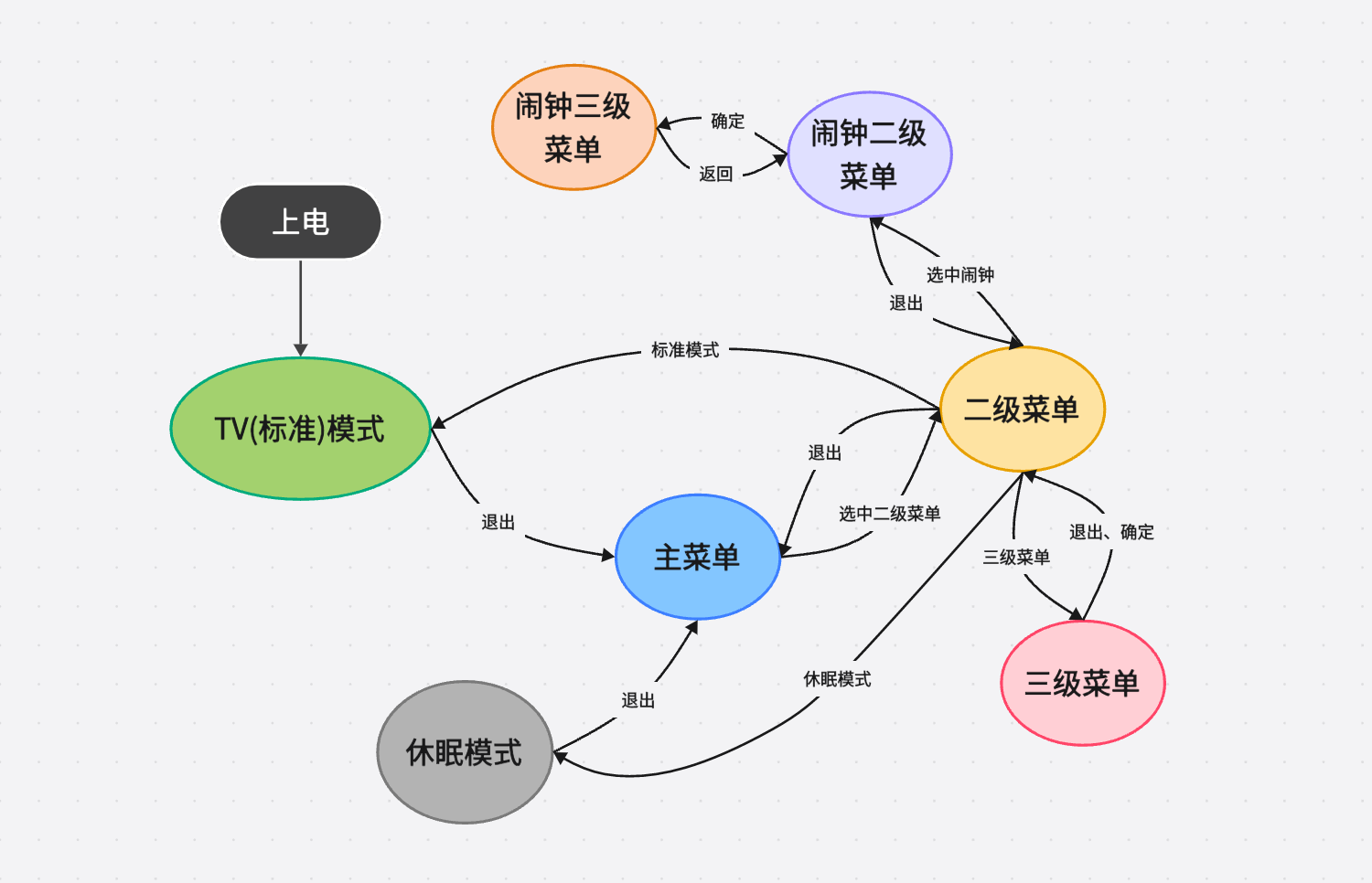
3 Function Demonstration 3.1 UI
Operation Diagram
3.2 TV Mode
3.3 Main Menu 3.4
Secondary Menu
3.5 Tertiary Menu
3.6 Compass 4
Program Architecture
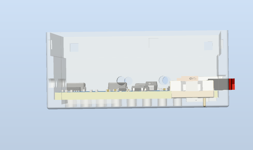
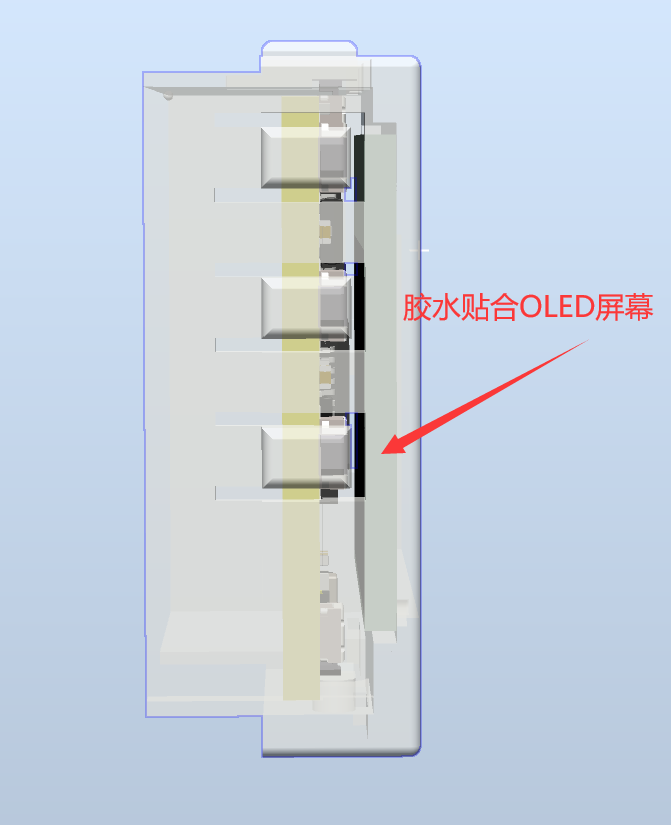
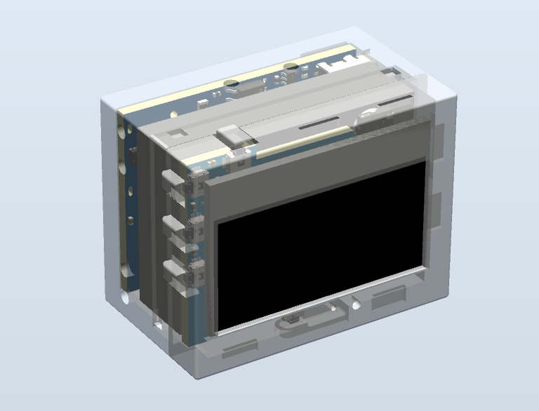
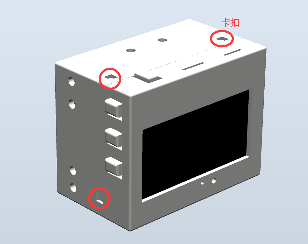
5 Structure Demonstration
=== ... ●RTC: INS5699 ●Light Intensity Meter: BH1745 ●Magnetometer + Accelerometer: BMC050 ● Passive Buzzer (but has an independent 4K square wave generation circuit, does not occupy MCU resources) ● Vibration Switch ● Buttons X5: +, -, OK, Exit, Reset === ...
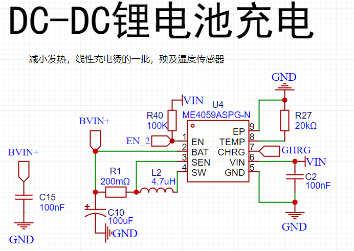
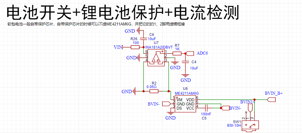
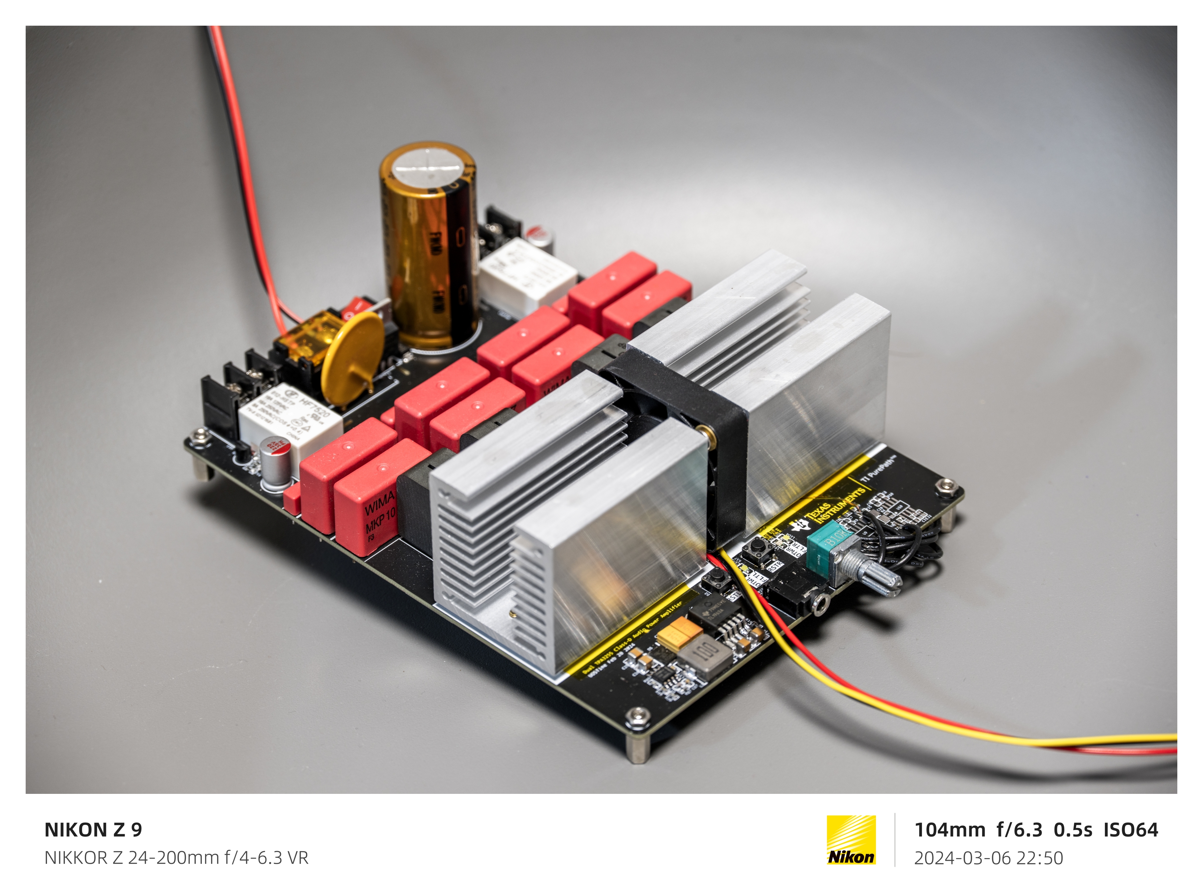
●2.2 Lithium Battery Protection
ME4211AM6G (Generally, lithium batteries have built-in protection and do not need to be soldered)
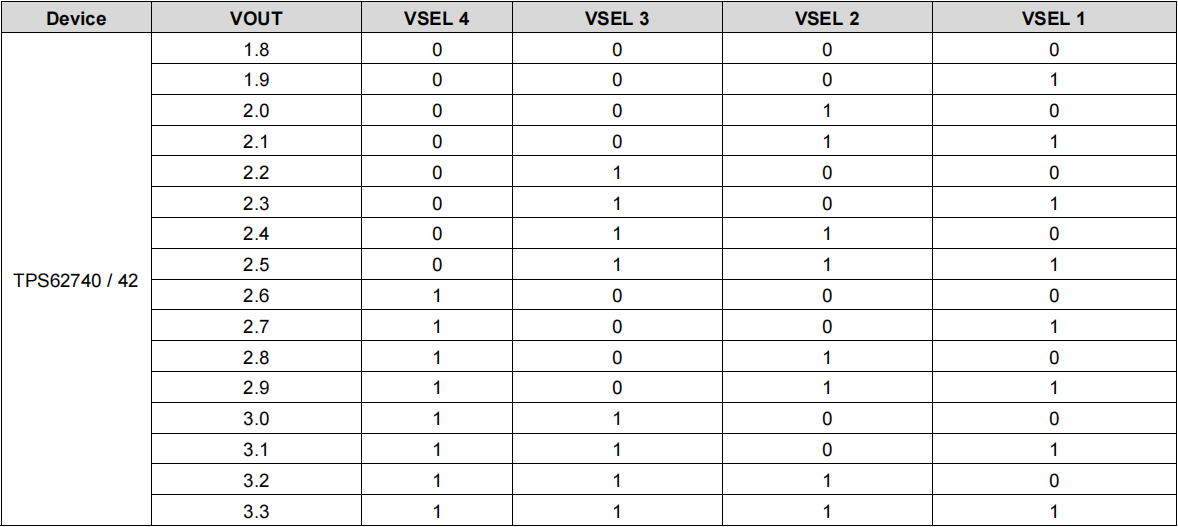
●2.3 DC-DC Step-Down (Motherboard Power Supply)
TPS62740DSSR (10uA has 90% efficiency, standby current Iq=360nA)

TPS62740DSSR Test
Output Voltage (V
) Output
Current (mA ) Power (mW) Input Voltage (V) Output Current (mA) Power (mW) Efficiency 2.816 0.858536585 2.417639024 3.81 0.664 2.52984 95.56% 2.816 28.16 79.29856 3.81 22.75 86.6775 91.48% 2.809 280.9 789.0481 3.686 244.5 901.227 87.55% The voltage can be selected by configuring the pins to your liking: ● 2.4DC-DC boost (OLED power supply) MT9700+MT3608L (The boost converter does not have current limiting protection, so add a separate current limiting protection chip MT9700; you can remove it if you are confident). The feedback resistor can be controlled through two I/O ports on the motherboard to obtain 5V, 6V, 7V, and 8V (actually, it would be more reasonable to have four levels covering the brightest and darkest current ranges of the OLED; this will be improved later). Below are the efficiency figures for some boost chips I tested: TLV61048 (300mV ripple) 10uf Output Voltage (V) Output Current (mA) Output Power (mW) Input Voltage (V ) Input Current (mA) Input Power (mW) Efficiency 5 1.515 7.576 3.880 2.360 9.157 82.73% 5 3.030 15.150 3.841 4.600 17.669 85.75% 5.037 156.250 787.031 3.740 247.000 923.780 85.20% MT3608 (200mV ripple) 22uf Output Voltage (V) Output Current (mA) Output Power (mW) Input Voltage (V) Input Current (mA) Input Power (mW) Efficiency 5 1.042 5.208 3.863 1.610 6.219 83.74% 5 16.667 83.333 3.856 24.130 93.045 89.56% MT3608L (72mV ripple) 10uf Output Voltage (V) Output Current (mA) Output Power (mW) Input Voltage (V) Input Current (mA) Input Power (mW) Efficiency 5.018 1.521 7.630 3.873 2.230 8.637 88.35% 4.986 3.030 15.108 3.873 4.360 16.886 89.47% 5.037 156.250 787.031 3.740 247.000 923.780 85.20% TPS61041 (250mV ripple) 22uf Output Voltage (V) Output Current (mA) Output Power (mW) Input Voltage (V) Input Current (mA) Input Power (mW) Efficiency 5.021 1.046041667 5.252175208 3.853 1.593 6.137829 85.57% 5.021 16.73666667 84.03480333 3.853 24.647 94.964891 88.49% 5


1.5151
7.5755
3.841
2.16
8.29656
91.31%
5
3.03
15.15
3.841
4.31
16.55471
91.51%
MIC2251
Output Voltage (V) Output Current (
mA)
Output Power (mW)
Input Voltage (V)
Input Current (mA)
Input Power (mW)
Efficiency
5
16.65
83.25
3.861
24.762
95.606082
87.08%
shows that the TPS61041 and MT3608 have high efficiency, but these two chips exhibit significant voltage fluctuations, almost reaching 1V, under light-load PFM mode. Therefore, the MT3608L chip was chosen as a compromise.
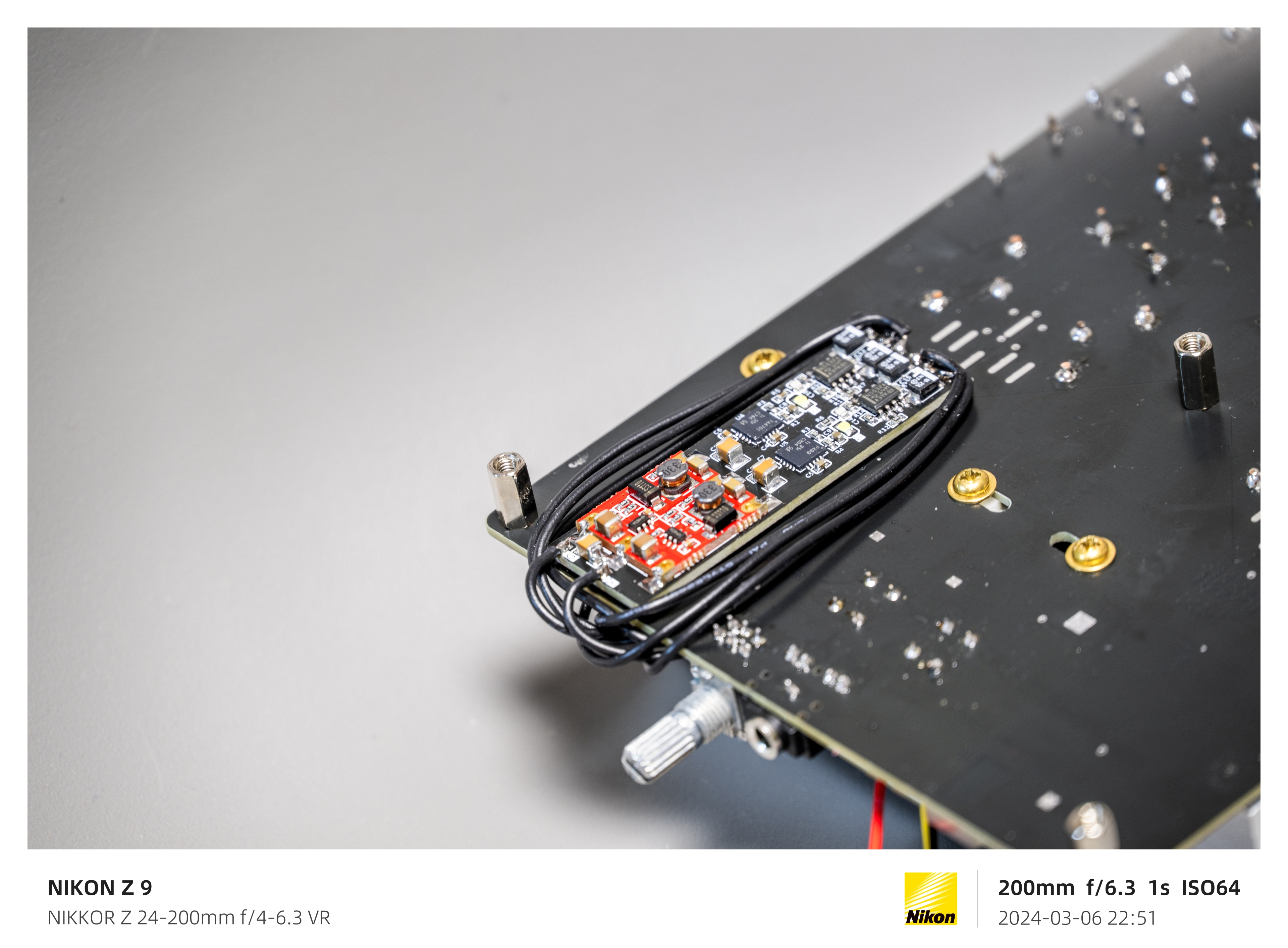
●2.5 Charging Current Detection:
INA181A2IDBVT + 50mΩ Resistor
●2.6 FFC Interface Definition

=================================================================================================
3. Function Demonstration
● 3.1 UI Operation Diagram
● 3.2 TV Mode
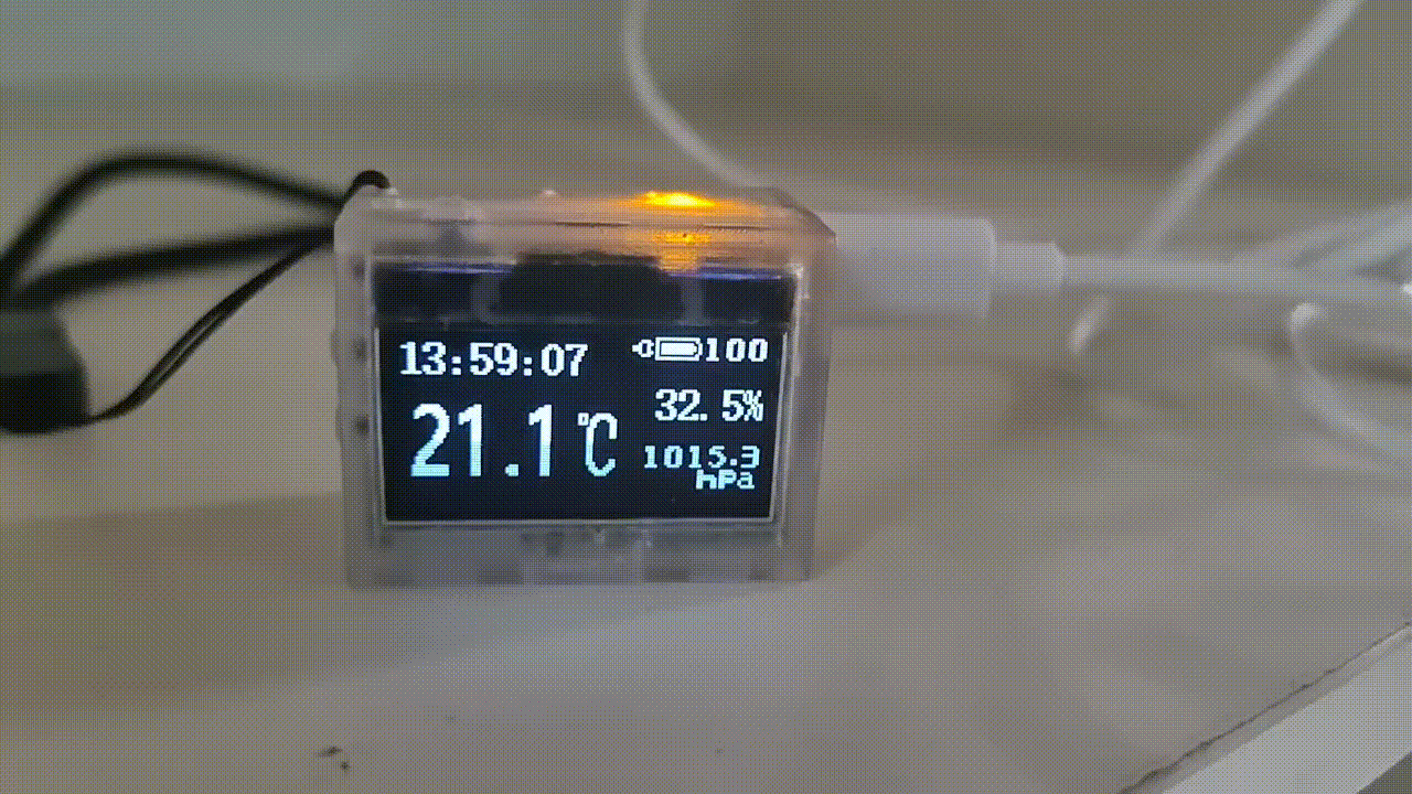
Upon power-up, the system defaults to TV mode. This mode displays the time for 40 seconds, temperature, humidity, and air pressure for 10 seconds, and battery status for 10 seconds (duration can be adjusted to preference). The average power consumption is 1.6mA.
① Time Display Interface: The time display interface shows the current hour, minute, and second in a 32x16 format (scrolling!), and the current year, month, day, and weekday in a 16x8 format. It also displays the battery level. When charging is connected, a charging connector icon will appear on the side of the battery. The total power consumption of this interface is approximately 1.7~1.9mA

(refresh the webpage if the GIF is choppy).
② Environment Display Interface: The environment display interface shows the current temperature in a 32x16 format, the current hour, minute, second, and humidity in a 16x8 format, and the current air pressure in an 8x8 format. It also displays the battery level. When charging is connected, a charging connector icon will appear on the side of the battery (light leakage is not this obvious to the naked eye).

(Refresh the webpage if the GIF is choppy).
③ Battery Display Interface: The battery display interface will show the current hour, minute, and second in a 16x8 size, along with a large battery icon, the current voltage, and the charging current. A rather unsightly charging animation will be displayed during charging (the voltage is 4.3V because I replaced the chip and it hasn't been calibrated yet).
(Refresh the page if the GIF is choppy).
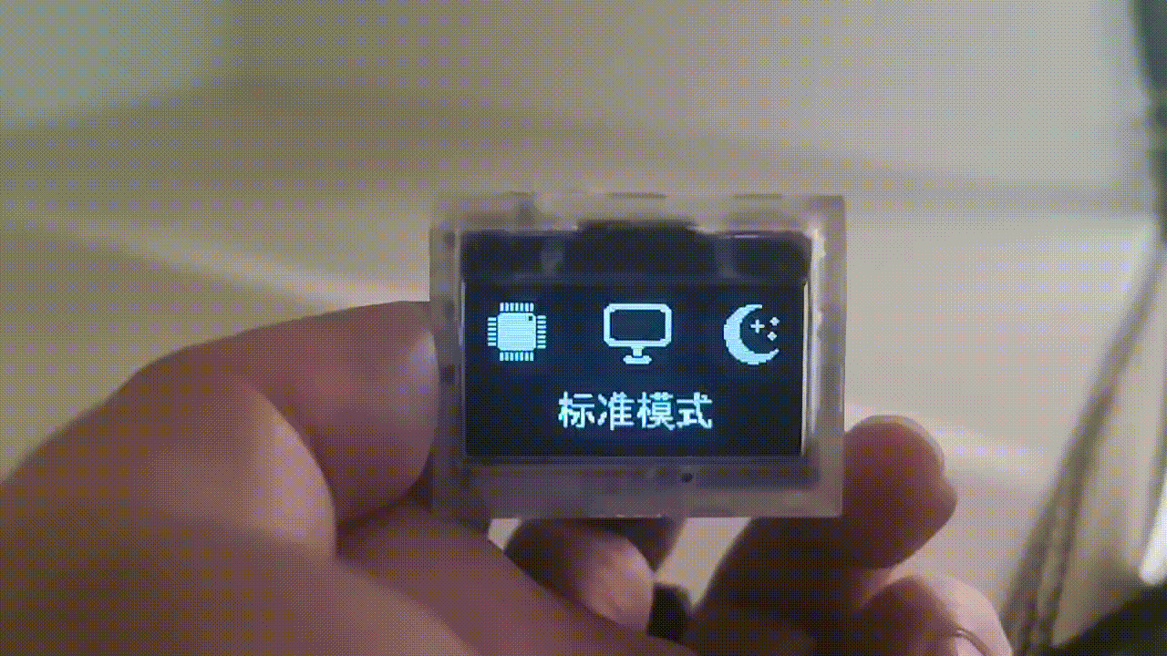
●3.3 The main menu
has 16 preset sub-menus. The total power consumption when scrolling is approximately 2mA (the following is progress, (×) indicates not yet developed or supported):
● Standard Mode (√)
● Sleep Mode (√)
● Environmental Information (√)
● Brightness Setting (usable)
● Compass (√)
● Level (×)
● Time Setting (√)
● Alarm Clock (√)
● Incremental Alarm Clock (×)
● Stopwatch (×)
● Sound Setting (√)
● Flashlight (√)
● Power Management (√)
● System Settings (×)
● System Information (√)
● Factory Mode (×)
(Refresh the page if the GIF is choppy).
●3.4 Sub-menus
can be set by pressing OK. The total power consumption when scrolling parameters is approximately 4mA.

(Refresh the page if the GIF is choppy)
●3.5 Three-level menu:
Press OK under the second-level menu to make settings. The total power consumption is approximately 1.4mA.

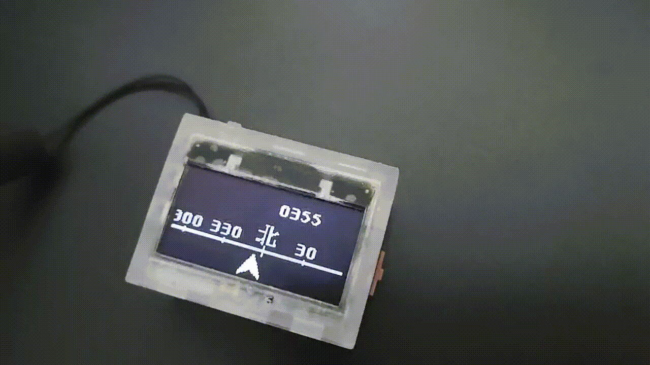
●3.6 The compass
does not have a fixed calibration. Details such as the position of the angle display are not adjustable. When using it, you need to slowly rotate it around in place to calibrate it. The current power consumption in this mode is 1.3mA
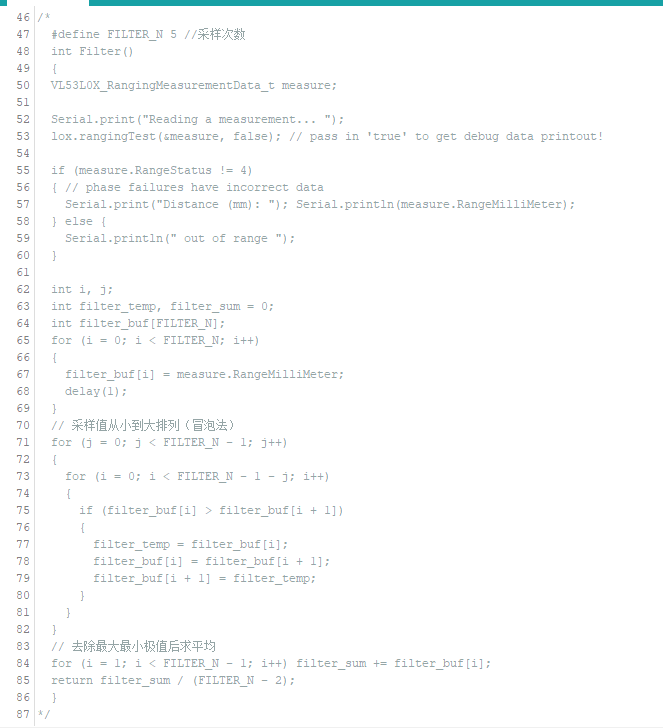
. === ... When developing the first and second generation clocks, we discovered a significant issue: the MCU frequently experienced delays during task execution. For instance, when scrolling numbers, a 32-pixel translation required 32 separate translations, with a 6-millisecond interval between each translation. This resulted in a 186ms idle time (31 x 6 = 186ms), a critical problem. If the clock refreshed every second, 18.6% of the time was wasted waiting. Similarly, after sending a measurement command to a sensor, a waiting period was required to read the measured value. To address this MCU idleness, a power-down mode could be implemented to reduce power consumption. However, this introduces a new problem: how does the MCU know when to wake up? A power-down wake-up timer can be used, allowing the MCU to wake up at a specified time after a sleep period. But this raises another question: how does the MCU know when to wake up next? For example, if a 32-pixel translation requires 32 steps, how does the MCU know it needs to perform another 32 steps with 6ms intervals after the first one?
To solve this problem, I devised a method: introducing two arrays, one for "sleep time" and the other for "task number" (each bit represents a task). The values in the two arrays correspond one-to-one. For example, to perform a 32-pixel translation, which requires 32 operations, I first reserve 32 tasks in the "sleep time" and "task number" arrays, as shown in the figure below. Each time,

the MCU checks the values in the "sleep time" array [0] and the "task number" array [0]. If they are not equal to 0, the value of the "sleep time" array [0] is loaded into the power-down wake-up register, and the MCU goes into sleep mode. After waking up, the MCU matches the corresponding task according to the value of the "task number" array [0]. After the task is completed, the value of the entire array shifts one position to the left. When the value in the "sleep time" array [0] and the "task number" array [0] is 0, it means that the UI refresh task has been completed, the power-down wake-up register is closed, and the MCU completely enters sleep mode, waiting for the external button to interrupt the task and wake it up.
However, the project doesn't only have one task: OLED screen refresh. For tasks requiring sensor measurements, to ensure timeliness, it's impossible to schedule measurements after the UI refresh is complete. We want to achieve both simultaneously. This requires writing an insertion algorithm to insert tasks into the task queue. For example, inserting a barometric pressure measurement task ("task number array" bit1 = 1) into the queue requires a 15ms wait (6+6+3) before insertion into the queue shown in the diagram above, as shown below. It can be seen that when values cannot overlap, the queue insertion needs to be interrupted.

Another example: inserting a barometric pressure measurement task into the queue requires a 12ms wait before insertion into the queue shown in the diagram below. It can be seen that when values overlap, the queue insertion does not need to be interrupted. Only the bit corresponding to the task number needs to be added.

So far, the low-power task scheduling algorithm is complete, but one problem remains: during sleep mode, if an external interrupt is input, the MCU will prematurely end sleep, potentially causing abnormal sensor sampling and affecting the user experience. At this point, the sleep algorithm needs to be optimized. Upon waking, if the timer in the wake-up register hasn't expired, the value should be filled back and the system should return to sleep until the timer value is 0. But
the process isn't over yet. To further reduce power consumption, we need to do more. The most power-consuming task for the MCU is actually during screen refresh. This requires MCU involvement when sending data via SPI, preventing other tasks. We can use DMA with a double buffer. First, buffer 1 is filled, and then the DMA sends data from buffer 1. While buffer 1 is being sent, buffer 2 is filled, and so on, alternating and repeating to improve the MCU's efficiency.
However, simply sending data via DMA still consumes more power because it requires moving the data from flash to XRAM and then sending it out via DMA, which takes time and is less efficient than sending the data directly from flash.
In this case, we can take advantage of the fact that when the MCU enters idle mode, the MCU stops working, but the peripherals can still operate. If area 2 is filled but area 1 is not yet finished sending, the MCU can be put into idle mode. In this mode, the MCU stops working, but the peripherals can still operate. It waits for the SPI DMA to complete before waking up to execute other programs.
This further reduces power consumption.
In addition, there are various optimizations to local refreshes, meticulously reducing power consumption .
===
...


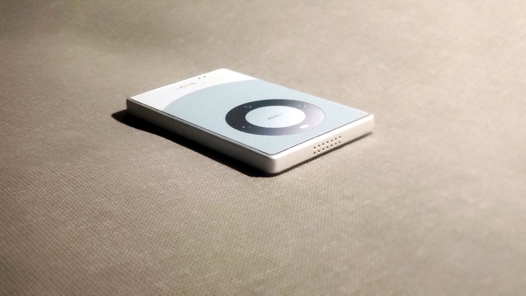
The Mate 60 mini
version project aims for simplification, based on the Mate 60, but scaled down to a card-sized form factor
. Screens are too big now, too small for small hands, and you're afraid of dropping it and breaking it.
It supports Type-C charging
, touch recognition on the back with three independent sections
, no buttons on the sides for a minimalist look,
speaker holes
at the bottom and top, and physical in-screen buttons for a real tactile experience, not a motor-simulated design. It also features
four built-in magnets for easy attachment.
(Video demonstration:
https://www.bilibili.com/video/BV1yt421t7Mh/

) Circuit description
: Adjusting the size of C26 adjusts touch sensitivity.

Two types of storage chips are available, choose one, and capacity can be selected as needed.

The core uses CH7002.

Charging...


The above content is purely fictional and should not be taken seriously. If you do, you are solely responsible for the consequences. Electronics are boring
, life needs entertainment! Why not share the fun with others? The above content is purely fictional and should not be taken seriously. If you do, you are solely responsible for the consequences. Electronics are boring, life needs entertainment! Instead of fooling yourself for fun, why not share the fun with others!
The above content is purely fictional and should not be taken seriously; if you do, you are solely responsible for the consequences. Electronic games can be boring, but life needs entertainment! Why be silly and have fun with others instead of just fooling yourself!
Overview:
No programming required. A clever
use for holidays.
A special
card-sized version
for collecting.
Supports hanging ropes.
Large capacity storage.
Power switch.
Freely stick to refrigerators.
Music storage is flexible.
Details:
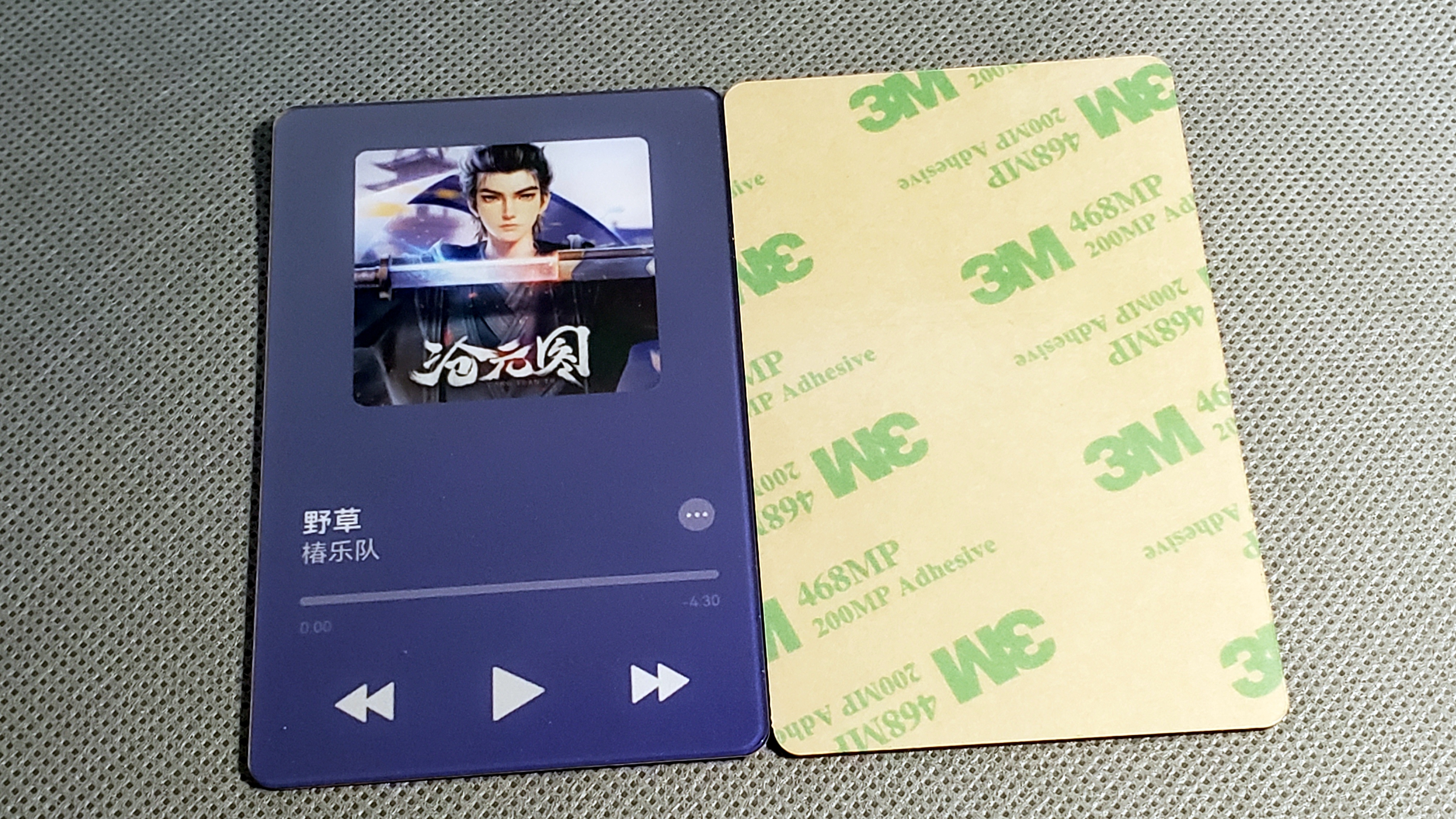
This project mainly uses JLCPCB's color PCB, 3D printing + painting, and JLCPCB's panel printing service.
Components mainly use large solder pads for easy soldering and replication.
The battery is a 302530 lithium battery
. Speaker thickness should not exceed 4.3mm. 0.5W 8-ohm
magnets: four, round, 6mm diameter, 2mm thickness.
PCB thickness: 1.6mm .
Panel thickness: 1.0mm. Adhesive backing.


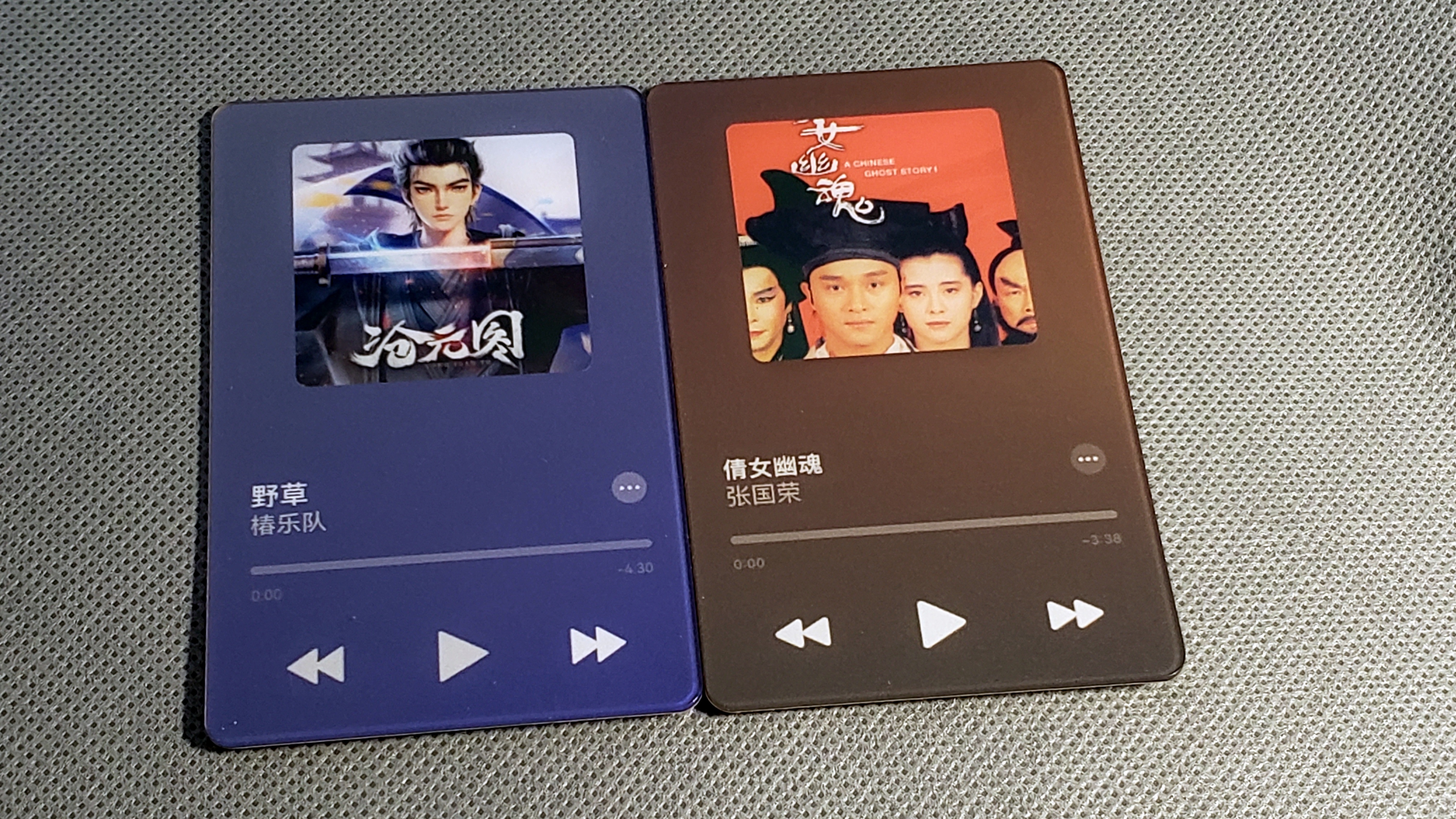

A touch switch on the front for easy pressing, and three touch buttons on the back for audio switching.
After plugging into a computer, a USB flash drive appears with internal files; simply replace them. No programming knowledge required.
Quickly transfer your favorite music or other files, use it as a music card, or a prank tool!

Electronic Fooling Game Call for Submissions!
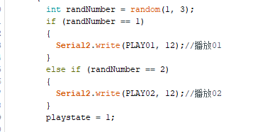
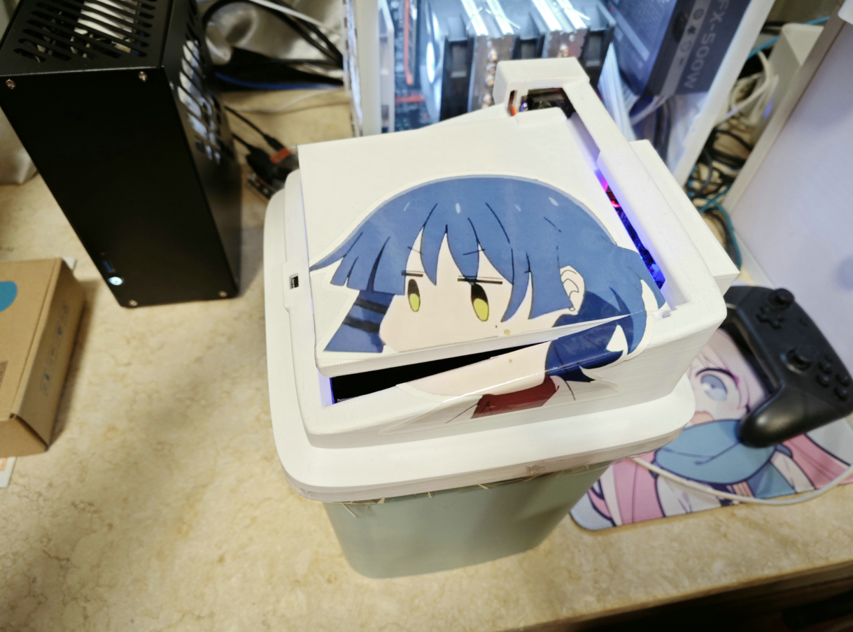 uses a Raspberry Pi PCIO2040 as the main controller, a servo motor to control the trash can lid, a VL53L0X as the distance sensor, and a DY-SV17F for voice announcements. It's a fully automatic trash can dispenser (basically a smart trash can lid).
 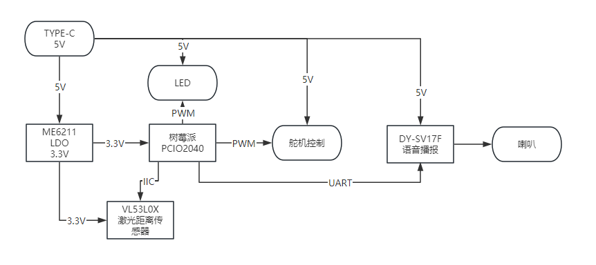 3. Circuit: The main
 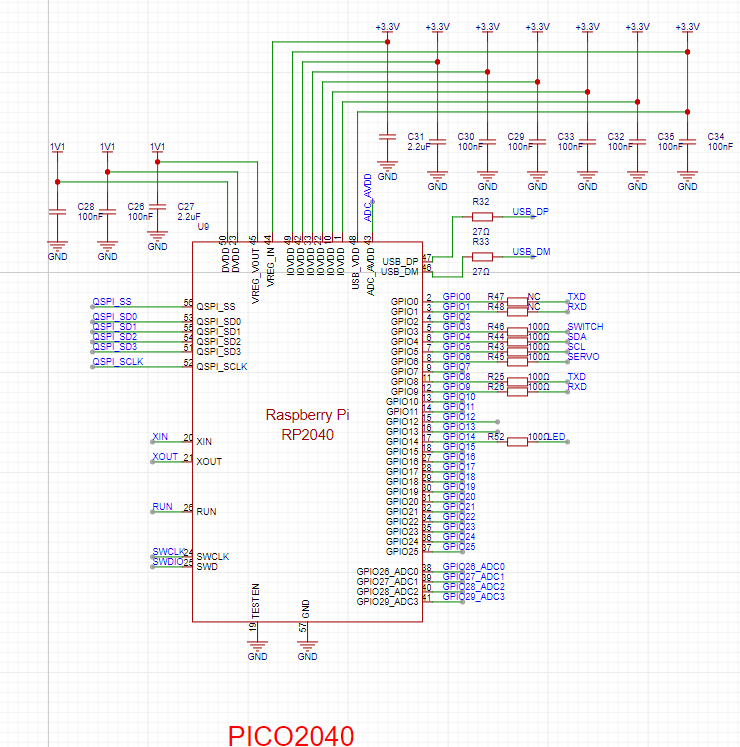 The TXRX resistors are not connected
  to IICs; pull-up resistors are used.
 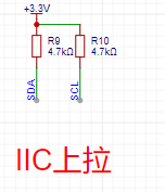 Other components are standard circuits and will not be discussed further.
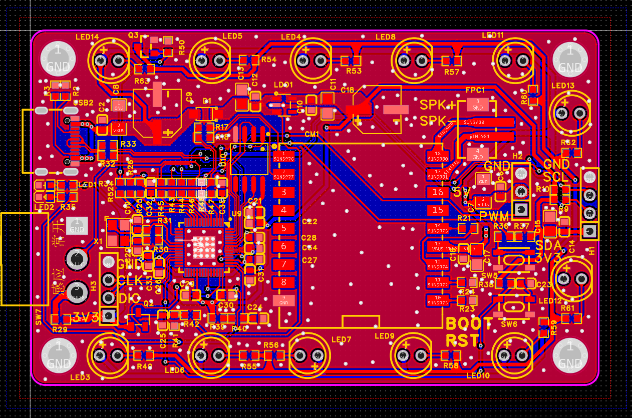
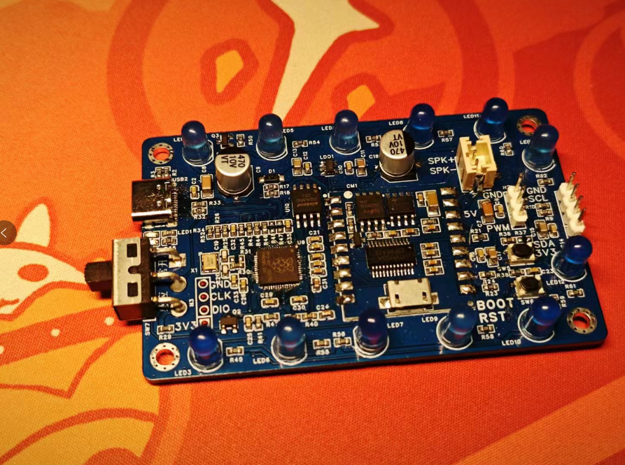 4. Modeling: The PCB is


 entertainment features
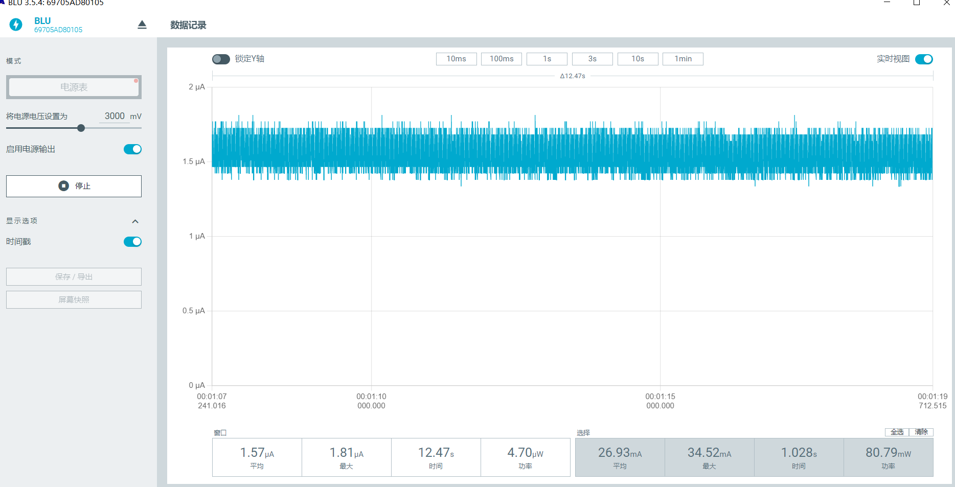


 The software
 and its casing is designed using SolidWorks.


 京公网安备 11010802033920号

 HCTS244DTR


