The flight controller outputs 12V GND TX RX to this board, which then connects to the various connectors on the module, simplifying the wiring process. The accompanying diagram uses the first version with a direct-plug socket; please refer to the schematics and PCB layout in the actual project.
A screenshot showing the effect when using the 8812EU network card is shown below.
This 2-cell supercapacitor spot welder has a built-in charging chip that allows for simultaneous use and charging. It has been tested and works well.
This is copied from https://oshwhub.com/sunshineyang1999/dian-han-ji.
The program hasn't been modified (I don't know how to modify it either; according to others, the source code is an intermediate product, missing some components, while the firmware is the finished product, capable of achieving the target function and very practical).
I personally think there's room for improvement: 1. The spot welding pulse step is 1ms; I think 0.1ms would be better. Capacitor spot welding machines generally only have two or three ms working pulses. 2. Actual pulse time measurement: The first pulse displayed value is 1ms less than the actual value, but the other times are accurate. Does anyone have the ability to modify the source code?
Instructions for use:
1. Long press the encoder to automatically turn the machine on and off. The shutdown circuit uses an SS8550 transistor, which completely shuts off the power. 1. Automatic shutdown after 6 minutes of inactivity. 2. Low voltage shutdown. 3. Automatic saving of parameter settings. 4. Dual pulse (4 pulses seem unnecessary). 5. Detection of whether the boost circuit is working properly (to prevent the boost circuit from failing due to insufficient drive voltage; as long as the voltage is boosted to 10V, the R8 tube can be fully turned on; the actual boost voltage is 14V). 6. The boost circuit only works when the spot welding pin is pressed against the nickel sheet. 7. Charged by two series of capacitors using a CN3125 chip, with built-in balancing and linear charging; the maximum charging current is 500mA (warm). It is recommended to work while plugged in, as it can work and charge simultaneously.
There are a total of 5 interfaces: A. First pulse time unit: milliseconds; B. Pulse interval time unit: milliseconds; C. Second pulse time unit: milliseconds; D. Welding delay detection unit: seconds; V. Supercapacitor voltage
calibration voltage: On the V interface, long press the encoder until the buzzer sounds, release, and rotate left or right to calibrate the voltage (by adjusting the internal voltage division ratio). Protection voltage setting: On the V interface (voltage display interface), directly rotate the encoder left or right to set the protection voltage. Other interfaces: short press the encoder to set parameters A, B, C, and D; long press to shut down. After setting the parameters and leaving it idle for a few seconds, it automatically returns to the C interface.
When the hardware switch is in the off position, it disconnects the power supply to the control board from the capacitor (the capacitor and charging chip are always connected). This state is used for charging when the capacitor voltage is very low. When the capacitor voltage is above 4V, this switch can be left on, and the automatic shutdown circuit will shut it off almost completely.
The red indicator light below shows that the capacitor is 90% charged; it only lights up when the capacitor voltage exceeds 4.5V and USB power is plugged in.
It also integrates a Type-C charging function with a charging current of 0.5A and a voltage of 5.04V. It uses balanced charging, as long as the capacitor differences are not significant. The measured voltage difference was 0.02V. It is not recommended to try charging the CN3125 with 1A; sufficient heatsinks are required. I've already burned out two due to poor heat dissipation. With 500mA, it will barely get hot.
The PCB is now smaller than before, and the layout is much better; it fits perfectly into a toothpick holder.
It can work when plugged in (recommended). The charging chip automatically shuts off during spot welding and automatically turns on after welding. It takes approximately 1-10 seconds to recover the energy from one spot welding operation.
The supercapacitor I used is approximately 300F 0.7MΩ, the copper busbar is 15x1mm, and the bonding wire is a single 10 square millimeter 25cm strand. I used 9 R8 capacitors. The total loop resistance (pin-to-pin) is 3.3MΩ, and the theoretical maximum current can reach approximately 1500A.

It's assembled into separate units; a suitable battery box would be ideal.
I used 9 tubes (one was sent incorrectly by the seller, and I couldn't wait for a replacement, so I'm using 9 for now), 5 on each side, which is sufficient. It can charge while welding. The 6-minute automatic shutdown/long press shutdown function also works. Of course, it cannot charge after shutdown. The maximum charging current is 1.2A, which makes the charging chip very hot; a heatsink on the back of the charging chip would probably be better.
I used 10 square millimeter standard wire, 25cm long per strand, and homemade soldering needles (made by stripping the insulation from 5 square millimeter wire). The total internal resistance of a single strand is 0.6mΩ, which is quite ideal; any thicker and it wouldn't be worth much. The capacitors were too small and light, and the wire was too stiff, so I had to press a book on top of the capacitors while working.
I soldered 0.05mm copper sheets, which were strong, and 0.12mm nickel steel sheets, which were also strong. The image below shows a 1ms-0.4ms-0.4ms soldering sequence; it sparked every time. I'm just starting out; I'll find the right pulse time parameters later.
The soldering needles are 5 square millimeter copper wire, which I filed myself, so they're not smooth enough. Round tips are used for high-current components, and pointed tips are used for low-current components.
main.c
Capacitor firmware.hex
PDF_2-Series Supercapacitor Spot Welding Machine (Updated to v2.0).zip
Altium_2 String Supercapacitor Spot Welder (Updated to v2.0).zip
PADS_2 Series Supercapacitor Spot Welder (Updated to v2.0).zip
BOM_2 Series Supercapacitor Spot Welding Machine (Updated to v2.0).xlsx
91745
Unzip keychain_Manchester City elements_De Bruyne_Haaland cartoon avatar
Unzip keychain_Manchester City elements_De Bruyne_Haaland cartoon avatar

Product Features:
1. Equipped with an NFC coil, suitable for public transport cards and access control depending on the chip.
2. Front side features a rotating pinyin combination, a cartoon portrait of Haaland, and the Manchester City treble-winning logo
. 3. Back side features a rotating pinyin combination, a cartoon portrait of De Bruyne, and the Manchester City football team logo.


Design Steps:
1. Design the outline using CAD or UG, including the top and bottom rotating shapes
. 2. Import the outline dimensions into AD or JLCIC EDA for PCB design.
3. Draw color images based on the outline, top and bottom circular rotating shapes.
4. Import the PCB into JLCIC EDA for color silkscreen printing and
assembly.
1. Solder the desired NFC chip to the circular PIN card rotating board using a soldering iron.
2. Seal the four circuit boards with hard epoxy resin to prevent wear on the colored silkscreen printing.
3. Solder the rotating shaft to the center of the two circular PCBs
. 4. Install the sealed top, middle, and bottom PCBs according to the positioning holes.
5. Connect the middle layer support PCB with a keychain.
[https://www.bilibili.com/video/BV1NAtZeNEQJ/?spm_id_from=333.999.0.0 ]
BOT.jpg
TOP.jpg
Unzip keychain_Manchester City elements_De Bruyne_Haaland cartoon avatar.epro
PDF_Unzip keychain_Manchester City elements_De Bruyne_Haaland cartoon avatar.zip
Altium_Unzip keychain_Manchester City elements_De Bruyne_Haaland cartoon avatar.zip
PADS_Unzip Keychain_Manchester City Elements_De Bruyne_Haaland Cartoon Avatar.zip
91746
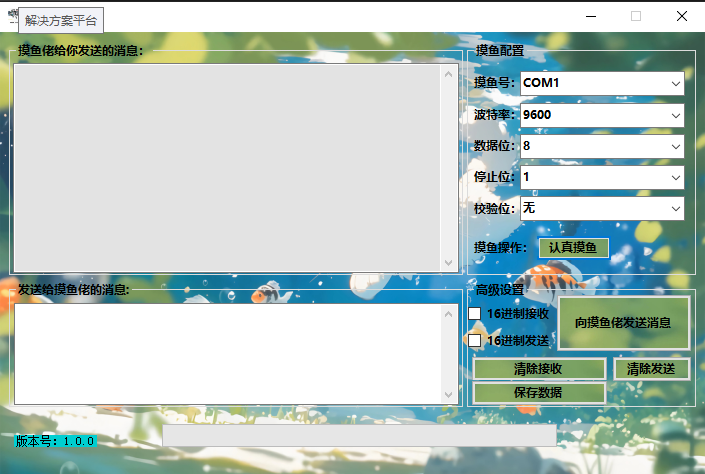
A great tool for slacking off in class - Bluetooth 2.0 chat.
Inspiration from the practice of teachers having their water and internet cut off all at once
Inspiration:
The inspiration for the usual system of cutting off water and internet access for all teachers came from a teacher who
needed to hand in their phone in the training room. Handing in their phone meant losing access to WeChat.
The plan was to create software similar to a serial port debugging assistant to communicate with a lower-level device, allowing them to contact others.
The PCB demonstration

module can be connected via an external HC05 Bluetooth connection.
"Slacking Off Assistant.exe.1"
Serial Port Debugging Assistant.zip
PDF_Classtime Slacking Tool - Bluetooth 2.0 Chat.zip
Altium_Classtime Slacking Tool - Bluetooth 2.0 Chat.zip
PADS_Classtime Slacking Tool - Bluetooth 2.0 Chat.zip
BOM_Classtime Slacking-Off Gadget - Bluetooth 2.0 Chat.xlsx
91747
SULILGH743_DX_STM32H743VIH6 flight controller
A flight controller based on the STM32H743VIH7 as the main controller, with multiple interfaces, multiple functions, and multiple firmware support.
Project Parameters
: Main Controller: STM32H743VIH6
; Gyroscope: 2 ICM42688_P;
Barometer: MS5611;
Magnetic Compass:
IST8310; : SD Card
; OSD: AE7456;
BEC: Supports 8S 12V1.5A 5V1.5A.
Hardware Details
: Main Controller: STM32H743VIH6; Frequency: 480MHz; Flash: 2048MB; RAM: 1024MB; Uses TFBAG100 package, can accommodate 0.45mm balls, relatively easy to solder with soldering skills
. Gyroscopes: Two ICM42688_P, allowing for more redundancy. Compared to the BMI088
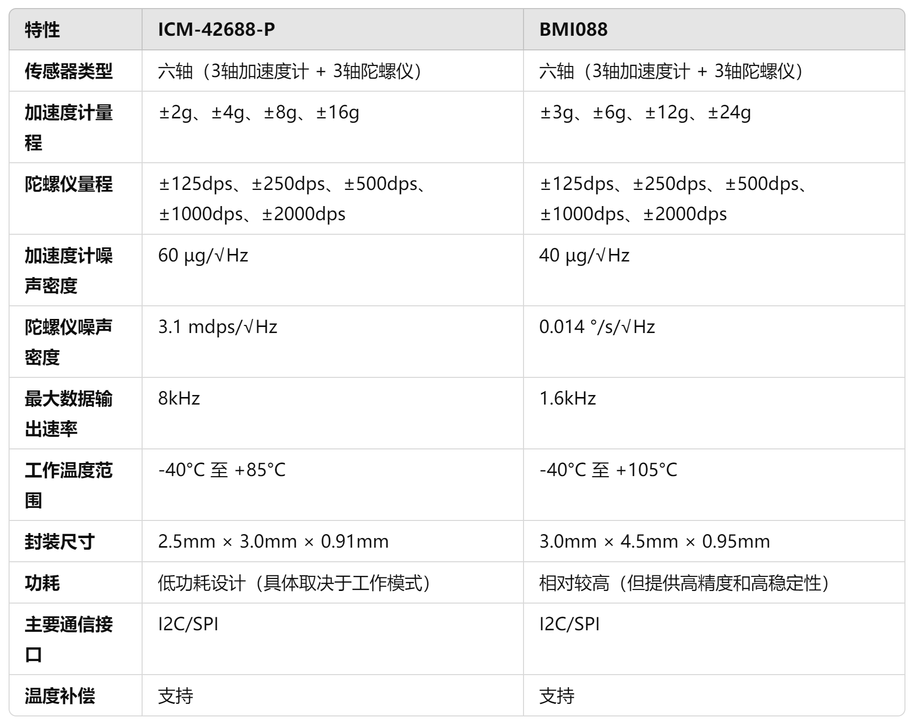
ICM-42688-P, the accelerometer noise density is approximately 60 µg/√Hz, and the gyroscope noise density is approximately 3.1 mdps/√Hz, giving it better performance in short-term angular velocity measurements
. Although its accelerometer has a lower noise density of 40 µg/√Hz, its gyroscope has a noise density of 0.014 °/s/√Hz, making it more accurate in measuring extremely low angular rates (such as small angle changes). However, its high noise density may affect accuracy under high dynamic conditions.
The ICM-42688-P has a data output rate of up to 8kHz, while the BMI088's maximum output rate is only 1.6kHz. A higher data output rate means the ICM-42688-P can capture more data points in a shorter time, thus providing more accurate measurements in fast-moving or high-frequency vibration scenarios. The response may also be more intense, potentially measuring more noise, so vibration damping is crucial.
**BEC: Uses MP4560 with an input voltage of 3.8V-55V.
** **LDO: LP5912: Quiescent current is 12 µA, which is very low among similar LDOs. The dropout voltage at full load (500 mA) is 120 mV. The LP5912 provides ±1% output voltage accuracy. The LP5912 has a PSRR of 70 dB at 1 kHz and maintains a high rejection ratio at higher frequencies (e.g., 10 kHz to 100 kHz). The LP5912's output noise density is 6.5. µVrms (10 Hz to 100 kHz) perform well in this type of LDO and are suitable for applications with stringent low-noise requirements, such as powering high-precision measurement circuits or noise-sensitive sensors. It uses two LP5912 chips, one for sensor power and one for main control power.
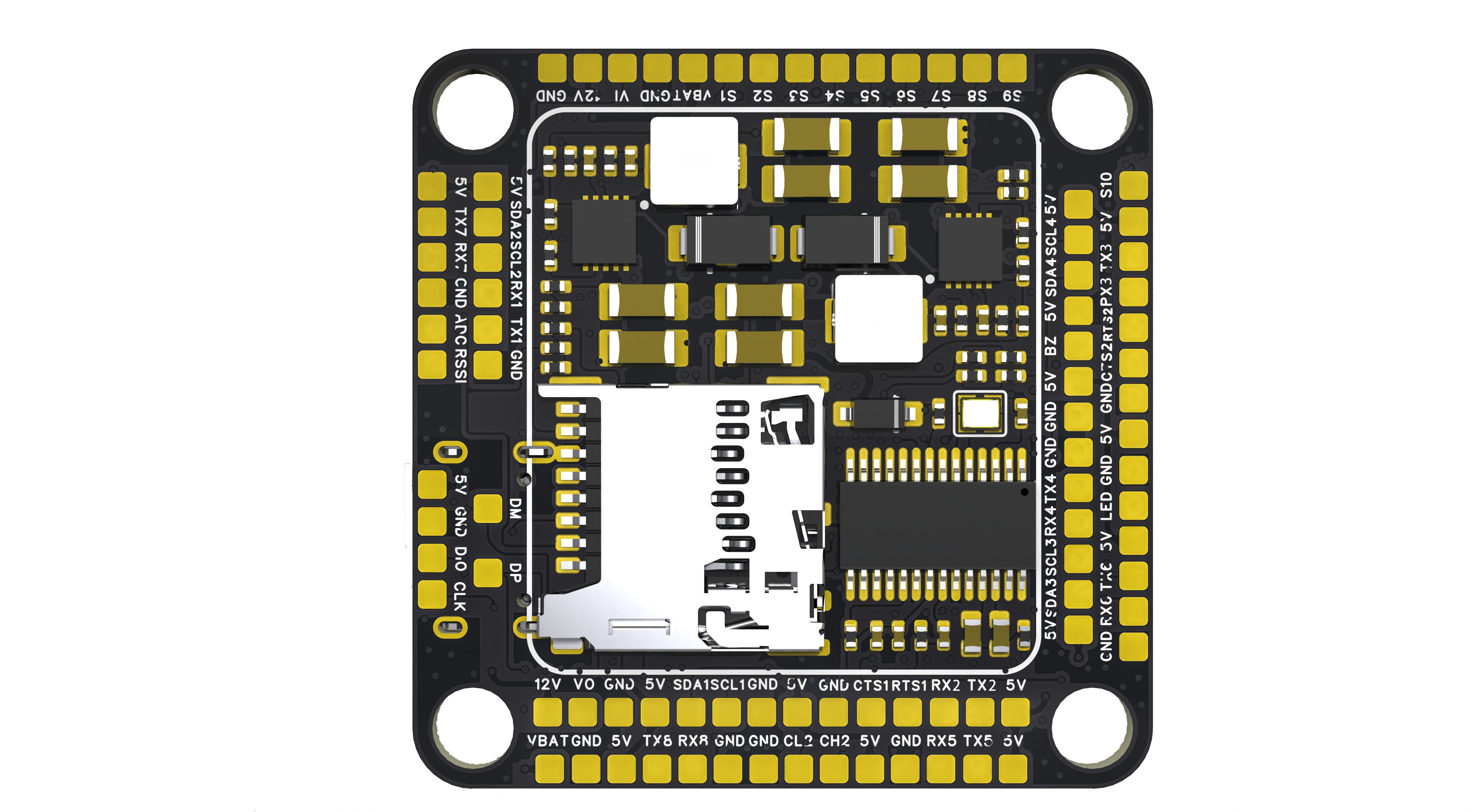
Functional interfaces
include: Serial ports: USART1, USART2, USART3, UART4, UART5, USART6, UART7, UART8 . The APM firmware adds synchronization functionality to the USART chip, making it an enhanced version of UART. USART functionality is only used in the APM firmware; other firmware uses UART
. The APM firmware adds USART_RTS and USART_CTS pin functions to USART2 and USART3, allowing connection to ESCs/data transmissions (cross-wiring is required). (This function is used for current limiting, controlling the amount of data sent via the serial port.)
RTS: Used by the MCU to notify the module whether the MCU is ready and whether the module can send information to the MCU. CTS
: Used by the module to notify the MCU whether the module is ready and whether the MCU can send information to the module
. I2C: I2C1, I2C2, I2C3, I2C4. I2C1 connects to the internal magnetic compass, but has solder pads for future connection.
PWM: S1-S10, plus an LED strip S11.
CAN bus: CAN1, CAN2. The CAN bus is an interface for connecting peripherals to the CAN bus under the APM firmware. Commonly used for connecting GPS devices, RTk devices, and galvanometers to the CAN bus, it can also be used as an expansion module for the CAN bus. This expansion module can connect serial devices, I2C devices, and SPI devices.
Analog image transmission: VI image input interface (connects to the camera signal line), VO image output port (connects to the image transmission signal line).
Analog input: CURR (for galvanometer analog signal input), RSSI (for signal strength input, generally used for receiver signal strength interface), and one unused ADC pin that can be configured to connect to an analog airspeed meter (3.3V analog signal, cannot be connected to 6.6V).
Debug interfaces: SWDIO, SWCLK, USB_DM_USB_DP.
[Rendering ,
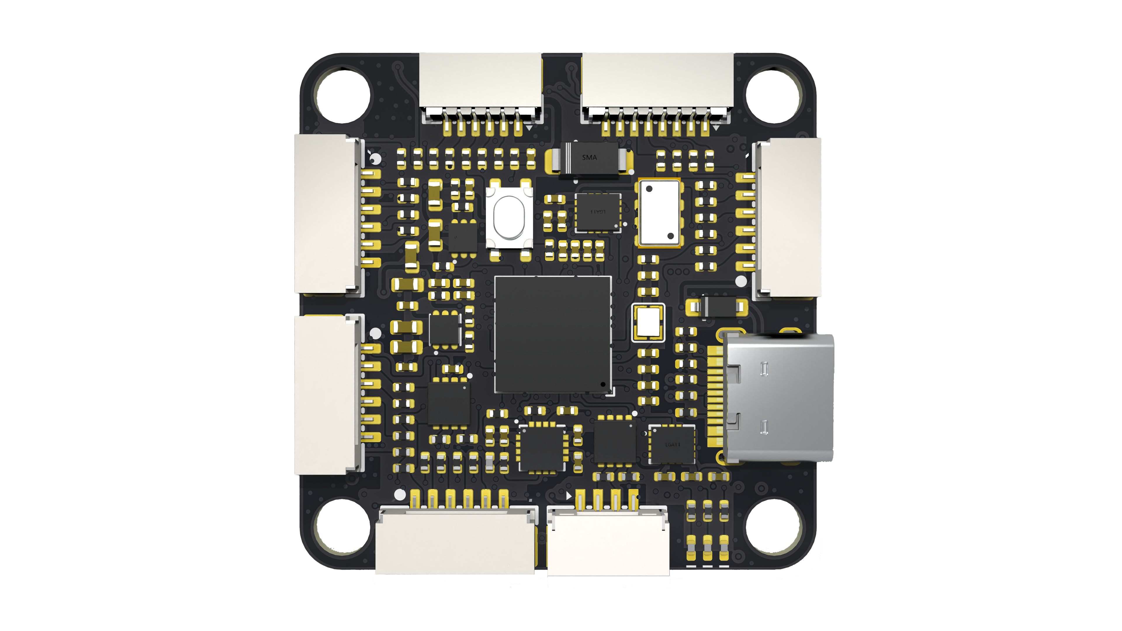
soldering effect,
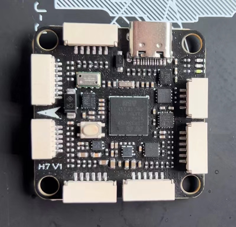
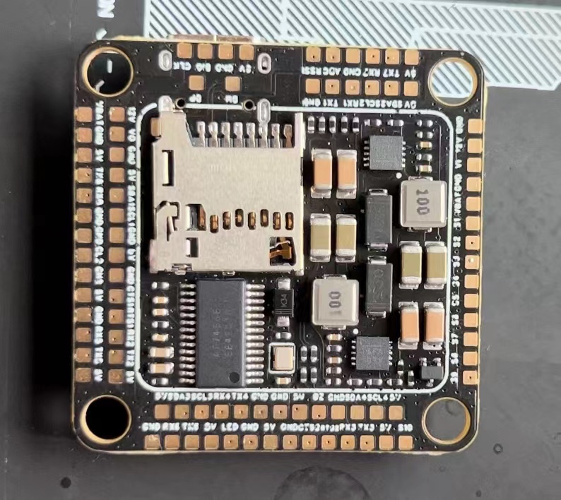
wiring diagram

] [For inquiries or commercial inquiries , please contact via

WeChat. Open source is not easy, thank you for your support. ]
SULILGH743_DX Flight Controller Data.rar
Indoor APM Firmware Manual Flight Video.mp4
PDF_SULILGH743_DX_STM32H743VIH6 flight controller.zip
Altium_SULILGH743_DX_STM32H743VIH6 flight controller.zip
PADS_SULILGH743_DX_STM32H743VIH6 flight controller.zip
BOM_SULILGH743_DX_STM32H743VIH6 flight controller.xlsx
91749
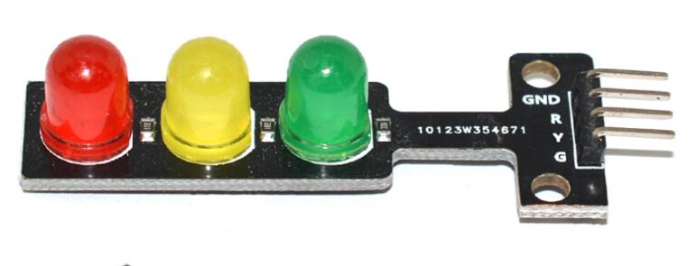
Traffic light module
Traffic light module
This is a simple traffic light module. A microcontroller outputs a high-level signal to control three individual LEDs. The circuit diagram is shown below.
Each LED has a current-limiting resistor.
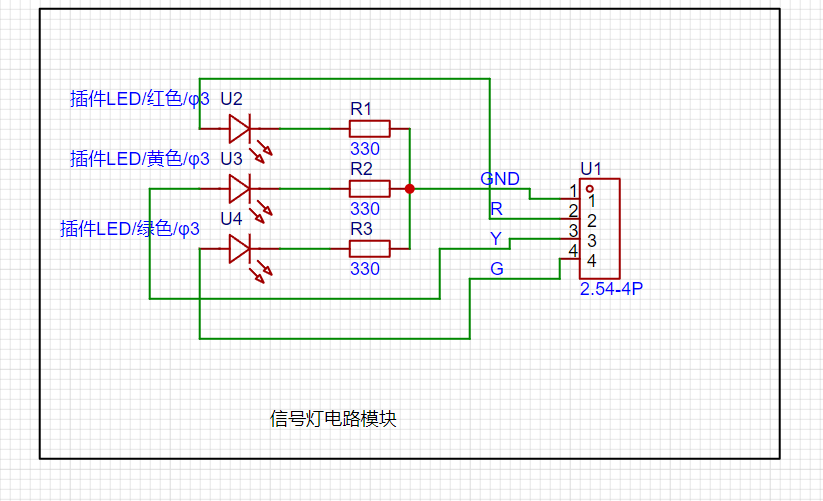
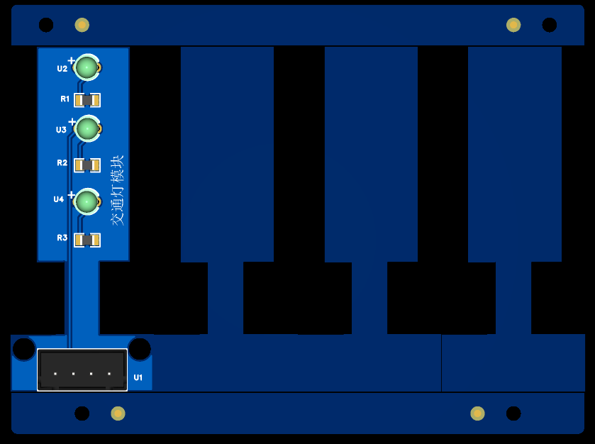
The actual circuit diagram is shown below.
The PCB uses panelization because each LED is a bit small.
Actual verification is as follows:


PDF_Traffic Light Module.zip
Altium_Traffic Light Module.zip
PADS_Traffic Light Module.zip
BOM_12.Traffic Light Module.xlsx
91750
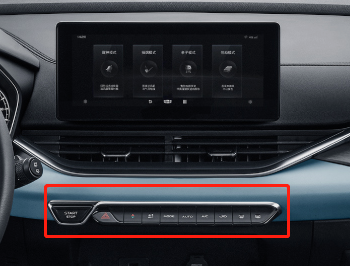
Car steering wheel multifunction buttons
Since I recently installed a Dingwei car infotainment system on my old Peugeot, but it doesn't have a multi-function steering wheel button, and Bluetooth buttons on Taobao are too expensive and don't look good, I made my own multi-function button that is compatible with most Android car infotainment systems.
Preface:
I recently installed a Dingwei car infotainment system on my old Peugeot, but it lacks multi-function steering wheel buttons and physical buttons. Controlling music while driving is difficult due to multiple inputs. Bluetooth buttons on Taobao are too expensive and unattractive, so I created a custom multi-function button compatible with most Android car infotainment systems.
The principle
is simple: the car infotainment system detects the resistance between two control wires, with different resistance values corresponding to different button functions (this is common for most Android car infotainment systems). Therefore, you only need to connect different switches to different resistors. For
the components,
I used a non-HiFi tactile switch, and then, inspired by a mechanical keyboard switch, I used one. I personally prefer tactile switches. The solder pads are compatible with most switches (I think), and it uses soldering (if hot-swappable is required, please modify accordingly and pay attention to the spacing). The keycaps are 18x23 and 18x18.
The outer
shell is 3D printed, giving it a piano key look, which I think is quite nice (note the temperature inside the car and the material's heat distortion temperature). It's directly glued under the car infotainment screen; I don't have a physical prototype yet.

~~I wanted to make something like this, but since I'm not aiming for mass production, I can forget about it...
This is
because the circuit board was obtained free, so the 8 buttons were split into two. However, the board can theoretically be expanded infinitely. The cascade pad in the image below is the expansion port, which is essentially two square control learning lines +12V. Simply connect the corresponding pads on the board you want to connect to. It
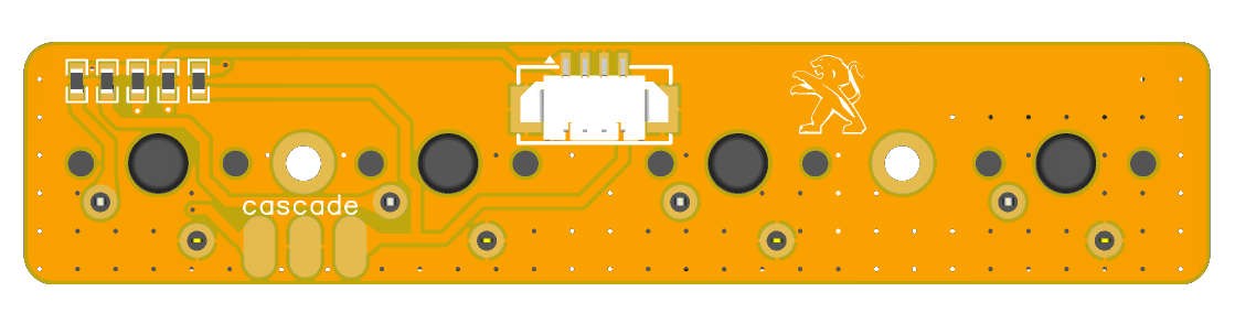
doesn't inherently need a 12V power supply; however, considering visibility while driving at night, a 12V ILL (the car's parking light detection line) was added. Turning on the headlights will activate the backlight (backlight brightness is selectable), controlled by the R5 resistor value.

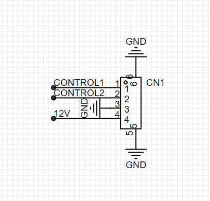
Wiring instructions:
CONTROL1-----> connect to square control learning line 1;
CONTROL2-----> connect to square control learning line 2
; GND------------> ground wire
12V-------------> connect to parking light detection line (ILL).
The board tests and functions normally. It works well for blind operation, eliminating the need to stare at the screen while driving.
Please drive safely!
Video_20230610162731.mp4
PDF_Car Steering Wheel Multifunction Buttons.zip
Altium_Car Steering Wheel Multifunction Buttons.zip
PADS_Car Steering Wheel Multifunction Buttons.zip
BOM_Car Steering Wheel Multifunction Buttons.xlsx
91751
electronic


 京公网安备 11010802033920号

 PT-3330B-HSA


