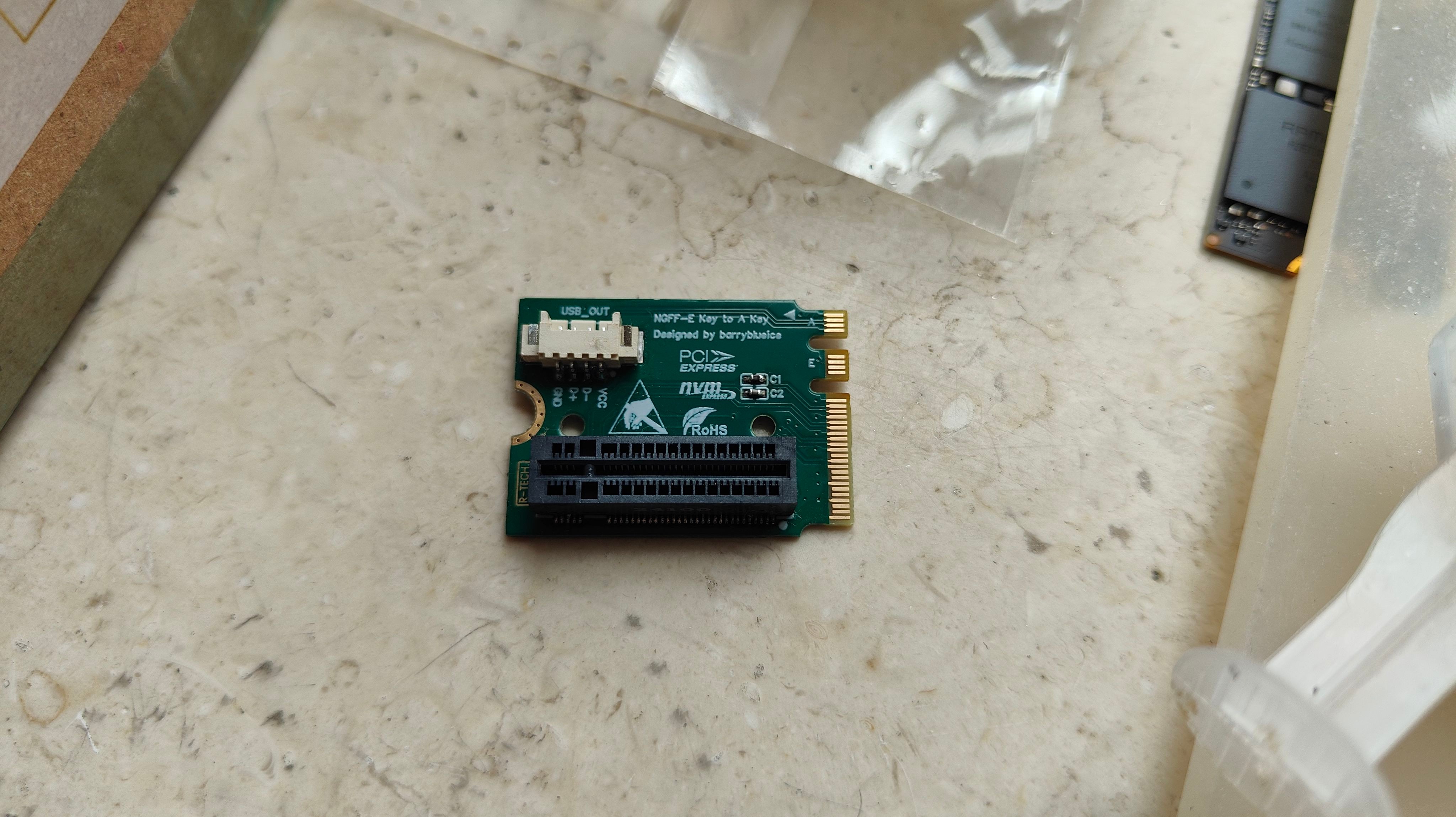
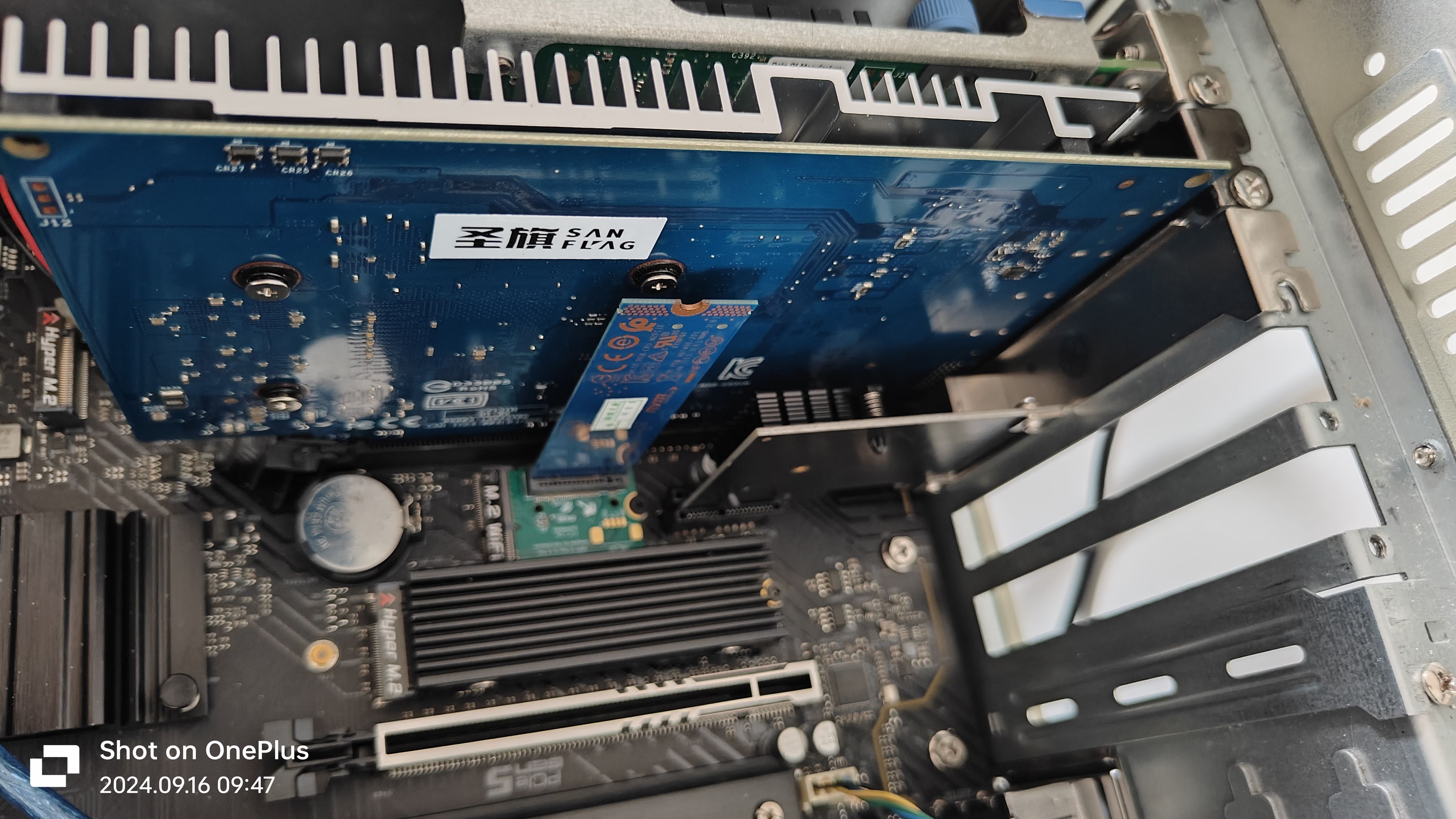
This was a project I made out of boredom. My ASRock H670 PG motherboard for servers has a really weak WiFi port, so I decided to make a vertical adapter to convert it to an NVMe SSD.
The SSD only uses the X1 routing definition, theoretically allowing negotiation up to PCIe 3.0*1 and backward compatibility.
The board has an MX1.25 USB port (originally for a network card and Bluetooth), which can be used with other USB devices.
Important notes:
CNVio interface is not supported. Please check if your motherboard's WiFi port supports PCIe network cards before use.
Please check if your motherboard's WiFi port natively supports Bluetooth. If Bluetooth requires an additional cable, the USB port will be unavailable.
Regarding design, prototyping, and manufacturing:
Updated 2024.11.10:
Four-layer board design with two complete ground planes, impedance control.
Designed with 50Ω single-ended impedance and 85Ω differential impedance. Effectively fixed the severe speed drop issue of the previous generation during large read/write operations (suspected to be caused by excessively loose impedance).
When customizing the PCB, you can use a four-layer free immersion gold coating voucher, 0.8mm thick. For impedance requirements, please select JLC04081H-3313.
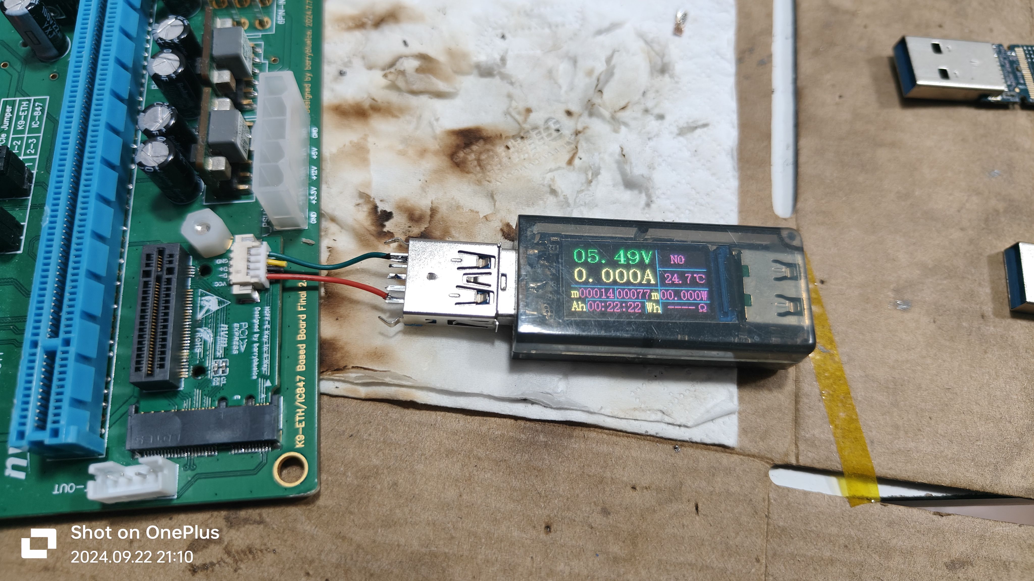
The USB 5V boost circuit uses SX1308, and actual testing shows it can output 5.5V.
The vertical NGFF M-key can be purchased from this store on Taobao or Alibaba.
There are two through holes on the back of the socket, which can be used for hard drive brackets (which can be made by yourself).
Currently compatible with:
ASRock H670 PG Riptide (I'm using it, tested and working)
, ASRock Z690 PG4 (same design as H670 PG Riptide, just different chipset),
Maxsun Z690 Terminator
...
Soldering demonstration (please be gentle with your soldering skills):
Front:
Back:

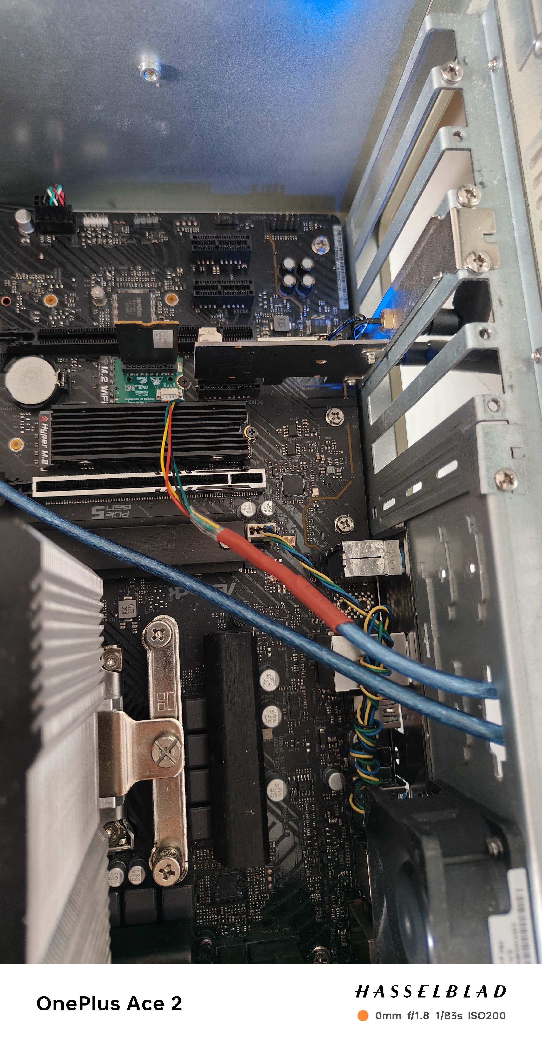
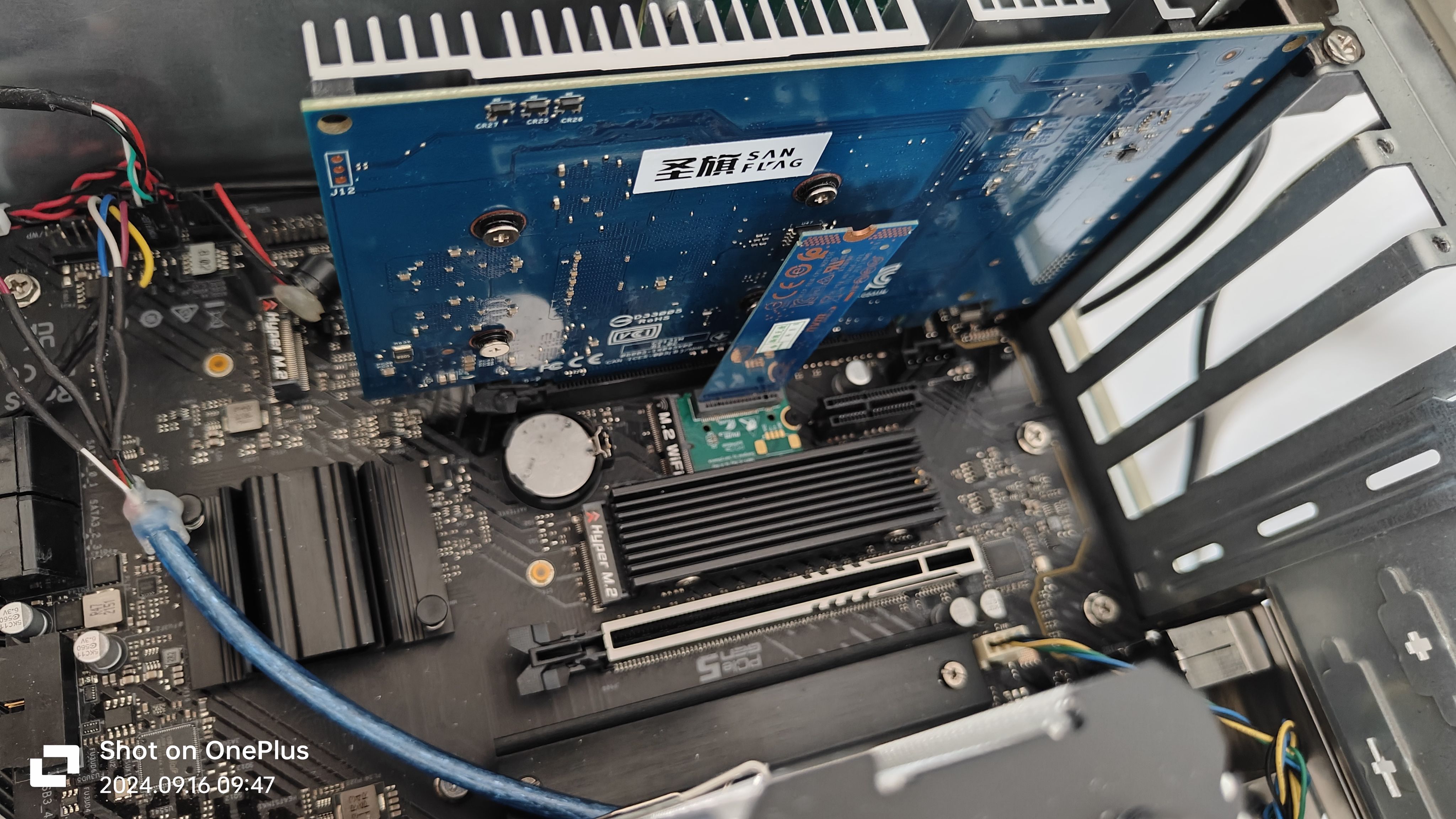
Physical compatibility test:
USB test:
Idle state:
Light load state:

Tested on-machine:
NVMe SSD test:
Hynix BC501 (2230 length):

Test with 2280 length Intel Optane 16G SSD:
Some smaller cards, such as RTL8125-BG expansion network card, are compatible under physical installation:
When replacing with a PCIe to four-port SATA expansion card, due to internal interface issues, conflicts may occur, so it is recommended to install some shorter length SSDs such as 2230, 2242, or smaller cards:

System test:
CPU: Intel® Core™ i3-12100F
Memory: 4 x Kingmax Silver Star Changxin DDR4 8GB 3600MHz
Motherboard: ASRock H670 Riptide
System: Windows Server 2025 for DataCenter 26100.1742
Test Hard Drive: Hynix BC501 256GB
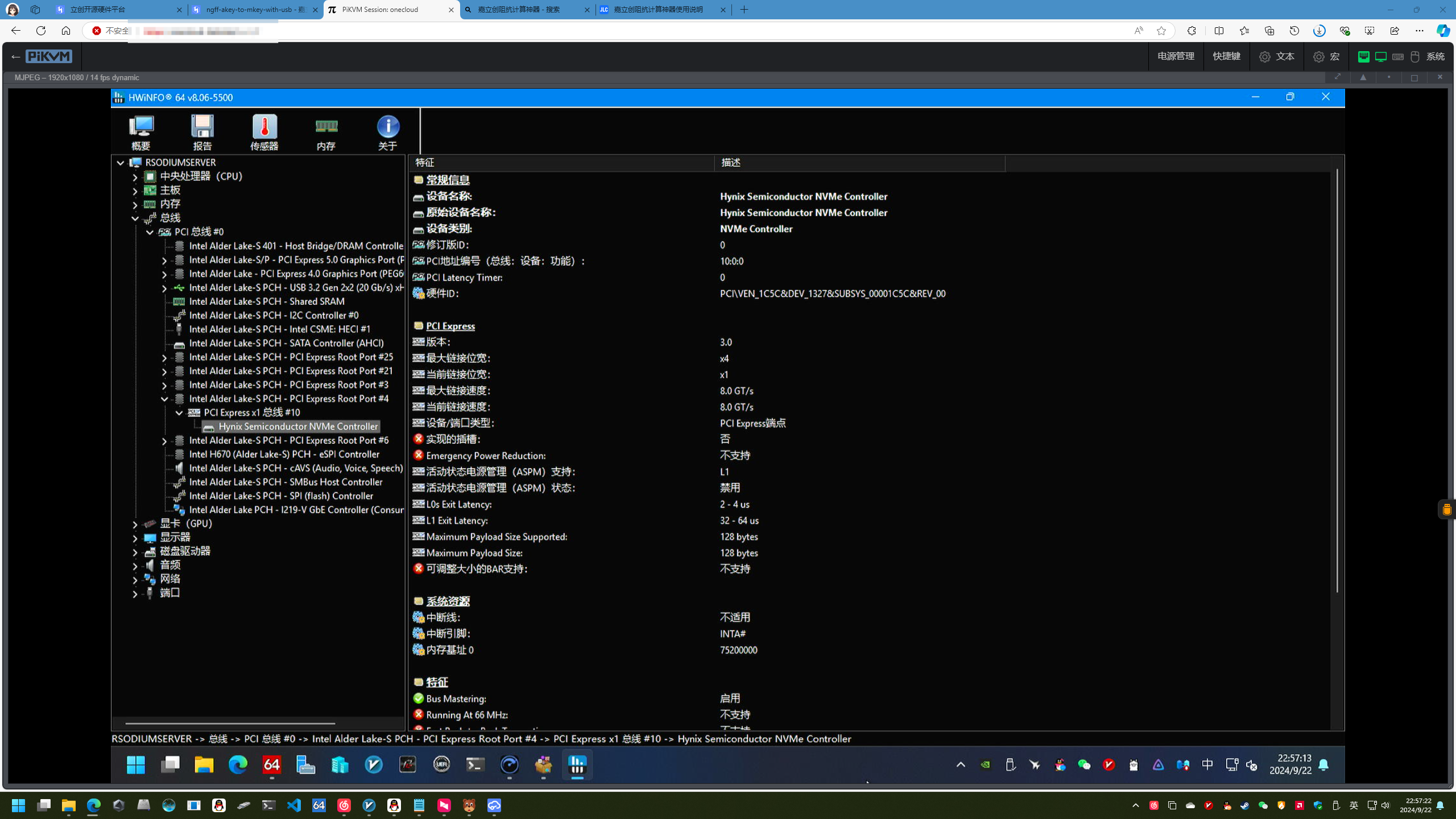
BIOS cannot recognize which NVMe drive it is, but it does recognize that it is an NVMe drive:

Crystal Disk Info, AIDA 64, and HWiNFO64 tests show that the BC501 has successfully negotiated PCIe 3.0*1:


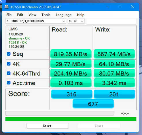
AS SSD speed test (test drive AM521):
BOM_PCIe-NGFF-A-Key to M-Key-Vertical Adapter for Cardboard USB_2024-11-10.csv
Gerber_PCIe-NGFF-A-Key to M-Key-Vertical Adapter for Cardboard USB_PCB_2024-11-10.zip
BOM_WiFi to NVMe, NGFF A to M-Key Vertical Adapter Card.xlsx
92056
[Verified] EV2400-Lite is based on F5528 [Replica not recommended]
The EV2400 battery debugger, based on the MSP430F5528, offers high cost-effectiveness and supports internal/external reference communication levels. Its USB interface and comprehensive communication port protection ensure reliable connection even if the device is damaged. As a BQ series battery protection chip, it's the ideal choice for unlocking DJI drone batteries.
Important Notes:
This project is geared towards sharing and exchanging experiences. Due to the following reasons, replicating this project is not recommended. If you do need to replicate this debugger or enjoy tinkering but don't want too much hassle, we recommend these two projects with fewer pitfalls: [Verified] EV2400-Economy Based on MSP430F5529 - LCSC Open Source Hardware Platform (oshwhub.com) and [Verified] EV2400-Lite Based on MSP430F5529 - LCSC Open Source Hardware Platform (oshwhub.com).
1. MSP430F5528 chips below 20 RMB on Taobao are almost never genuine; most are refurbished. My friend and I bought a total of 7 different MSP430F5528 chips from different sellers. Some couldn't be used after flashing the program, some couldn't access USB-BSL, some had no crystal oscillation, and some even didn't output VCORE voltage.
2. According to the advice of experts in the group, MSP430F5528 chips with disassembled boards from a certain online marketplace can be used. However, this marketplace is notorious for its mixed quality of vendors and unreliable practices. While it is indeed usable after testing, the success rate of replication cannot be guaranteed.
3. I personally purchased several MSP430F5529 LaunchPad development boards used in electronics design competitions. These boards include eZ-FET-Lite for programming the MSP430F5529, and the main controller is the 5528. This ensures they are official genuine products. However, I cannot flash the firmware using the EV2400 upgrade program in USB-BSL mode. The specific reasons are mentioned below.
4. Different system versions also affect the success rate of replication. The specific reasons are also mentioned below.
Schematic & PCB Design
1. This 2400 is the earliest version I wanted to create, but I encountered a lot of problems. After communicating with experts, I understood many issues and finally succeeded.
2. The schematic is modified from the official EV2400. @XDZZ suggested that the 5528 could replace the 5529, so the 5528 was used instead. The 5528 has all the main data exchange pins used by the EV2400, and both the 5528 and 5529 are from the same series with identical cores. The only difference is some peripherals and packages. The program files are fully usable.
3. The level conversion IC is slightly different from the one used by TI. TI's is harder to find, so a domestic one was used instead. The datasheet specifies a lower speed than the original, but it works fine in tests.
4. The PCB design is a bit large, mainly because I was too lazy to modify the casing model file and directly used a previously made casing.
Debugging & Firmware Flashing
1. After testing, most of the disassembled/cut MSP430F5528 boards (early stock) sold by sellers on Xianyu (a second-hand marketplace) can enter USB-BSL mode normally and can be recognized by the update software and complete firmware flashing. Since this project is mainly for discussion, please refer to the project: [Verified] EV2400-Lite Based on MSP430F5529 - LCSC Open Source Hardware Platform (oshwhub.com) for specific firmware flashing steps.
2. Use the eZ-FET-Lite programmer with UniFlash software to extract the firmware from the MSP430F5529 already flashed with EV2400 (the firmware is attached below) and flash it to the MSP430F5528 (requires the eZ-FET-Lite programmer, whose main controller is also MSP430F5528; I have also prototyped and open-sourced a version: [Verified] eZ-FET-Lite Debugger/Flasher - The process for using the LCSC open-source hardware platform (oshwhub.com) is as follows:
(Most of this text is copied from @hexesdesu, thank you!)
Find a programmer capable of programming the 5528 chip. The LaunchPad's onboard eZ-FET-Lite or FET430UIF will work. Connect it to the prepared board using the following connection method: SBW-RST --> RST; SBW-TST --> TEST; 3V3 --> 3.3V; GND --> GND.
Install the UniFlash tool on your computer.
Download the firmware package from the attachment; any of the three firmware options are acceptable.
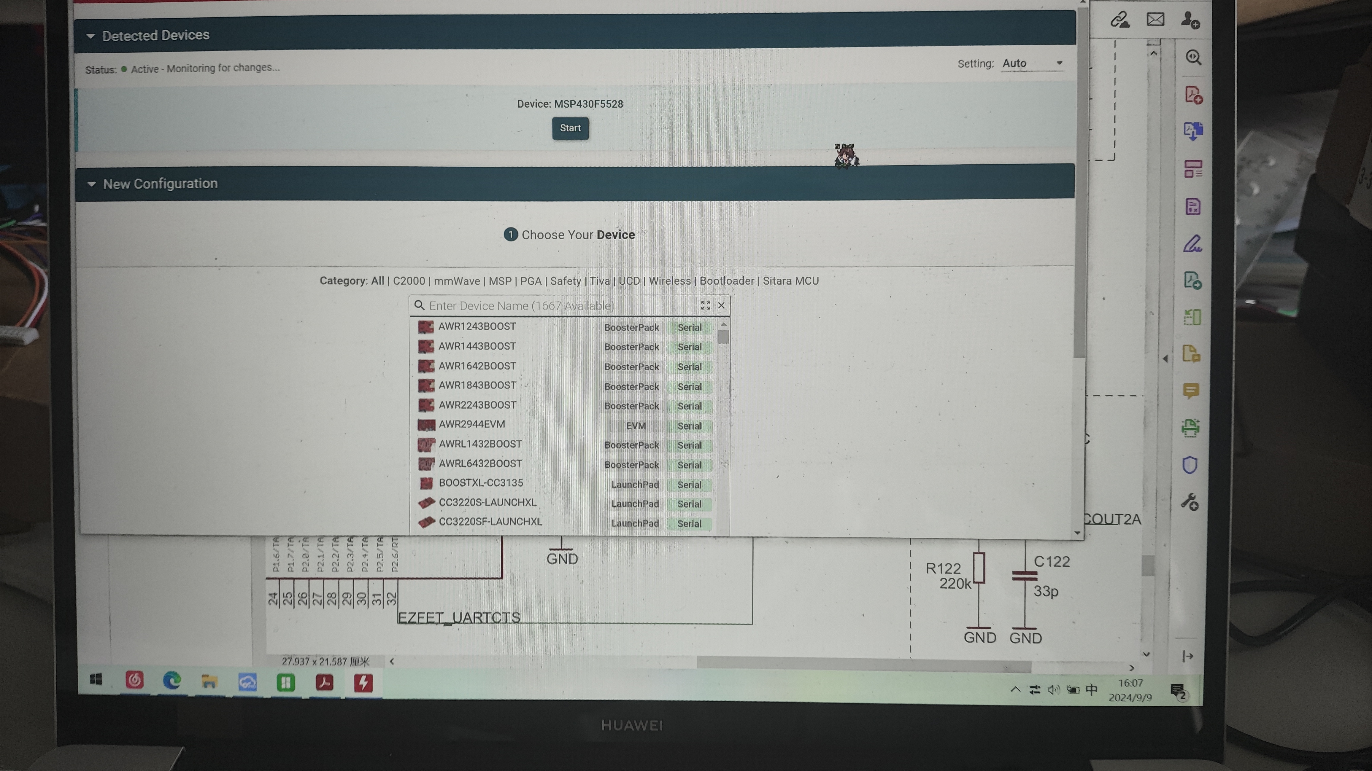
Open UniFlash, select the MSP430F5528 chip and connector. The first connector should be selected by default. (For the current version, there's an auto-detection option at the top. If auto-detection is enabled and the programmer is properly connected to the microcontroller, it will automatically recognize the target microcontroller. Just click on it (as shown in the image, simply click START to enter).)
On the Settings & Utilities page, find the Erase section and click Mass Erase. Wait for the erase to complete. (Do not click EraseByAddress. If you are using firmware with addresses 0x00-0x243ff or 0x4400-0x243ff as shown below, you can enter those addresses in Start and EndAddress to perform a full erase.)
In the Download section above, check Allow Read/Write/Erase access to BSL memory. Return to the Program page,
select the firmware you just copied in Flash Image(s), and click Load. After uploading the firmware to Image and waiting for a successful upload notification
, disconnect the burning cable and plug the EV2400-F5528 with the burned program into the computer. At this time, the three signal indicator lights will light up first and then go out, indicating that the computer recognizes the EV2400. The reported VID-PID is normal and can be recognized by the upgrade software.
3. The following describes the pitfalls encountered during the creation of this version and their solutions:
Homemade EV2400 debugger, problem-solving steps and cause analysis:
1. No response after plugging in USB and powering on:
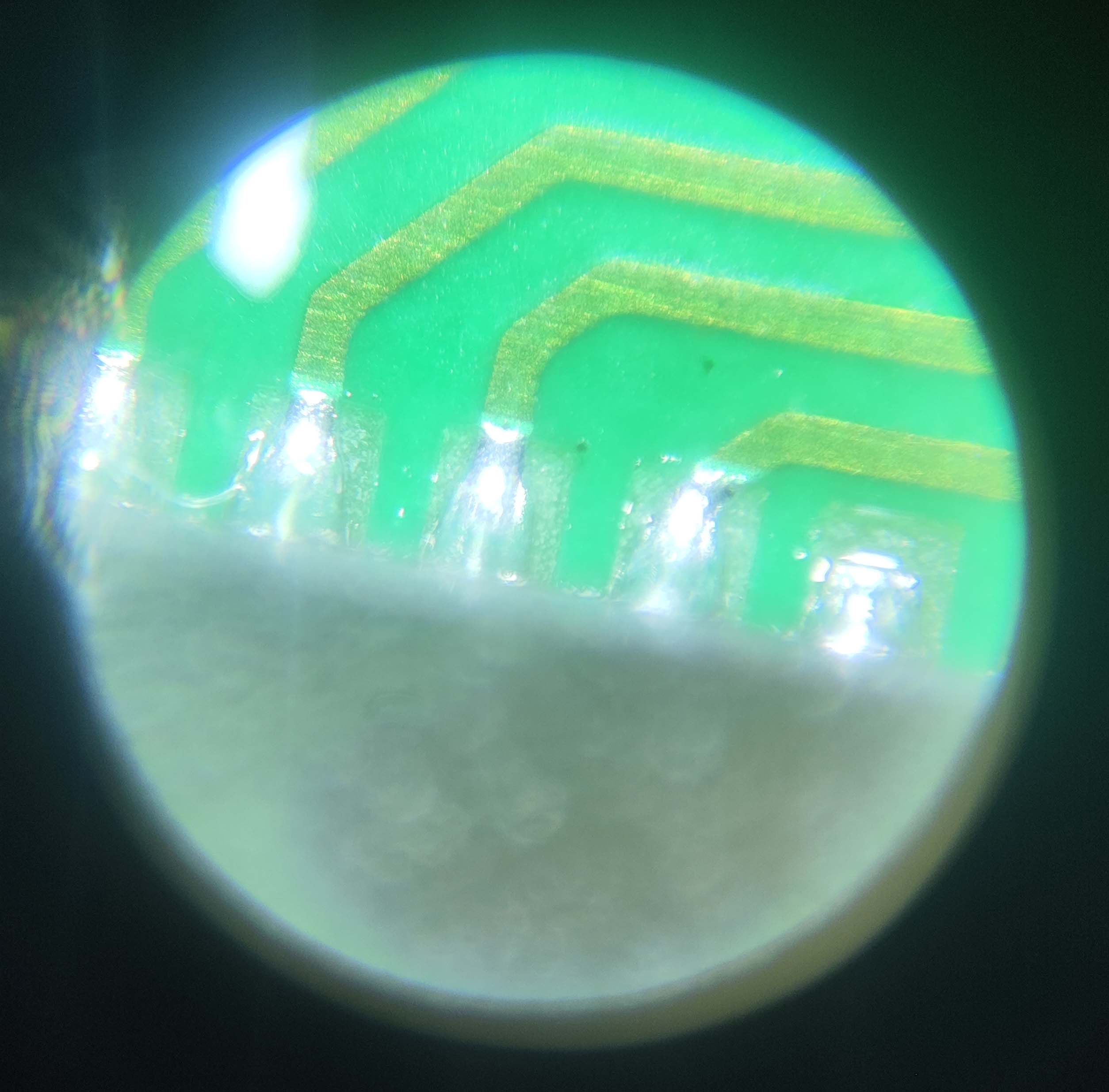
This is generally a soldering problem; 5529 is relatively easy to solder, but 5528 QFN is more difficult to solder, and LCSC's package is not a hand-soldered package, the exposed copper on the pins is very small, making it difficult to solder with a soldering iron. It is recommended to use a heating table + solder paste kit, and use a soldering iron to clean up excess solder balls and bridging. You can buy a monocular microscope for 20-30 RMB on Pinduoduo to check the pin status, which is quite useful (as shown in the picture).
After confirming that the soldering is correct, you can measure the voltage of the VCORE pin. It should normally be around 1.8V. If there is no voltage, congratulations, you have bought a defective chip. Quickly contact the seller to argue. If you bought it on Taobao, directly contact the official customer service to apply for a refund, on the grounds that you sold a scrap chip and the official software cannot recognize it. There is a high probability that you can get a refund.
If the VCORE has voltage, the crystal oscillator might not be oscillating. Don't believe any crystal oscillators on Taobao that claim to be genuine Murata parts. Crystal oscillators taken from the official MSP430F5529 LaunchPad development board work without matching capacitors. The ones I bought from Taobao, from three different vendors, all required load capacitors; otherwise, they wouldn't oscillate. The silkscreen markings were completely different from those on the official development board, so they weren't genuine.
If you have an oscilloscope to confirm oscillation, try shorting R6 for a long time while plugging the device into the computer's USB port. You should get a device insertion but not recognized message; otherwise, the USB connector's soldering or quality is faulty.
2. No device insertion beep on the computer (unable to enter USB-BSL mode).
If the USB interface soldering is confirmed to be fine after testing, the problem is usually due to improper shorting. This is my fault; it's difficult to short-circuit properly using the resistor pad method. I suggest using pointed tweezers, or using two wires to connect to a button. It could also be caused by excessive shorting time. Shorting only needs to be completed about one second after pressing the reset button. You can short-circuit first, then press the reset button, and release it for about one second before removing the shorting.
3. If you can enter BSL mode but the burning software crashes (the software doesn't recognize it),
this is because the software doesn't recognize the corresponding VID-PID. The reasons are as follows:
1. System issues (thanks to @3598abc). Try inserting the TYPC connector several times and use VID-PID detection software (attached). The PID and VID will change; sometimes VID0200 PID2047 is normal, and the LED will flash. The upgrade program and BQ software are normal. In a WIN7 32-bit system, both PID and VID will appear randomly (you can check the PID and VID in Device Manager). No issues were found on Windows 10 64-bit. Check the PID and VID in Device Manager. If the PID is 2047 and the VID is 0200 (LED flashing), it's normal. (The TYPC connector on the small board inserts normally when inserted slowly, but fails when inserted too quickly; I don't know why.)
2. Possible IC version issue. I bought several MSP430F5529 LaunchPad development boards used in the electronics design competition. They have eZ-FET-Lite for programming the MSP430F5529, and the main controller is 5528. This ensures they are official genuine products, but I cannot flash the firmware in USB-BSL mode using the EV2400 upgrade program. However, when I checked the official BSL manual, I found that the manual says the PID-VID reported by USB-BSL should be 2047-0200, but the actual test showed 2047-0203. Considering that the cases reporting usable USB-BSL are all early disassembled ICs, it may be because the firmware of the early ICs is different from that of the new ICs, or it may be because the LaunchPad has a BSL button for the 5529, and to prevent conflicts, the BSL firmware of the 5528 on the LaunchPad is a special firmware with a modified VID.
Currently, I'm considering reverse engineering the upgrade program provided by TI to modify the VID-PID to be recognized, thus enabling the flashing of various VID-PIDs.
A note at the end:
Nothing else is too complicated. If you encounter any problems, feel free to contact me for discussion; I'll reply as soon as possible.
The extracted firmware is attached, which you can flash directly. A VID-PID viewer is also provided to see where you're stuck. If you've read this far, please give it a like!
While writing this, I was thinking of flashing the BSL from the 5529 to the 5528, but it resulted in a 555 being locked (;´д`).
EV2400.txt
EV2400MIN.txt
EV2400MIN2.txt
VPidGetter.zip
3D_EV2400 Top Cover_2024-05-22 v2.3mf
3D_EV2400 bottom cover_2024-05-22 v2.3mf
EV2400-Lite-F5528-SOLVE.png
EV2400-Lite-F5528.psd
PDF_[Verified] EV2400-Lite Based on F5528 [Reproduction Not Recommended].zip
Altium_[Verified]EV2400-Lite based on F5528[Replica not recommended].zip
PADS_[Verified]EV2400-Lite Based on F5528[Replica Not Recommended].zip
BOM_[Verified]EV2400-Lite based on F5528[Replica not recommended].xlsx
92057
Desktop temperature and humidity measuring instrument
Make a simple desktop temperature and humidity meter
I. Project Overview
This project aims to design and implement a simple desktop temperature and humidity meter based on an STM32 microcontroller. This meter accurately measures the temperature and humidity of the surrounding environment and displays the data intuitively on a screen, providing users with real-time environmental information.

II. Hardware Components
STM32 Microcontroller: As the core of the system, it is responsible for data acquisition, processing, and control display.
Temperature and Humidity Sensor: A temperature and humidity sensor module is selected to accurately measure ambient temperature and humidity and transmit the data to the STM32.
Display Screen: A digital tube display is used to show temperature and humidity data and other relevant information.
Power Supply Module: Two AA batteries provide a stable power supply for the entire system.

III. Software Design
Driver Development: Drivers for the STM32 microcontroller and peripherals such as the temperature and humidity sensor and display screen are written to realize data acquisition and display.
Data Processing Algorithm: The acquired temperature and humidity data is filtered and calibrated to improve measurement accuracy.
Low Power Consumption Design: The software algorithm is optimized to reduce system power consumption and extend battery life.
Note: For physical verification, please see the video or attachments.
Displaying .mp4
PDF_Desktop Temperature and Humidity Meter.zip
Altium Desktop Temperature and Humidity Meter.zip
PADS Desktop Temperature and Humidity Meter.zip
BOM_Desktop Temperature and Humidity Meter.xlsx
92058
DSP28335_DIY
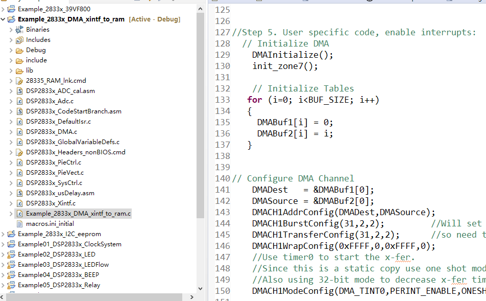
The DSP28335 development board has been verified for both SRAM and FLSAH.
This is a DSP28335 development board. The software engineers have done the wiring; the main requirement is that it works. The SRAM and FLASH have been verified. Other modules are basically functional.
PDF_DSP28335_DIY.zip
Altium_DSP28335_DIY.zip
PADS_DSP28335_DIY.zip
BOM_DSP28335_DIY.xlsx
92059
Intelligent tracking car
1. Suitable for driving at night or in low-light conditions.
2. Obstacle avoidance mode activated by a dedicated button.
3. Automatic obstacle avoidance.
4. Utilizes the HC-SR04 Bluetooth module to create a Bluetooth app in MIT App Inventor, enabling remote control of the smart car.
Remote Control Smart Car Video Link:
[Bilibili Video - Function Demonstration and Introduction] [Remote Control Smart Car] https://www.bilibili.com/video/BV1gvt2eCEtB/?share_source=copy_web&vd_source=b02d9189328fe7aeae112a7ea7982b01
I. Project Introduction
The car's MCU uses the Liangshanpai development board GD32F470ZGT6, which is powerful and has a fast response speed. Based on the teacher's training content, we developed independent buttons, ultrasonic sensors, and Bluetooth modules. We used basic Timer 5 and external interrupts for priority control to achieve multi-functional remote control. When the smart car encounters obstacles, the GD32F470ZGT6 microcontroller processes the data sent by the sensor module and combines it with the PWM wave. The processed data is then sent to the motor drive module for speed adjustment and direction control, while the power supply module provides a sufficiently stable voltage.
II. Project Functions
1. Can be used for driving at night or in low-light environments.
2. Obstacle avoidance mode can be activated using an independent button.
3. Automatic obstacle avoidance.
4. Using the HC-SR04 Bluetooth module, a Bluetooth app is created in MIT App Inventor to achieve remote control of the smart car.
III. Principle Analysis (Hardware Description)
This project consists of the following parts: power supply, LED lighting, motor, and Bluetooth. When the switch is turned on, the car is in a ready-to-command state. After turning on the phone's Bluetooth, a connection is established. If the light is dim, the lights can be turned on to control the smart car's forward, backward, and stop movements. Pressing the intelligent obstacle avoidance button or the car's independent button KESM will cause the car to automatically avoid obstacles. Alternatively, pressing KEYS will turn on the lights and trigger a buzzer.
Power Circuit:
When designing the power circuit, the overall operating voltage of the four-wheel drive car needs to be carefully considered. The GD32 core board operates at 5V, and the motor reference voltage is 6V; therefore, the power input voltage cannot be lower than 6V. Two 14500 potassium batteries were selected for power supply, with an operating voltage of 3.7*2=7.4V. The circuit design is shown in Figure 4.2.
P2 in the figure is the battery holder for the two 14500 batteries. After the batteries are installed, switch SW3 is turned on, and the power supply is regulated to 5V output by a linear regulator. C1 and C2 are power supply filter capacitors. LED10 is the power indicator, and R35 is the current-limiting resistor.
IV. Physical Image
[WeChat Image_20230817104906.jpg]

Remote control smart car.docx
Demo video.mp4
GD32F450.uvprojx
PDF_Smart Line-Following Car.zip
Altium_Intelligent Line-Following Car.zip
PADS_Intelligent Line-Following Car.zip
BOM_Intelligent Tracking Car.xlsx
92061
ESP32-based electronic musical instruments
An electronic musical instrument designed based on the button touch function of the ESP32 development board.
An electronic musical instrument designed based on the touch function of an ESP32 development board. It uses the `tone()` function to directly output a PWM wave from the GPIO port to drive an 8-ohm, 1-watt speaker. The ESP32's touch pins are brought out to pads as buttons, allowing for a stylophone-like function through touch by hand or a metal object. Audio can also be manually rewritten as a specific array of pitch and delay for playback within the microcontroller. Network connectivity allows for simple operations such as obtaining Bilibili follower counts. Further details are omitted
regarding the reserved serial port header, which may enable playback of array music from a computer via serial communication.
a341cfd4107d6efd80df443dfe8506b5.mp4
4060588e78ccfe88192db05807cc90f7.mp4
Play Canon.zip
Keyboard Piano.zip
PDF_ESP32-based Electronic Musical Instruments.zip
Altium_ESP32-based Electronic Musical Instruments.zip
PADS_ESP32-based Electronic Musical Instruments.zip
BOM_ESP32-based Electronic Musical Instruments.xlsx
92062
907 To T12 Handle Stand - On-Hole Sleep
DIY a T12 soldering iron handle that supports standby and sleep mode.
I directly replicated a T12 soldering iron using an open-source solution found online (https://github.com/wagiminator/ATmega-Soldering-Station), specifically version V1.7. The
existing sleep mode implementation using Arduino employs a vibration switch to detect handle vibration, with the main program supporting a minimum time of one minute.
This one-minute inactivity timeout seems excessive to me, and the vibration switch isn't very sensitive.
Therefore, I designed a new soldering iron stand that is compatible with the original design. I added an STC8G microcontroller and an SC7A20TR accelerometer to the handle to detect its movement,
improving sensitivity.
I slightly modified the main program, adding a quick sleep menu, "QC Sleep Timer," which allows setting the sleep timeout from 0 to 60 seconds (0 for off).
This way, when you put the soldering iron down, it quickly enters sleep mode after the set number of seconds.
Principle: When the sensor in the handle detects movement, the microcontroller inside the handle repeatedly changes the level state of SW to notify the main controller.
Arduino uses ISP to program and write the EEPROM without erasing (retaining) the file
SolderingStation2_u8glib_v1.7.ino.hex without erasing the EEPROM
. Attachments:
SC7A20TR hibernation program.hex, handle vibration detection program (STC8G series microcontroller),
SolderingStation2_u8glib_v1.7.ino, soldering iron host control program (Arduino development environment).
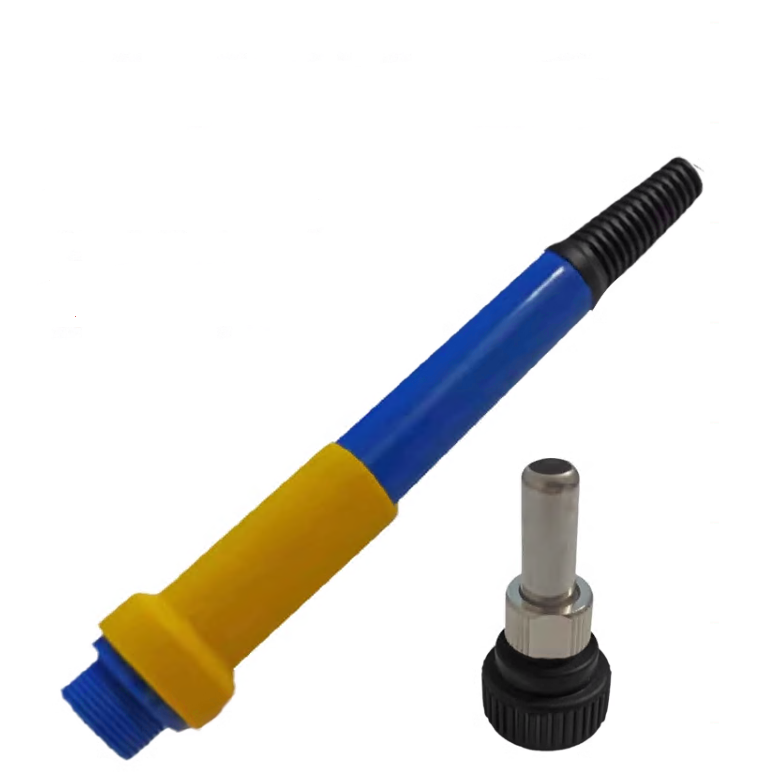
Materials needed:
1. One blue handle as shown in the picture (you can buy the handle separately (two parts shown).
2. Soldering iron contact springs

. 3. Approximately 1 meter long five-core cable (I used a 5-core aviation plug; pay attention to the outer diameter of the wire, otherwise it may not be possible to install). 4. Prepare the gamepad program for
electronic components according to the PCB diagram : Please refer to the STC official documentation. Use a USB to serial port tool to connect to the TX and RX pads reserved on the bracket PCB, and ground the program from the GND pad. This will allow you to successfully program the SC7A20TR rack-mount sleep program. (hex gamepad test video)
SC7A20TR Hibernation Program Available.hex
Test video.mp4
SolderingStation2_u8glib_v1.7.ino.hex
PDF_907 To T12 Controller Stand - Up and Go to Sleep.zip
Altium_907 To T12 Controller Stand - Up and Sleep.zip
PADS_907 To T12 Controller Stand - Ready for Sleep.zip
BOM_907 To T12 Handle Stand - Mount to Sleep.xlsx
92063
Mini_ODrive_AT32F435_42*42
The streamlined and optimized version of OFad has an overall cost of around 50 (onboard encoder). The main controller uses AT32F435, with a 24kHz current loop and an 8kHz speed and position loop, supporting both sensored and sensorless operation.
This document introduces
a streamlined and optimized version of ODrive, with an overall cost of around 50 (including the encoder). The main controller is an AT32F435, featuring a 24kHz current loop and an 8kHz speed/position loop. It supports both sensored and sensorless operation, with sensored support for MT6816, MT6825, MT6835, and AS5047P via SPI mode.
The code is primarily based on the latest version of ODrive, with secondary development and porting. It also includes ported VESC's observer and automatic open-loop components, MIT's encoder nonlinearity compensation (1024 points), and numerous optimizations and additions.
The host computer is mainly based on the ui_odrivetool project, with reference to some code from SimpleFOCStudio and VESC Tools.
Performance Parameters:
Voltage Input: 8-24V (2S-8S)
Temperature: -10-85℃
Peak Power: 240W
Control Rate: Speed/Position Loop 8kHz, Current Loop 24kHz
PWM Switching Rate: 24kHz
288MHz 32-bit AT32F435 Microprocessor
Peak Phase Current: 12A
Maximum Electrical Angular Velocity: 120000 ERPM
Size: 42*42mm - CAD Drawings/STEP Files
Communication: 1Mbps CAN or 115200bps UART
Reference Project Addresses:
https://github.com/odriverobotics/ODrive
https://github.com/vedderb/bldc
https://sourceforge.net/projects/phobia/
https://github.com/mjbots/moteus
https://github.com/bgkatz/motorcontrol
https://gitlab.com/p87942130/ui_odrivetool
https://github.com/JorgeMaker/SimpleFOCStudio
https://github.com/vedderb/vesc_tool
Related tutorials: https://www.bilibili.com/video/BV13XtseQEb3/
(This version is for group members; the open-source hardware is for reference. Firmware and host computer can be obtained by joining the group @ContradictionAggregator)


Notes:
This project only provides the packaged host computer file (.exe) and compiled firmware (.hex). The software part is not open source, please don't keep asking in private messages.
When soldering, note that the silkscreen of GS4157B-CR is very small, and a magnifying glass may be needed to assist soldering. Of course, it's okay not to solder it, but some functions will be lost.
The main controller uses a 288MHz AT32F435, and the power consumption and temperature are relatively high during operation, which is normal (estimated by hand to be about 40°C, no-load power consumption 0.8W).
The recommended MOSFET is WSD4070, and a 10-ohm gate resistor can be used. If other MOSFETs are used, the gate resistor may need to be replaced.
This project uses the RS724 op-amp, which is relatively expensive. You can choose a cheaper option like the RS624, a 4-channel op-amp that is pin-to-pin compatible.
The LP5907 requires a 3.3V power supply; make sure you buy the correct one.
For the dissipation circuitry, you can selectively solder it as needed; it's not mandatory.
I recommend buying the WS2812B RGB LED from Taobao. Different manufacturers produce these LEDs with significant differences, which may result in reversed red and green colors or random flashing.
The FD6288 on Taobao for 1.5 RMB is a used product; a brand new, original FD6288 costs 2.5 RMB or more.
That's all I can think of for now; I'll add more later.
PDF_Mini_ODrive_AT32F435_42_42.zip
Altium_Mini_ODrive_AT32F435_42_42.zip
PADS_Mini_ODrive_AT32F435_42_42.zip
BOM_Mini_ODrive_AT32F435_42_42.xlsx
92064
electronic


 京公网安备 11010802033920号

 1200HG3F019A3LA


