Key Features
: Core: ARM Cortex-M4, clock speed up to 240MHz, supports FPU and DSP instruction sets.
Storage: Supports 1024K Flash (zero-wait memory execution) and 224K SRAM.
Peripherals: Includes 3 12-bit ADCs, 8 general-purpose 16-bit timers, 2 general-purpose 32-bit timers, 2 PWM timers, 2 16-bit basic timers, 1 RTC timer, 3 I2C interfaces, 4 SPI interfaces (can be reused as I2S interfaces), 2 SDIO interfaces, 8 USART interfaces, 1 SPIM interface (can be expanded to 16M program or data), 1 USB interface and 2 CAN interfaces (USB+CAN can be used simultaneously), 1 external storage controller XMC interface (static RAM, NAND, parallel LCD), 55 I/O ports, 14-channel DMA, and Slib security library.
Package: LQFP-48
Operating Temperature Range: -40°C to +105°C
Supply Voltage: 2.6V to 3.6V
Core Board Features:
Reserved external SPIM Flash up to 16M (W25Q128)
API library read/write capability, encryption supported
Code can be run in external Flash
One user LED
One user button
System reset button
BOOT mode selection
SWD download port (supports DAP Link, J-Link, AT Link)
Serial port USART1 (below the SWD interface)
Linear regulator 500mA Max
Compatible with commercially available STM32F103C8T6 core boards (including GPIO pin distribution and dimensions)
Physical display

Classic pin interface
structure and dimensions
AT32F403ACGT7 classic pin interface diagram.pdf
AT32F403ACGT7 classic pinout diagram.png
AT32_Project.zip
AT32F403ACGT7 core board data package.zip
PDF_AT32F403ACGT7 core board (compatible with C8T6 core board).zip
Altium_AT32F403ACGT7 core board (compatible with C8T6 core board). zip
PADS_AT32F403ACGT7 core board (compatible with C8T6 core board). zip
BOM_AT32F403ACGT7 core board (compatible with C8T6 core board).xlsx
93087
Digital Meter Training Camp
A simple and practical digital electricity meter
A simple and practical digital meter
incorporates a voltage reference chip. The core of the 431 microcontroller is an operational amplifier (op-amp) that acts as a comparator in the circuit. Internally, the chip has a voltage Vref (approximately 2.5V), which acts on the inverting input of the comparator. The non-inverting input of the comparator receives a voltage input to REF. When this voltage is greater than Vref, the comparator outputs a high level, enabling a transistor and connecting the CATHODE (cathode) and ANODE (anode) terminals. If REF and CATHODE are at the same potential (connected together), the potential at REF is pulled low. When the potential at REF drops below Vref, the comparator outputs a low level, the transistor turns off, and the potential at REF rises back up. When it rises above Vref, the process repeats. Because the hardware response speed is extremely fast, the voltage at REF is almost equal to Vref.
Digital voltmeter and ammeter with calibration function.zip
PDF_Digital Meter Training Camp.zip
Altium Digital Meter Training Camp.zip
PADS Digital Meter Training Camp.zip
BOM_Digital Meter Training Camp.xlsx
93088
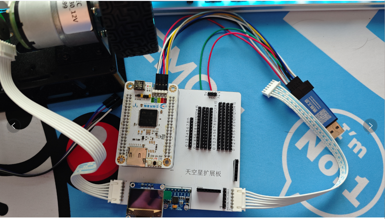
Sky Star Car Expansion Board
I bought several SkyStar development boards during a SkyStar promotion, and since I already had wheels for a balance car, I decided to build a SkyStar balance car. During the construction process, I noticed the DuPont wires were a bit messy, so I ended up with this expansion board.
I. Introduction to the Skystar Development Board
Skystar Development Board Schematic Diagram:

II. 0.96-inch I2C Screen Interface and 0.96-inch SPI Screen Interface

III. MPU6050 Interface
IV. Bluetooth Interface
V. All Pins Present

PDF_SkyStar Car Extension Board.zip
Altium_SkyStar Car Expansion Board.zip
PADS_SkyStar Car Expansion Board.zip
BOM_SkyStarCarExtensionBoard.xlsx
93089
STC32G12K128 Development Board
Development board based on STC32G12K128-LQFP48 chip
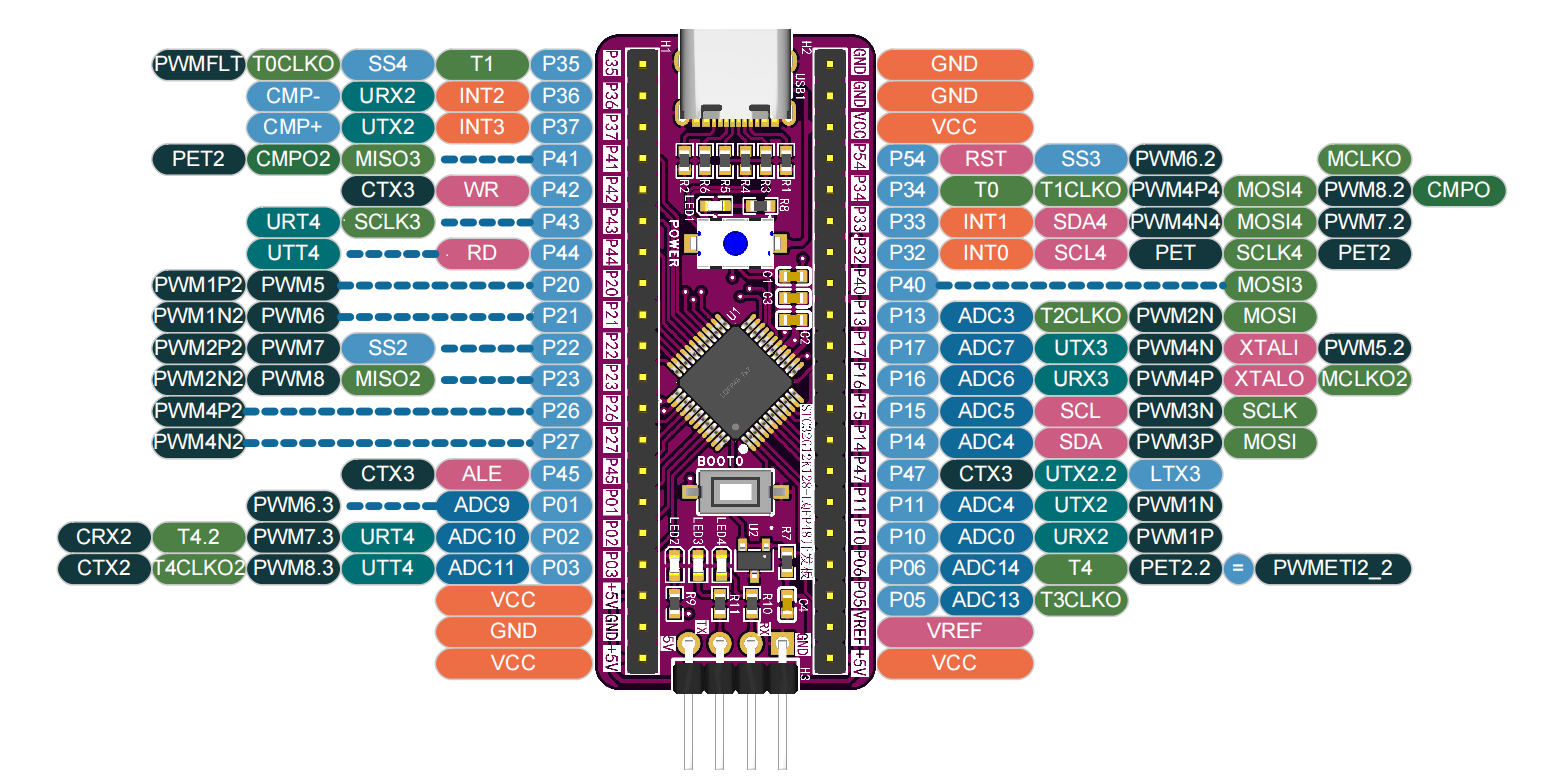
I. Development Board Pin Function Diagram
II. Onboard Components
Main Control Chip: STC32G12K128-LQFP-48
Power Connection: Powered by one Type-C port or connected to a computer for program download
LED Display: One power indicator, one test indicator, and two program download indicators
Button Control: One normally closed switch (POWER) for cold start download, replacing the RESET button; one independent button with interrupt function (BOOT0)
Program Expansion: An external M24C20 EEPROM chip (designed on the back of the development board) is connected via an IIC interface Pin
Header Interface: Two rows of 20-pin 2.54mm headers are used to bring out all chip pins, compatible with the pin arrangements of other mainstream microcontroller core boards; a header interface for connecting a programmer/debugger is reserved on the back of the development board.
Reference Voltage Source: A CD431 reference voltage source is used to provide a stable 2.5V reference voltage for the microcontroller (optional; 5V is provided when not soldered).
III. Other Instructions
This development board does not have an onboard serial port chip; instead, it uses the built-in USB-HID function of the main control chip to connect to the computer for downloading.
The download method is as follows: Connect the computer and the development board using a Type-C cable, press and hold the BOOT0 button, then press the POWER button to power on again. When you see the green LED light up, release the BOOT0 button; you have now entered download mode.
The download attachment provides a program for flashing the onboard LED2 (blue light) for testing the development board.
STC32G12K128_LQFP48 Demo Video and Program.rar
STC32G12K128-LQFP48 Development Board Verification Video.mp4
PDF_STC32G12K128 development board.zip
Altium_STC32G12K128 development board.zip
PADS_STC32G12K128 development board.zip
BOM_STC32G12K128 development board.xlsx
93091
J-Link BASE V9 (Jlink V9)
J-Link Base V9
Attention!!!
Select 7628 stack-up.
The project
uses a generic housing with a Type-C interface and provides a Vref/3.3V power switch (an indicator light will illuminate when switched to 3.3V).
Remove the RTCK signal cable.
Note:
Special note: H1 in the BOM is unnecessary. Purchase an 8.35mm Type-C adapter; standard ones will be slightly recessed.
The Type-C interface requires enlargement. The switch also needs additional drilling depending on the situation (if switching is infrequent, the switch can be removed; one of the case and graphics card will always need to be removed).

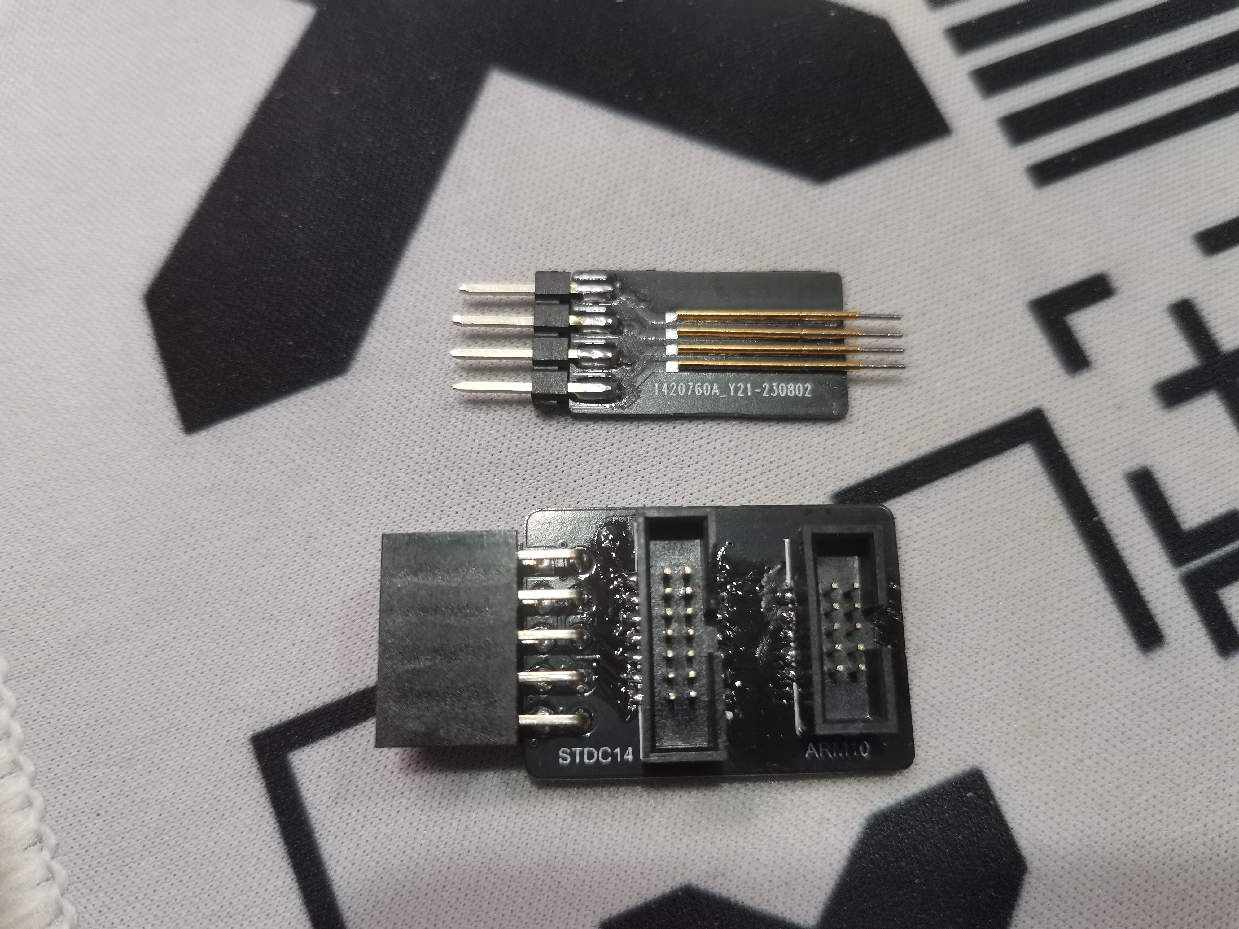
Download requires 1.27mm pitch probes; the adapter provides 1.27mm 2x5 and 2x7 adapters, as shown in the image.
PDF_J-Link BASE V9 (Jlink V9).zip
Altium_J-Link BASE V9 (Jlink V9).zip
PADS_J-Link BASE V9 (Jlink V9).zip
BOM_J-Link BASE V9 (Jlink V9).xlsx
93092
electronic


 京公网安备 11010802033920号

 TM4C1237H6PGEI7


