The charging section uses the TP4056 as the charging chip, which is reliable, inexpensive, and has a simple peripheral circuit.
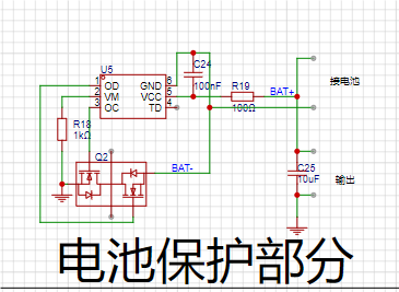
The battery protection section uses the DW01A chip, a common battery overcurrent and overvoltage protection chip on the market.
The charging section uses Type-C power supply. It uses a plug-in 4-pin Type-C interface, which is inexpensive.
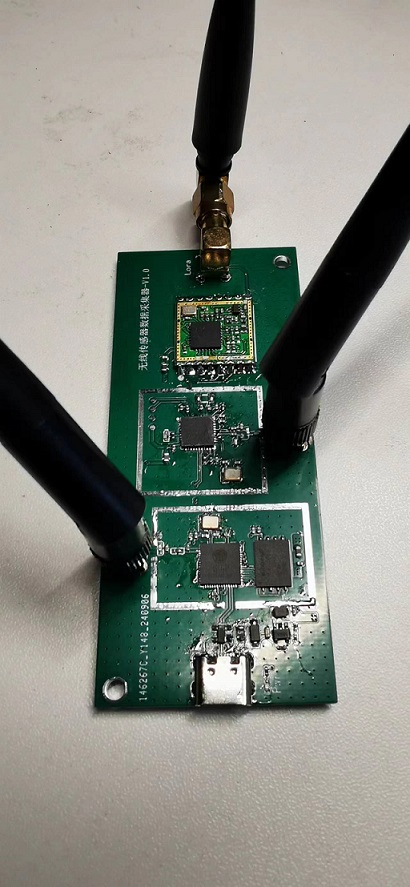
Data from the zigbeelora sensor is collected via ESP32 and uploaded via Wi-Fi.
Data from Zigbee and LoRa sensors is collected via ESP32 and uploaded via Wi-Fi.
The Zigbee module is the CC2530,
and the LoRa module is the SX1278. The design incorporates both modules for compatibility.
Shielding covers are provided for all three wireless modules.
PDF_IoT Data Acquisition Device.zip
Altium_IoT Data Acquisition Device.zip
PADS_IoT Data Acquisition Device.zip
BOM_IoT Data Acquisition Device.xlsx
92299
F407 Extended Learning Board
STM32F407VGT6 Expansion Edition V1.0, compatible with GD32F407VET6 LCSC SkyStar Development Board
This expansion board includes commonly used modules, communication protocols, and input/output interfaces,
primarily including:
a common LCD display, a Taojingchi serial port screen
, ADC acquisition, buttons,
WS2812B three-color LEDs,
an SG90 servo motor
, a DHT11 temperature and humidity sensor, a potentiometer
, a buzzer, a rotary encoder,
I2C, UART, and PWM output interfaces
, DC socket power supply, and 5V, 3.3V, and 1.65V outputs.
Detailed specifications:
All pins are led out via pin headers and are silkscreened;
the I2C interface OLED includes both new (starting with GND) and old (starting with VCC) versions; be careful not to plug them in incorrectly;
the AD acquisition interface uses an RF coaxial connector for easy connection and fixation, and can be replaced with wires to reduce costs;
the WS2812B three-color LEDs can meet common lighting needs;
temperature sensor, potentiometer, and rotary encoder provide multiple analog signal acquisition methods;
5V development board TYPE-C power supply;
additional notes:
the attachment includes the initialization HAL library project for the interface modules (to be open-sourced after completion);
PDF_f407 Extended Learning Board.zip
Altium_f407 Extended Learning Board.zip
PADS_f407 Extended Learning Board.zip
BOM_f407 Extended Learning Board.xlsx
92301
F407VET6 Expansion Board
This project is a peripheral interface board designed for the STM32F407VET6 development board, providing a variety of interfaces and functional expansions to meet different development needs.
This specification
supports STM32F407VET6, STM32F407VGT6, and GD32F407VET6
. It offers rich peripheral interfaces including motor drive modules, buzzers, servos, rotary encoders, and temperature and humidity sensors
. Multiple communication interfaces are available, such as USART, SPI, and I2C
. Expansion pins include GPIO and ADC interfaces
. Onboard power management includes power indicator lights and a power switch.
All pins are brought out via headers.
Important notes:
Ensure secure and reliable soldering.
Before powering on, check for cold solder joints and ensure the power supply voltage meets requirements.
Follow the STM32 programming and debugging guidelines.
PDF_f407vet6 expansion board.zip
Altium_f407vet6 expansion board.zip
PADS_f407vet6 expansion board.zip
BOM_f407vet6 expansion board.xlsx
92302
STM32F103C8T6 expansion board
Because the electrical engineering project uses a large number of DuPont wires, and these wires are prone to coming loose, this board was designed to prevent incorrect wire insertion and ensure circuit stability. It also significantly reduces space usage, improves the neatness and aesthetics of the vehicle, and facilitates later debugging.
This is an expansion board for the STM32F1C8T6, including the following expansion resources: STM32F1C8T6 expansion pins, OLED expansion pins, two-way tracking expansion pins, five-way tracking expansion pins, 3.3V, 5V, and GND expansion pins, TB6612 motor expansion pins (we use the TB6612 voltage regulator chip from Lunqu, which can be directly plugged in with a clip), Bluetooth module expansion pins, and OpenMV expansion pins.
PDF_STM32F103C8T6 Expansion Board.zip
Altium_STM32F103C8T6 Expansion Board.zip
PADS_STM32F103C8T6 Expansion Board.zip
BOM_STM32F103C8T6 Expansion Board.xlsx
92303
MSP432 Electronic Racing Car Expansion Board
This is TI's MSP432 expansion board, which is designed to allocate GPIO resources for easier wiring management and circuit stability later on.
It is particularly important to note that the JY901S cannot be grounded. Grounding at the magnetometer chip area is also prohibited, as it will cause electromagnetic interference to the magnetometer, leading to inaccurate Z-axis angles. For detailed information, please refer to: FAQs (yuque.com). This MSP432 expansion board includes the following resources: 1. Serial port 3 and 4 pins are exposed. Note that jumpers for serial ports 1 and 2 need to be removed. 2. Servo expansion port. 3. RGB_LED expansion port. 4. Separate power supply for the microcontroller (to prevent damage to the MSP432). 5. TB6612 motor driver chip pins (can be directly installed using a connector, convenient and secure). 6. JY901S expansion port: Again, it is particularly important to note that the JY901S cannot be grounded. Grounding at the magnetometer chip area is also prohibited, as it will cause electromagnetic interference to the magnetometer, leading to inaccurate Z-axis angles. For detailed information, please see (P2.3): https://wit-motion.yuque.com/wumwnr/docs/mt1da8kcsy7iie8h7, Buzzer 8, Bluetooth 9, OLED
d4a5e6bf5c9a109d378fc972dd904b9.png
PDF_MSP432 Electronic Racing Car Expansion Board.zip
Altium_MSP432 Electronic Car Expansion Board.zip
PADS_MSP432 Electronic Racing Car Expansion Board.zip
BOM_MSP432 Electronic Racing Car Expansion Board.xlsx
92304
Voltmeter and Ammeter
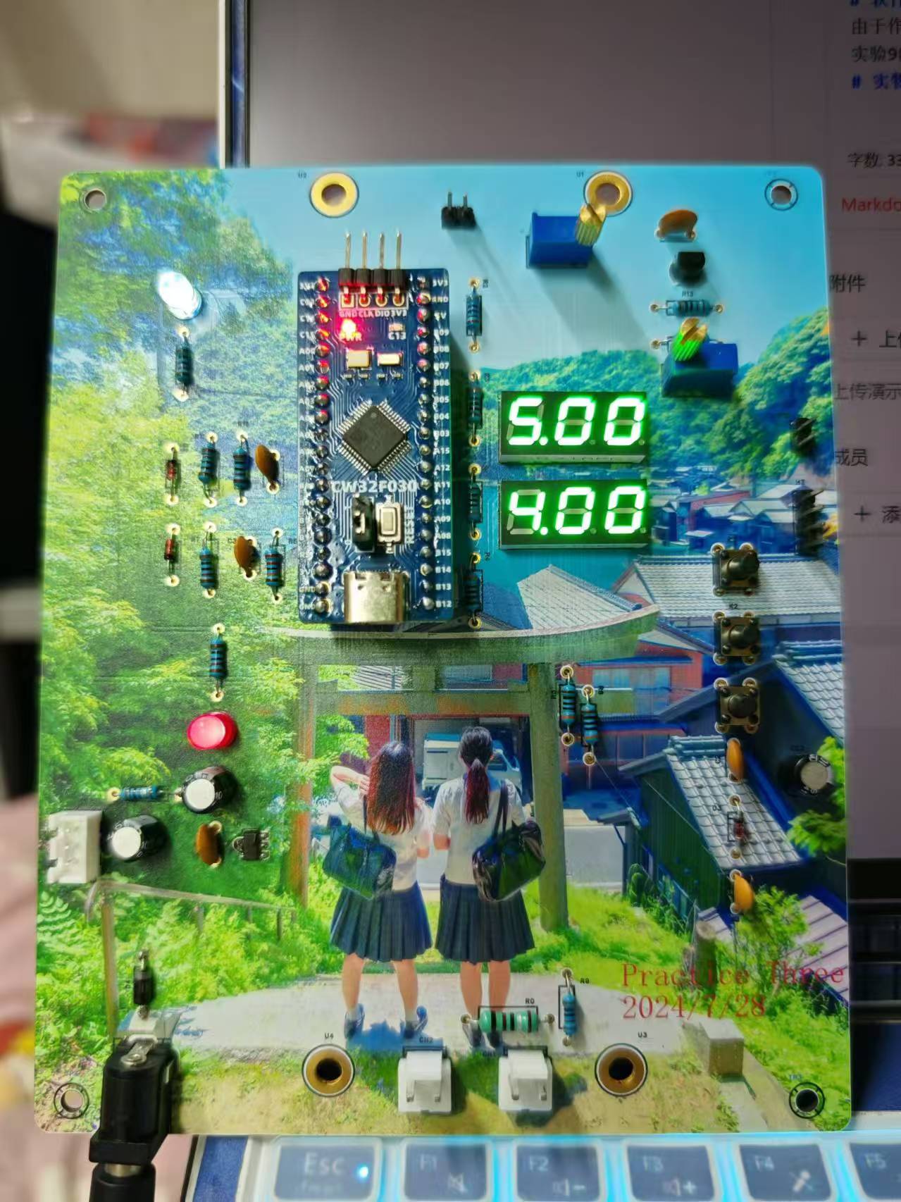
Based on the CW32F030 core board, the JLCPCB voltage and current meter training camp project was completed:
it supports the detection of voltage input from 0 to 30V (display accuracy of 0.01V) and current input from 0 to 3A (accuracy of 0.01A), and supports simultaneous display of voltage and current.
Hardware Development
: Power Supply Circuit:

A relatively stable 5V voltage is provided to the circuit using an SE8552K2-HF, and a series diode is used for reverse
polarity protection. Voltage Sampling Circuit:
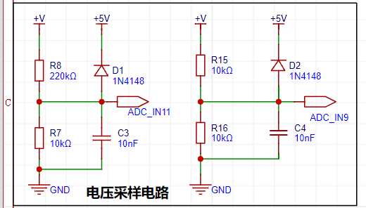
The reference voltage used is 1.5V, and the voltage range of this project is calculated to be 0-30V and 0-5V. Data is read through an ADC, and the voltage of the voltage divider resistor is calculated by comparing it with the reference voltage. The voltage measurement is calculated based on the resistance relationship between the two resistors.
Current Sampling Circuit

: Similar to voltage sampling, the voltage is sampled using an ADC, and the obtained value is compared with the 1.5V reference voltage to obtain the voltage of R0, thereby calculating the current in the circuit. Voltage
and Current Calibration Circuit
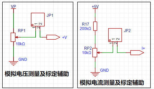
: The voltage and current meters are calibrated by rotating potentiometers JP1 or JP2 to change their resistance values, thereby changing the input voltage or current. An external multimeter can then be connected to calibrate the sampling circuit.
Software Development
: Since the author is not familiar with Keil software development, the software development of this project mainly refers to the example program of Experiment 9 in the training camp, and only the error messages have been modified. The project code can be found in the attached
physical diagram.
Experiment 9: Digital Voltmeter and Ammeter with Calibration Function.rar
Actual product image.zip
PDF_Voltage and Current Meters.zip
Altium_voltmeter_currentmeter.zip
PADS_Voltage and Current Meter.zip
BOM_Voltage and Current Meter.xlsx
92305
electronic

 2. Charging Boost Circuit:
  This uses a TP5400 charging boost chip to achieve battery charging boost functionality. Using an integrated chip reduces wiring complexity.
 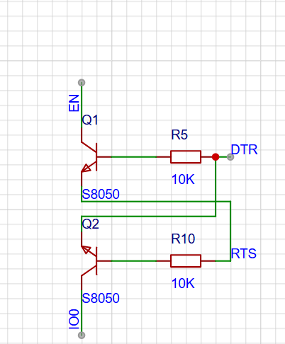 This circuit connects the CH340 and ESP32 to achieve serial port program download functionality.


 京公网安备 11010802033920号

 SG79XXT


