M0G3507 Battery Management
Hardware Configuration:
MSPM0G3507 chip (48-pin)
, ETA9740 battery management chip
, SSD1315 driver for OLED screen (based on IIC communication protocol)
, CH340 serial communication chip (can communicate with computer using Type-C data cable),
LDO linear regulator (3.3V). The board features an
external crystal oscillator (40MHz and 32768Hz)
, two programmable buttons with hardware debouncing, a reset button,
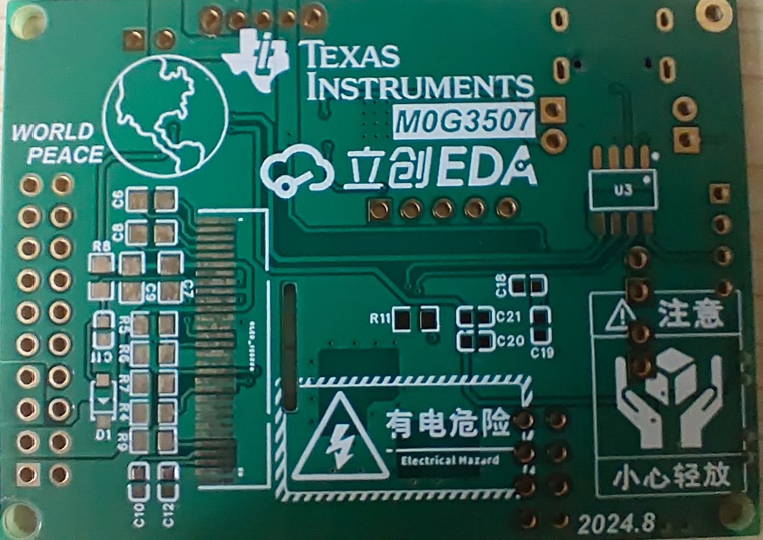
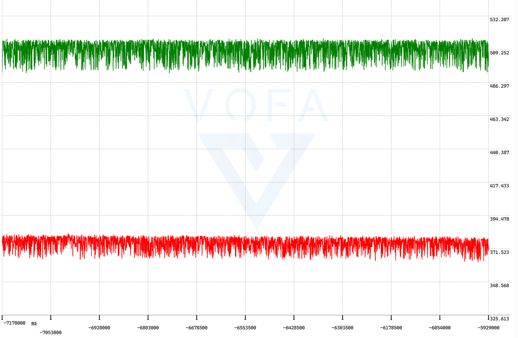
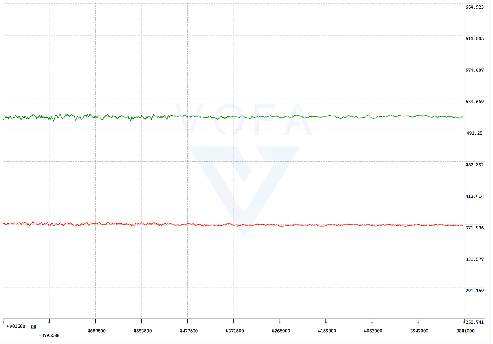
and 33+2 I/O ports . It is suitable for 1S lithium polymer batteries, outputting 5V and 3.3V voltages. It uses a Type-C charging interface and supports simultaneous charging and use. It can be programmed and used as a development board in addition to its battery management function . Disadvantages include limited functionality, displaying only battery voltage and one output voltage, and lacking a current detection circuit. The battery charging current is as high as 2A, and due to limited data on the battery management chip, modifications are not possible. The physical diagram shows the front and back of the board during charging . Regarding voltage acquisition: a resistor divider method is used to acquire the voltage, which is then converted to voltage via an ADC . Due to various reasons, the voltage reading fluctuates significantly, so a simple filtering algorithm is added to the software processing. The overall idea is to average twenty data points. To reduce error, these twenty data points are dynamically changing (similar to a queue in C language; a queue with a capacity of 20 is maintained at 20 whenever new data enters). Introducing a filtering algorithm can significantly reduce reading fluctuations. See the following diagram for specific effects: This is the waveform of directly averaging 20 data points. Because the sampling time of the microcontroller's ADC is on the order of microseconds, short-term readings will not show significant changes. Therefore, displaying the voltage waveform after every 20 readings cannot eliminate jitter. This is filtering with a sample size of 10. The 10 sampled data points are stored in an array. After each sample, the array (more precisely, the sum of the array values) is dynamically reset before voltage conversion. A significant improvement in waveform is evident. This is the sample size... A filter with a sample size of 20 still shows a significant reduction in jitter compared to a filter with a sample size of 10. Waveform display utilizes VOFA+ and the onboard serial port, allowing for easy waveform reading with a single data cable connection to the computer. To prevent inaccurate data due to battery power supply via Type-C, the jumper cap on the board can be removed, ensuring the computer shares ground with the development board instead of providing power. If you have better solutions or designs, please contact the author: qq3265809330. Software resources are available in the attachment (based on the CCS development environment).


 京公网安备 11010802033920号

 121-100-2-1-09BKSE


