Keil5 configuration

September 9, 2024
11:02

lcd driver (requires external import of related library files)


Put these three files into the group file of the created project (modular call is equivalent to)


LCD_Init(); // Initialize lcd
LCD_Clear(Black);// Clear screen and display initial background color
LCD_SetBackColor(Black); // Background color
LCD_SetTextColor(White); // Font color
char miao[10];
int hh = 0;
sprintf(miao," %d",hh); // Conversion function needs to include stdio.h header file
// Print the required content into the string
// I understand it as storing the hh integer data into the miao[] array, and then using the function pointer below to get the first address and input it to the next LCD_DisplayStringLine(Line1, (u8 *)miao);
// lcd screen character output function, line + content
CubeMx configuration
September 9, 2024 10:56
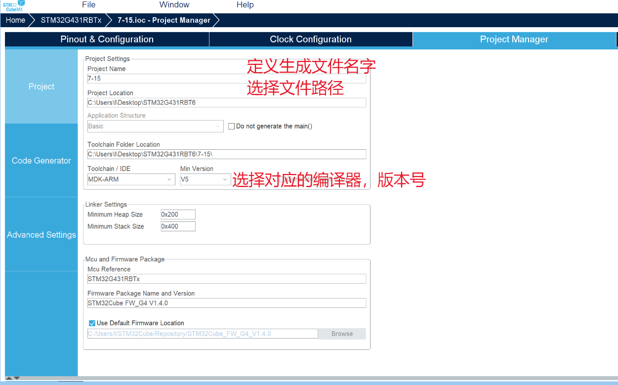
Create
a new project:
1. Chip selection (correct chip model, correct package)

2. Debug selection

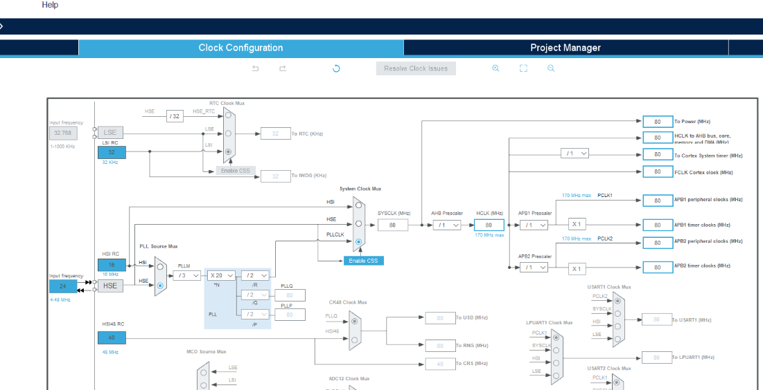
3. Clock configuration: first enable the clock as needed, then configure the clock tree.
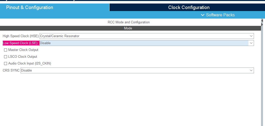
The clock tree configuration should be adjusted according to the actual external crystal oscillator on the board.
4. GPIO configuration

tips.
(September 9, 2024,
11:01 AM)
When using Keil 5, Ctrl + Alt + Space to display the prompt requires keyboard mode.
Redefining variable types.
(September 9, 2024,
10:50 AM
) `typedef signed char int8_t; // Alias for signed char, named int8_t `
typedef signed short int int16_t; // Alias for signed short integer short int, named int16_t `
typedef signed int int32_t; // Alias for signed integer short int, named int32_t `
typedef signed __INT64 int64_t; typedef unsigned char uint8_t; // Alias for unsigned char, named uint8_t `
typedef unsigned short int...` uint16_t; // Aliasing an unsigned short integer type uint16_t
typedef unsigned int uint32_t; // Aliasing an unsigned short integer type uint32_t
typedef unsigned __INT64 uint64_t;
/* 7.18.1.2 */ // Same as above, use other aliases
/* smallest type of at least n bits */
/* minimum-width signed integer types */
typedef signed char int_least8_t;
typedef signed short int int_least16_t; typedef signed
int int_least32_t;
typedef signed __INT64 int_least64_t;
/* minimum-width unsigned integer types */
typedef unsigned char uint_least8_t;
typedef unsigned short int uint_least16_t;
typedef unsigned int uint_least32_t;
typedef unsigned __INT64 uint_least64_t;
/* fastest minimum-width signed integer types */
typedef signed int int_fast8_t;
typedef signed int int_fast16_t; typedef signed
int int_fast32_t;
typedef signed __INT64 int_fast64_t;
/* fastest minimum-width unsigned integer types */
typedef unsigned int uint_fast8_t;
typedef unsigned int uint_fast16_t;
typedef unsigned int uint_fast32_t;
typedef unsigned __INT64 uint_fast64_t;
Timer interrupt
September 9, 2024,
11:03 AM

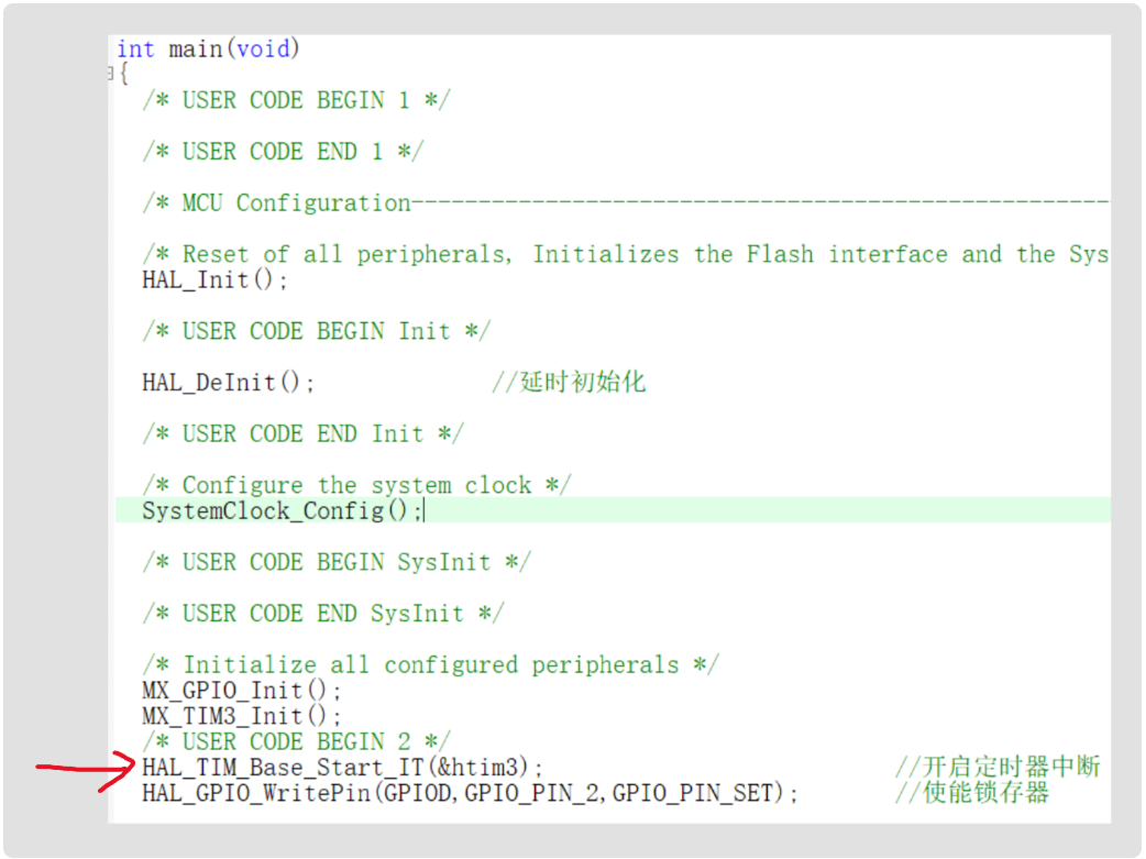
HAL_TIM_Base_Start_IT(TIM_HandleTypeDef *htim); // Enable clock interrupt, a necessary function, but note that it should be placed after the timer initialization function.
Interrupts can be configured in two ways:
void HAL_TIM_PeriodElapsedCallback(TIM_HandleTypeDef *htim)
{
if (htim->Instance == TIM1) // Ensure that the callback was triggered by timer TIM1
{
// Add your code here, such as updating variables, triggering an interrupt, etc.
}
}
void TIM3_IRQHandler(void)
{
HAL_TIM_IRQHandler(&htim3)
// Interrupt handler function
}

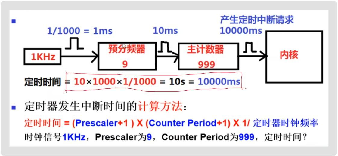
Timer timing calculation:
After enabling timer interrupts, the timer will enter the interrupt service function once after each count.
Interrupts:
preemption priority, response priority;
when multiple interrupt requests are made, they are handled according to the order of preemption and response. (Lower priority interrupts can be interrupted by higher priority interrupts) When
preemption and response priorities are the same, the system handles them according to the natural order.
(Therefore, interrupts must have a sequential order)
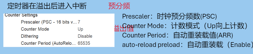
Understanding timers:
Timers are independent counters, unaffected by interrupts. Even when an interrupt is entered, the timer will continue counting.
Therefore, timers are used to replace delays. The interrupt handler function is entered only once after each count is completed. At this time, the program enters the interrupt service function, but this time is extremely short (I think it can be ignored). Compared to delays where the program stops, a better delay solution can be obtained.
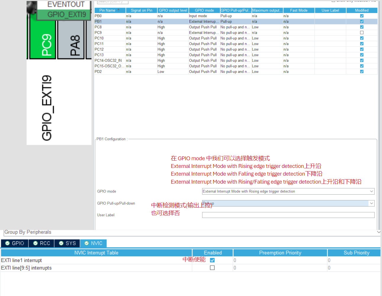
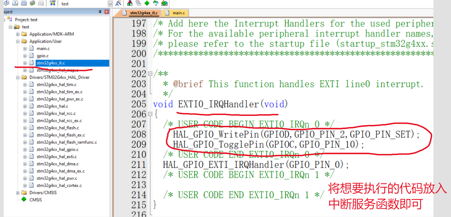
External Interrupts (Taking button interrupts as an example)
September 9, 2024,
11:09 AM
void EXTI1_IRQHandler(void) { HAL_GPIO_EXTI_IRQHandler(GPIO_PIN_1);
// External interrupt handling function }
void HAL_GPIO_EXTI_Callback(uint16_t GPIO_Pin)
{
// In hal_gpio.c, this is the callback function for external interrupts and must be placed under the main function
}
void HAL_GPIO_EXTI_Callback(uint16_t GPIO_Pin)
{
if(GPIO_Pin == GPIO_PIN_12)
{
}
} // Multi-button interrupt callback handling function
SPI Communication
September 9, 2024,
10:54


AM SPI is an abbreviation for Serial Peripheral interface. As the name suggests, it is a serial peripheral interface. It was first defined by Motorola on its MC68HCXX series processors.
SPI is a high-speed, full-duplex, synchronous communication bus that uses only four pins on a chip, saving pins and PCB layout space. It is primarily used in EEPROM, FLASH, real-time clocks, AD converters, and between digital signal processors and digital signal decoders.
SPI Master-Slave Mode
: SPI has two modes: master and slave. An SPI communication system requires one (and only one) master device and one or more slave devices. The device providing the clock is the master, and the device receiving the clock is the slave. Read and write operations on the SPI interface are initiated by the master device. When multiple slave devices exist, they are managed through their respective chip select signals.
SPI is full-duplex and has no defined speed limit; typical implementations can reach or even exceed 10 Mbps.
SPI Signal Lines
: The SPI interface generally uses four signal lines for communication:
SDI (data input), SDO (data output), SCK (clock), and CS (chip select).
MISO: Master input/slave output pin. This pin sends data in slave mode and receives data in master mode. MOSI: Master Output/Slave Input pin. This pin sends data in master mode and receives data in slave mode. SCLK: Serial Clock signal, generated by the master device. CS/SS: Slave Chip Select signal, controlled by the master device. Its function is to act as a "chip select pin," selecting a specific slave device, allowing the master device to communicate independently with a specific slave device, avoiding data line conflicts.
SPI Communication (
September 9, 2024
, 10:54 AM
) SPI is an abbreviation for Serial Peripheral Interface. It was first defined by Motorola on its MC68HCXX series processors.
SPI is a high-speed, full-duplex, synchronous communication bus that occupies only four pins on the chip, saving chip pins and PCB layout space. It is mainly used in EEPROM, FLASH, real-time clock, AD converters, and between digital signal processors and digital signal decoders.
SPI Master-Slave Mode
: SPI has two modes: master and slave. An SPI communication system requires one (and only one) master device and one or more slave devices. The device providing the clock is the master, and the device receiving the clock is the slave. Read and write operations on the SPI interface are initiated by the master device. When multiple slave devices exist, they are managed through their respective chip select signals.
SPI is full-duplex and has no defined speed limit; typical implementations can reach or even exceed 10 Mbps.
SPI Signal Lines
: The SPI interface generally uses four signal lines for communication:
SDI (Data Input), SDO (Data Output), SCK (Clock), and CS (Chip Select).
MISO: Master Input/Slave Output pin. This pin sends data in slave mode and receives data in master mode. MOSI: Master Output/Slave Input pin. This pin sends data in master mode and receives data in slave mode. SCLK: Serial clock signal, generated by the master device. CS/SS: Slave chip select signal, controlled by the master device. Its function is to act as a "chip select pin," that is, to select a specific slave device, allowing the master device to communicate independently with a specific slave device, avoiding data line conflicts.
Serial communication (
September 9, 2024
, 11:15 AM):
I2C is half-duplex, SPI is full-duplex, and UART is full-duplex.
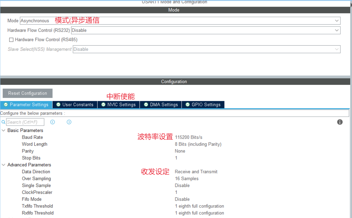
USART: Universal Synchronous and Asynchronous Receiver/Transmitter
; UART: Universal Asynchronous Receiver/Transmitter.
When performing asynchronous communication, there is no difference between the two. The difference is that USART has synchronous communication capabilities, which UART lacks. This synchronous communication capability allows USART to be used like SPI, for example, to drive an SPI device.
Blocking transmission: The microcontroller waits for the transmission to complete and does nothing else during the process.
Non-blocking transmission: Transmission interrupt is enabled, and a callback function is executed upon completion.
HAL_StatusTypeDef HAL_UART_Transmit(UART_HandleTypeDef *huart, uint8_t*pData, uint16_t Size, uint32_t Timeout); // Blocking transmission
HAL_StatusTypeDef HAL_UART_Transmit_IT(UART_HandleTypeDef *huart, uint8_t*pData, uint16_t Size); // Non-blocking transmission
void HAL_UART_TxCpltCallback(UART_HandleTypeDef *huart); // Callback function
void HAL_UART_TxHalfCpltCallback(UART_HandleTypeDef *huart); // Half-callback function
HAL_StatusTypeDef HAL_UART_Receive(UART_HandleTypeDef *huart, uint8_t*pData, uint16_t Size, uint32_t Timeout) `neout);` // Blocking receive `HAL_StatusTypeDef HAL_UART_Receive_IT(UART_HandleTypeDef *huart, uint8_t *pData, uint16_t Size);` // Non-blocking receive `void HAL_UART_RxCpltCallback(UART_HandleTypeDef *huart);` `void HAL_UART_RxHalfCpltCallback(UART_HandleTypeDef *huart);`

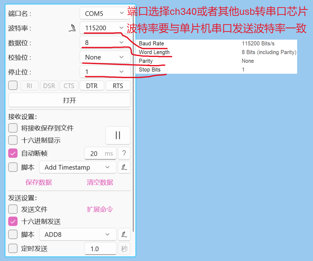
When performing serial port transmission and reception, you must know the corresponding pin number of the serial port.
The ch340 RX is connected to the microcontroller TX
, and the TX is connected to the microcontroller RX. They must share a common ground! (
Serial port debugging tool
standard library
) void Uart1_init(u32 bound){
//GPIO port settings
GPIO_InitTypeDef GPIO_InitStructure;
USART_InitTypeDef USART_InitStructure;
RCC_APB2PeriphClockCmd(RCC_APB2Periph_USART1|RCC_APB2Periph_GPIOA, ENABLE); //Enable USART1, GPIOA clock
//USART1_TX GPIOA.9
GPIO_InitStructure.GPIO_Pin = GPIO_Pin_9; //PA.9
GPIO_InitStructure.GPIO_Speed = GPIO_Speed_50MHz;
GPIO_InitStructure.GPIO_Mode = GPIO_Mode_AF_PP; // Multiplexed push-pull output
GPIO_Init(GPIOA, &GPIO_InitStructure); // Initialize GPIOA.9
// USART1_RX GPIOA.10 initialization
GPIO_InitStructure.GPIO_Pin = GPIO_Pin_10; // PA10
GPIO_InitStructure.GPIO_Mode = GPIO_Mode_IN_FLOATING; // Floating input
GPIO_Init(GPIOA, &GPIO_InitStructure); // Initialize GPIOA.10
// USART initialization settings
USART_InitStructure.USART_BaudRate = bound; // Serial port baud rate
USART_InitStructure.USART_WordLength = USART_WordLength_8b; // Word length is 8 bits data format
USART_InitStructure.USART_StopBits = USART_StopBits_1; // One stop bit
USART_InitStructure.USART_Parity = USART_Parity_No; // No parity bit
USART_InitStructure.USART_HardwareFlowControl = USART_HardwareFlowControl_None; // No hardware flow control USART_InitStructure.USART_Mode = USART_Mode_Rx | USART_Mode_Tx; // Transmit/receive mode
USART_Init(USART1, &USART_InitStructure); // Initialize serial port 1
//USART_ITConfig(USART1, USART_IT_RXNE, ENABLE); // Enable serial port receive interrupt
USART_Cmd(USART1, ENABLE); // Enable serial port 1
}
Encoder driver
September 9, 2024
11:21
void HAL_GPIO_EXTI_Callback(uint16_t GPIO_Pin) //PB12, PB13 encoder counting function
{
if(GPIO_Pin == GPIO_PIN_12)
{
if(HAL_GPIO_ReadPin(GPIOB, GPIO_PIN_13) == HAL_GPIO_ReadPin(GPIOB, GPIO_PIN_12))
{
key_count--;
} else
{
key_count++;
}
}
}
Used in conjunction with the following code:
if(key_count!=0)
{
key_num += key_count;
key_count = 0;
}
Note that the rotation direction is determined by interrupt handling.
void EXTI0_IRQHandler(void) // Forward rotation: The rising edge of A corresponds to the low level of B; Reverse rotation: The rising edge of B corresponds to the low level of A.
{
if (EXTI_GetITStatus(EXTI_Line0) == SET) // Check if encoder A is high and if an interrupt has been triggered
{
if (GPIO_ReadInputDataBit(GPIOB, GPIO_Pin_1) == 0) // Check if encoder B is low
{
Encoder_Count++;
}
EXTI_ClearITPendingBit(EXTI_Line0); // If yes, clear the flag
}
}
void EXTI1_IRQHandler(void)
{
if (EXTI_GetITStatus(EXTI_Line1) == SET) // Check if encoder B is high and if an interrupt has been triggered
{
if (GPIO_ReadInputDataBit(GPIOB, GPIO_Pin_0) == 0) // Check if encoder A is low
{
Encoder_Count--;
}
EXTI_ClearITPendingBit(EXTI_Line1); // If yes, clear the flag
}
Define
two interrupt functions, EXTI0_IRQHandler and EXTI1_IRQHandler. The basic logic is the same as described in the first section: first, check if the first interrupt has been triggered, i.e., whether pin A is on a rising edge. Pin A is connected to GPIOB_0, corresponding to interrupt 0. Then, check if pin B is low.
EXTI_InitTypeDef EXTI_InitStructure; EXTI_InitStructure.EXTI_Line=EXTI_Line0 | EXTI_Line1; // Configure interrupt line EXTI_InitStructure.EXTI_LineCmd=ENABLE; // Enable or disable interrupt EXTI_InitStructure.EXTI_Mode=EXTI_Mode_Interrupt; // Define interrupt mode EXTI_InitStructure.EXTI_Trigger=EXTI_Trigger_Rising; // Trigger interrupt method, select rising edge trigger EXTI_Init(&EXTI_InitStructure);
Clearly distinguish the priority of the two interrupts, judge one before the other.
OLED driver notes (
September 9, 2024,
11:26 AM ):
First, import the relevant font library .h files. The
OLED .c and .h files are included in the compiler . The
main function includes the header file.
Configure the hardware I/O; you only need to enable the two communication interfaces.
Note the clock frequency; too high a clock frequency may affect the display effect.
(Hardware IIC is implemented through the IIC controller hardware module to achieve IIC communication, while software IIC is simulated by software control of GPIO ports)
OLED_Init();//oled initialization file
char text[20];
sprintf(text, character (%d), variable);
OLED_ShowString(2,1,text);
Clear screen problem, set screen background color, etc.
PWM configuration
September 9, 2024
11:27
Just configure the corresponding timer PWM output channel in CubeMx


HAL_TIM_PWM_Start(&htim2,TIM_CHANNEL_1);
TIM2->CCR1 = (constant/timer count value or timer overflow value)//Control tim2 channel 1 output PWM duty cycle
PWM effective drive two codes
PWM frequency: Freq = CK_PSC/(PSC+1)/(ARR+1)
PWM duty cycle: Duty = CCR/(ARR+1)
PWM resolution: Reso = 1/(ARR+1)
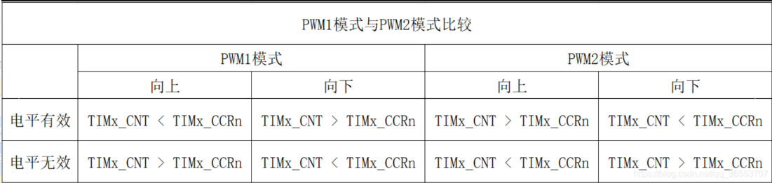
Comparison of PWM1 and PWM2 Modes of
STM32 Timer The STM32 timer has two PWM modes: PWM1 and PWM2. These two modes are similar yet opposite.
PWM1 Mode: Counting up, when TIMx_CNT = TIMx_CCRn, channel n of timer TIMx is invalid; otherwise, it is valid.
PWM2 Mode: Counting up, when TIMx_CNT = TIMx_CCRn, channel n of timer TIMx is valid; otherwise, it is invalid.
Below is a comparison table of PWM1 and PWM2 modes, which clearly shows the differences between the two.
Comparison of two PWM modes: Note:
Throughout the text, TIMx refers to the STM32 timer, where x represents a specific timer, and the value needs to be determined based on the chip;
TIMx_CNT refers to the counter register value of timer TIMx;
TIMx_CCRn refers to the capture/compare register value, where n represents a specific channel, with values of 1, 2, 3, and 4;
ADC sampling:
September 9, 2024,
11:29 AM

. Simply start the relevant pin ADC sampling channel in CubeMx.


 京公网安备 11010802033920号

 0805J0100821GXT


