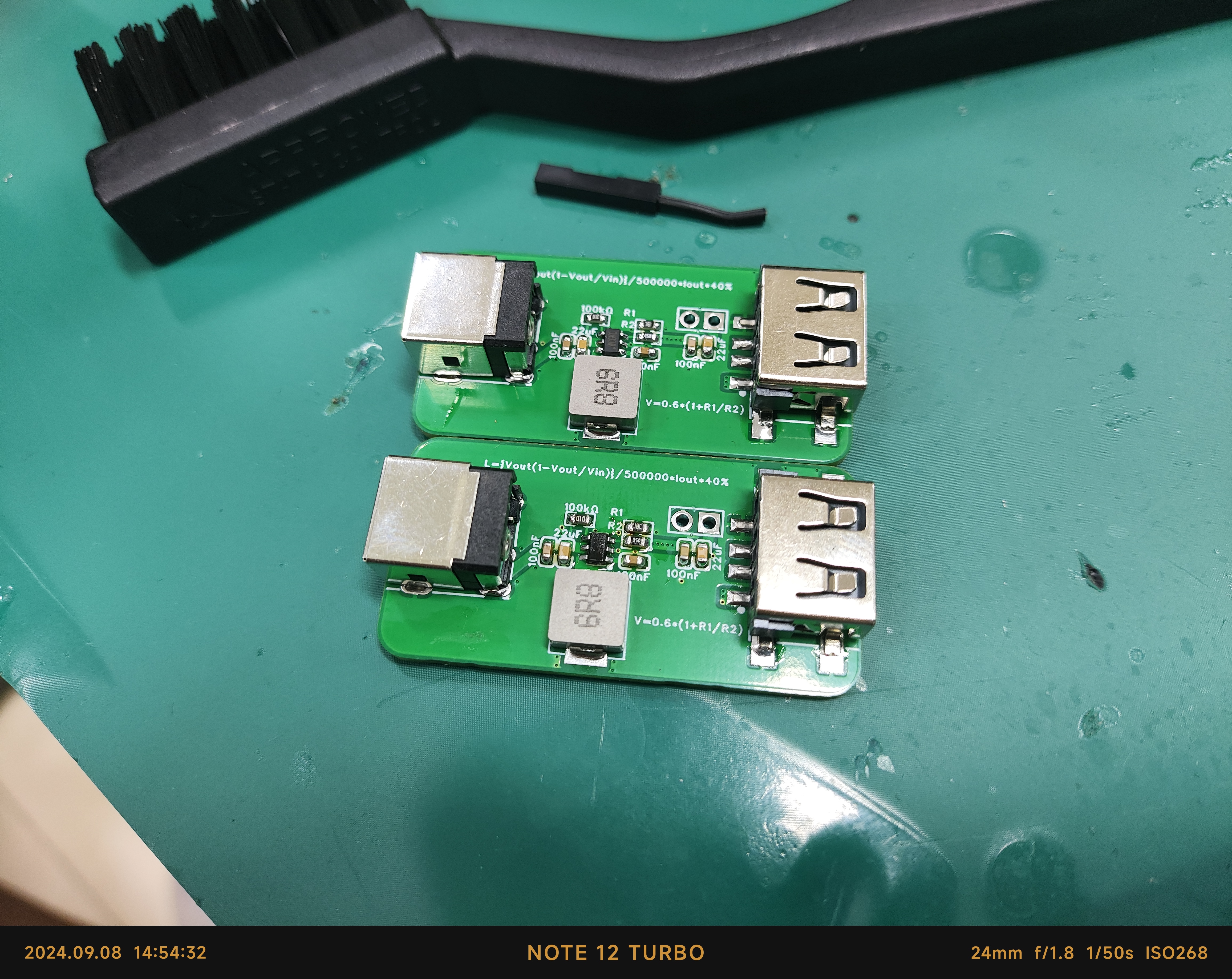
This is a functional verification board for the SY8113BADC, used to verify the functions of the SY8113BADC. It features
DC 5525 input, USB output, and reserved pin header outputs; the default configuration is 12V to 5V, with a maximum current of 2A . [Images:
An IoT clock and a temperature and humidity meter based on the ESP32-WROOM-32 (main controller ESP32-D0WDQ6) module are designed to collect data from weather stations.
The nanopc-t4 development board is compatible with the cat screen adapter board, using the mainline Linux 6.6 kernel, and perfectly supports display and touch.
The nanopc-t4 MIPI adapter board is compatible with the Taishanpai cat screen
using a Linux 6.6 mainline with the Armbian Rockchip64_6.6 patch, perfectly supporting display and touch.

1. Usage Method
: 1.1 Place the patch in the Armbian build directory and compile the image directly.
Place the user patch from the attachment into the userpatches/kernel/archive/rockchip64-6.6 directory of the Armbian build directory. Use `./compile.sh EXPERT="yes" KERNEL_GIT=shallow` to compile. Select the current kernel. Before compiling, it's best to manually select DRM_PANEL_SIMPLE as Y in the kernel configuration and compile it into the kernel so the screen can light up earlier during kernel startup. After compilation, burn the image, connect the screen, and the screen should light up upon startup.
1.2 The development board originally ran an Armbian system.
A DTS overlay can be used. For DTS overlay information, refer to my kernel repository https://github.com/JackHuang021/kernel-nanopct4. Manually convert `arch/arm64/boot/dts/rockchip/rk3399-nanopc-t4-dsi.dtsi` to DTS overlay format. If the development board originally ran an Armbian system, directly use `armbian-add-overlay`. If it prompts that DTS overlay is not supported, refer to this repository https://github.com/EricaLinaG/armbian-boot-edp-overlay to modify the Armbian boot file to boot.scr.
1.3 Modify the FriendlyARM official 6.1 kernel.
For using the FriendlyARM official 6.1 kernel, refer to my kernel repository https://github.com/JackHuang021/kernel-nanopct4. Regarding MIPI DSI submissions, simply merge the relevant patches and compile
. Regarding the cat screen
, the seller's information states the touch chip is GT970, but Goodix doesn't actually produce that model. The silkscreen markings on the touch chip indicate it's actually GT9157. The GT9157 mainline kernel's goodix.c directly supports
3. The attached file contains userpatch documentation
needed to compile the cat screen for Armbian.
Use an ESP32C3 to connect to WiFi, obtain the weather and time, and use an AHT20 to obtain local temperature and humidity for display.
This product emphasizes simplicity and crudeness; it just needs to work. Its performance is not high, its power consumption is not small, its cost is not low, and its appearance is also unattractive.
The design goal
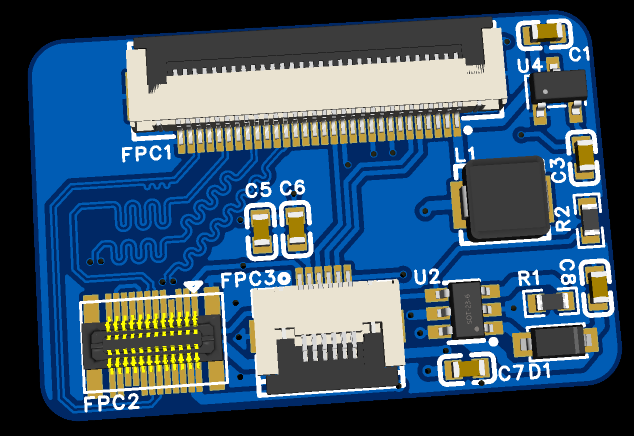
is to create a sound card primarily for microphone recording. Requirements include a small size, XLR input, and 48V phantom power.
The chosen
USB audio chip is the TI PCM2912A, released over a decade ago. While its performance is outdated and it's not cheap, it requires no firmware flashing, is ready to use immediately, and has detailed and easy-to-understand official documentation, making it suitable for beginners like myself. The XLR interface requires a differential-to-single-ended converter to input the PCM2912A, so the ADI SSM2019 preamplifier chip was chosen. It has adjustable gain but requires both positive and negative power supplies. The power supply is the only original component. The phantom power supply requires a DC 48V supply. The conventional approach is to boost the voltage and then filter it, or boost it to around 20V and then double and rectify it. However, considering the complexity of the power supply design and the positive and negative voltage requirements of the preamplifier chip, I used two Mornsun B0524S-1WR3 5V to 24V power modules in series. After filtering, the output is 48V. Simultaneously, the zero potential of the SSM2019 is separated from the circuit's GND and connected to the midpoint of two series-connected 15V Zener diodes to obtain a ±15V power supply. Based on my personal experience
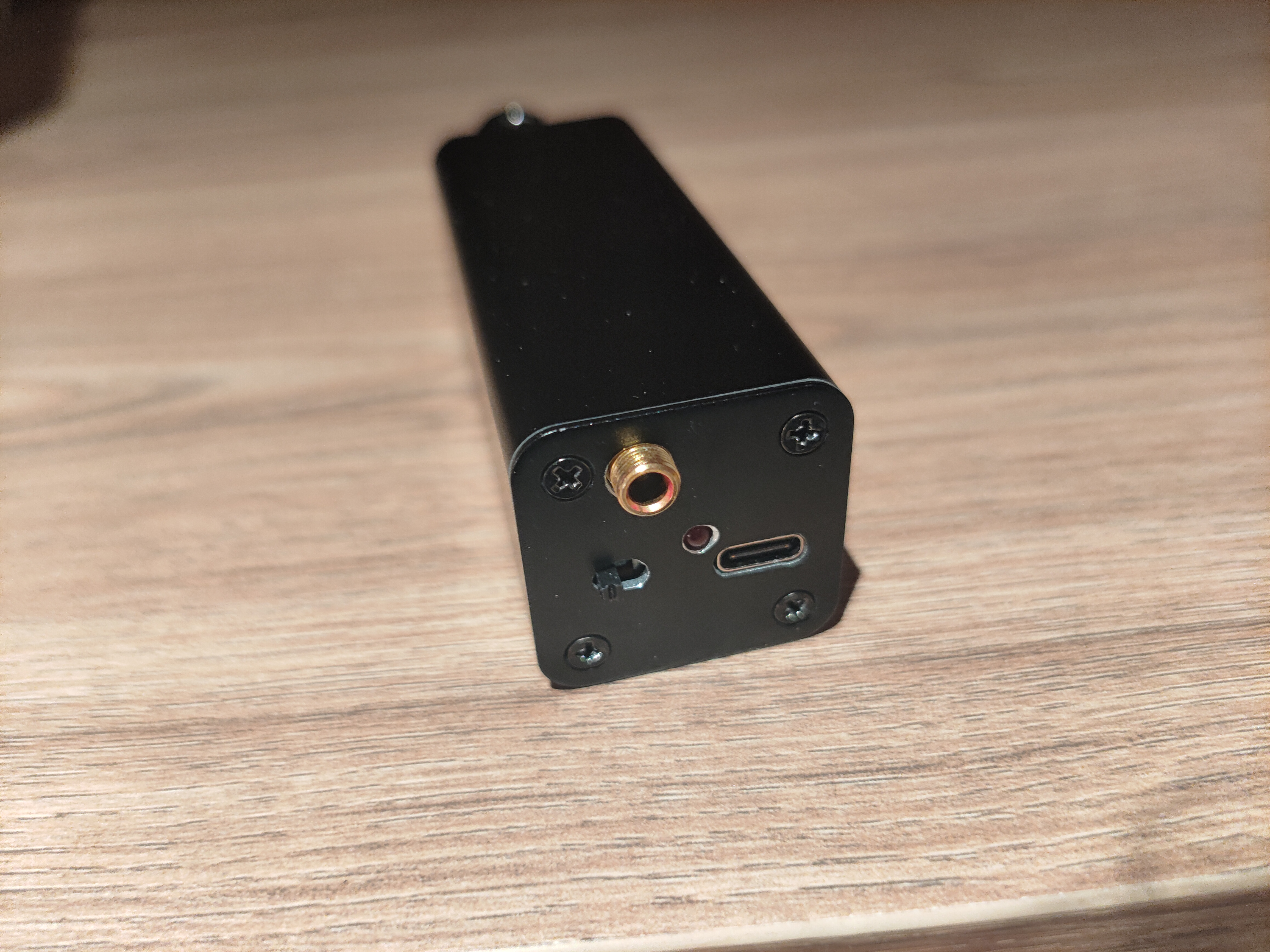
in structural design
, for microphone circuits, proper shielding can significantly reduce background noise. Therefore, a metal casing with good electrical contact between components and connection to GND on the circuit board is essential. Initially, I considered using a 26mm diameter cylindrical aluminum tube casing for an 18650 power bank kit, but with several large capacitors and power modules in the circuit, the internal space was too limited. Therefore, a 32mm square aluminum tube casing was used. The anodized layer on the aluminum casing end cap is sanded off, and the PCB is connected via enameled wire. Holes in the end cap are made using a bench drill and file; alternatively, you could try designing the PCB to make the end cap, remembering to add copper plating and solder mask openings. For the PCB GND, you could try directly soldering a window at the contact point with the aluminum casing slot.

The XLR connector is obtained by cutting off part of the plastic from an XLR male connector
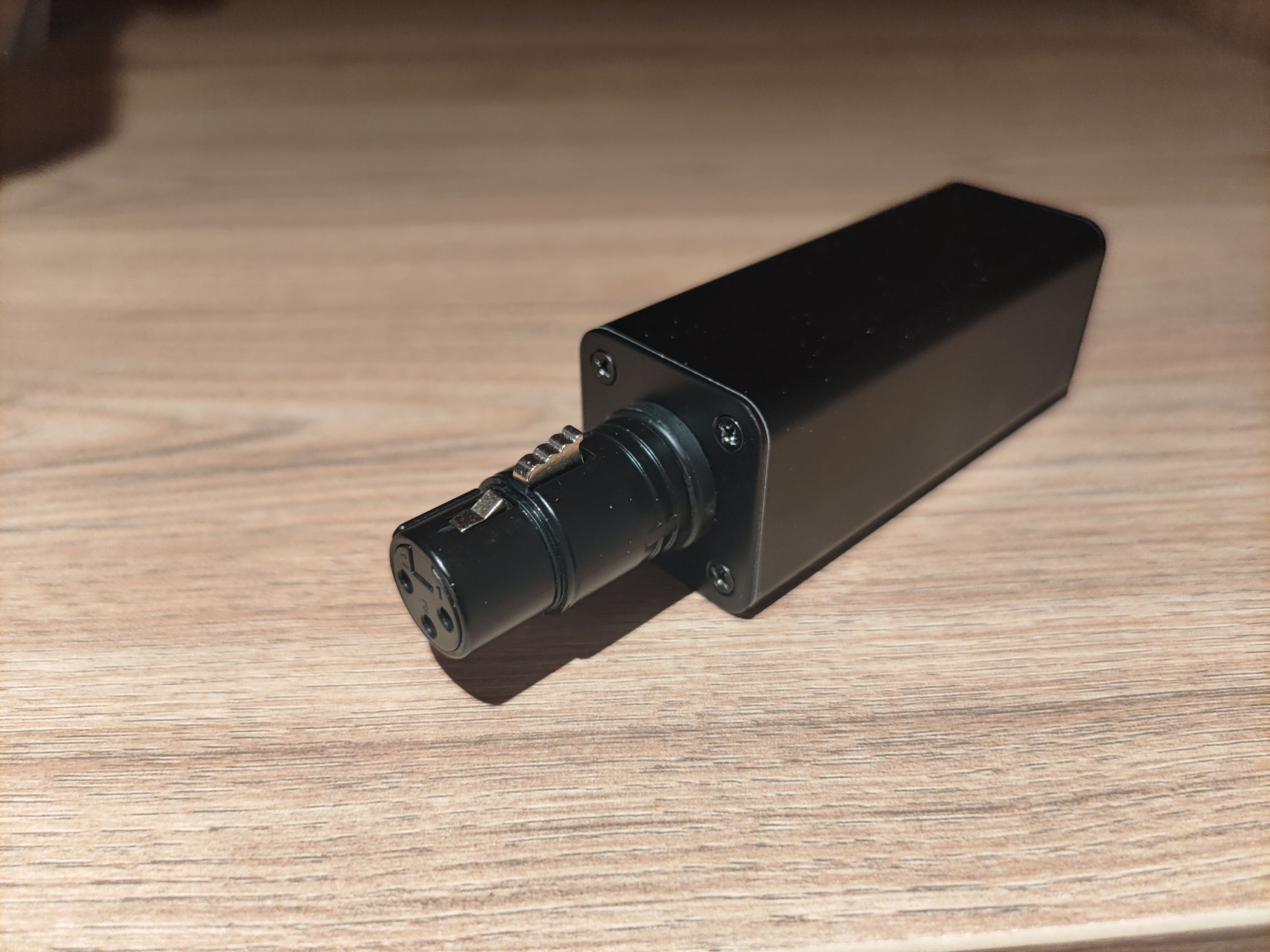
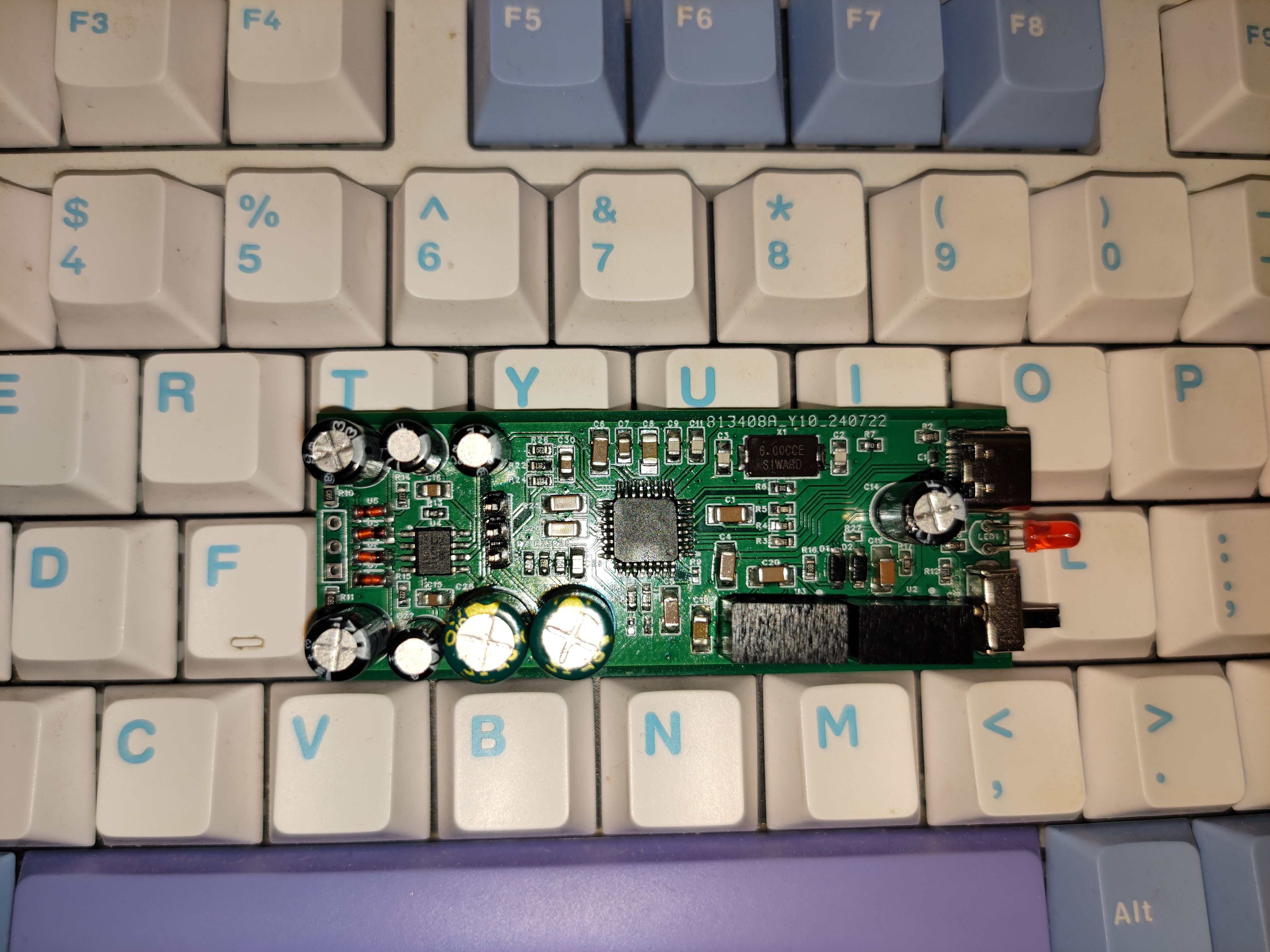
(I bought a refurbished chip; the silkscreen printing disappeared after wiping with alcohol...).
The circuit packaging is rather messy; 0603 resistors are used, along with 0805 and 1206 capacitors. The headphone section is drawn rather haphazardly; it can be modified if required.
Altium - Portable USB sound card with 48V phantom power and microphone preamp.zip
A small IoT project designed and implemented using the LCSC ESP32 development board.
I. Overview
I'm also a beginner, majoring in IoT engineering. While studying, I found it very interesting to do small IoT projects, but my skills are limited. Here, I'll showcase a small project I've created. Due to insufficient circuit design and soldering skills, after careful consideration, I decided to use the ESP32 core board from LCSC to simplify the design process and reduce the difficulty.
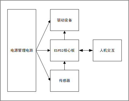
The system is divided into two parts: the ESP32 device acts as the lower-level machine, collecting data from sensors such as temperature, humidity, and illuminance; the WeChat mini-program acts as the upper-level machine, receiving status information reported by the device and remotely controlling the on/off status of the device hardware. The figure shows a simplified system structure diagram.

II. ESP32 Device Side The
ESP32 device side includes a power supply circuit, core board, sensors, driver devices, and a human-machine interface.
2.1 Power Management Circuit
The ESP32 core board has a USB interface, which can obtain 5V power through the USB-C interface. The power circuit on the core board converts the 5V to 3.3V to provide power to chips such as the MCU. Therefore, the device side also uses the USB 5V power input. However, due to the need to expand the equipment to include an OLED display, sensors, and other peripherals, to ensure power stability and sufficient power, an AMS1117-3.3 converter is used on the baseboard to transform the 5V to a separate 3.3V line to power the display, sensors, etc.

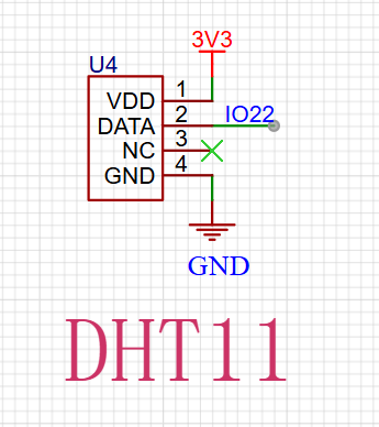
2.2 Sensors
Sensors include a DHT11 temperature and humidity sensor, a light intensity sensor, and an MQ series gas sensor. The DHT11 uses a single bus to communicate with the ESP32, the light intensity sensor uses a photoresistor voltage divider for data acquisition, and the MQ series sensors are powered by a 5V power supply for heating and are also connected to the ESP32's ADC acquisition pin using a voltage divider. These sensors collect environmental status information and pass it to the ESP32 for processing and calculation.
2.3 Driving Equipment
Driving equipment includes a fan and a water pump, simulating ventilation, cooling, and irrigation functions. Both are powered by a 5V power supply and controlled by a transistor driver circuit.

2.4 Human-Machine Interaction
A 0.96-inch OLED display provides visual operation, and three buttons are used to read user input to control system logic.
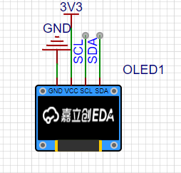
The 0.96-inch OLED communicates with the ESP32 via the I2C bus, making program porting and control relatively convenient, and the speed is sufficient to meet the requirements.
2.5 Device Networking:
The ESP32 connects to the network via Wi-Fi and accesses the MQTT server, publishing heartbeat data every second under a specified topic in JSON format. It also subscribes to topics that issue commands from the host computer and receives commands from the host computer.
The device-side code is written, compiled, and burned using the Arduino IDE. Arduino's rich library resources greatly reduce development difficulty and make development quick and convenient, but it is not conducive to learning the underlying layers. Further development will utilize ESP-IDF for device-side development.
III. WeChat Mini Program
: The mini program is developed natively using WeChat Developer Tools + JS + WXML + WSS, creating a simple interface that displays basic sensor data and on/off status. The mini program connects to the MQTT server through the mqtt.js library, subscribing to and publishing data to achieve communication with the device.

752f57f29d3c7cd409b491c90e154c8.jpg
WeChat image_20240908183155.jpg
9853be03b884678940f1758926eac637.mp4
esp32iotfarming.zip
PDF_ESP32 IoT Smart Agriculture System Based on LCSC Development Board.zip
Altium-based ESP32 IoT Smart Agriculture System (based on LCSC development board).zip
PADS_ESP32 IoT Smart Agriculture System Based on LCSC Development Board.zip
BOM_ESP32 IoT Smart Agriculture System Based on LCSC Development Board.xlsx
92423
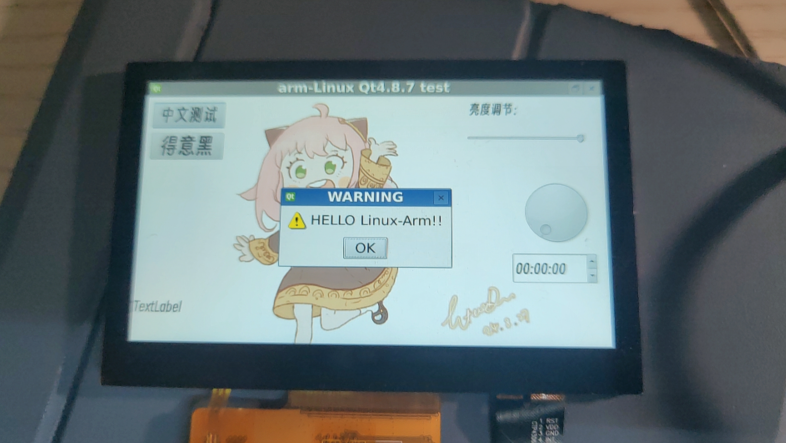
F1C200S Mini Linux Screen Development Board [Double-layer board + Qt4.8.7]
This is a small Linux development board based on the Allwinner F1C200S kernel, featuring a 4.3-inch 480*800 RGB666 screen. The system is already ported: uboot (Litchi Pi), kernel linux5.7.1, rootfs: Debian 11.
1. Project Introduction
This project designs and builds a low-cost Linux development board with a 4.3-inch 480*800 LCD based on the Allwinner F1C200S SOC, mainly for Qt4.8.7 or LVGL graphical interface development. The development board is equipped with 256Mbit SPI Flash, ESP8089 WIFI (SPI interface), RGB666 LCD, IIC touch interface, headphone jack, USB2.0 & UART (typec), etc., which can meet most of the needs of Linux development.
Reference project: https://oshwhub.com/fanhuacloud/f1c200s_lcd_backup
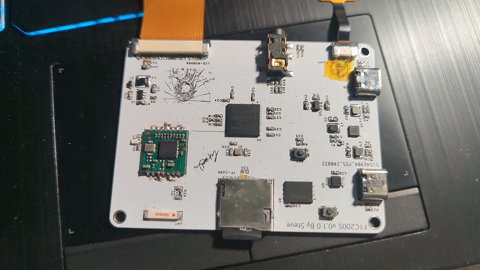
2. Hardware Design Summary
This SOC needs to provide 1.1V, 2.5V and 3.3V digital power supply and 2.8V analog power supply. The digital section uses an EA3036 three-channel DC-DC chip, the analog 2.8V is provided by an RT9193-28GB LDO (note the output voltage of this LDO when purchasing), and the LCD backlight constant current driver is implemented using an SGM3732.
All hardware has been verified to be usable! The actual PCB diagram is shown below:
The LCD screen used in this article is a 4.3-inch 800*480 GT911 touch chip LCD screen from "Yoyuan Hong Technology". If you do not want to modify the screen timings of the kernel and uboot, you can directly purchase the same model from Taobao.
3. Software Porting
Full text reference tutorial for software and driver porting: https://blog.csdn.net/qq_41709234/category_12158774.html
First, it is recommended to configure the system environment and compiler. I compiled U-Boot and the Kernel using Ubuntu 20.04 with the compiler arm-linux-gnueabi (gcc version 7.2.1 20171011). However, it's important to note that the F1C200S kernel is based on the ARMv5 architecture. Compiling either tslib or Qt requires an older compiler, while Qt5 and later versions require a higher gcc version. Therefore, the older compiler wouldn't work, and I had to port Qt 4.8.7. If I continued using the above compiler, the compiled software would display an "illegal instruction" error when run on the board. Later, during the porting process, I switched to Ubuntu 16 & arm-none-linux-gnueabi (gcc version 4.8.3 20140320), and the programs compiled with this version ran normally on the F1C200S. (U-Boot and kernel were compiled using a newer compiler; older ones were used instead of the newer ones.)
3.1 For pulling and compiling U-Boot,
refer to the Lichee Pi tutorial: https://wiki.sipeed.com/soft/Lichee/zh/Nano-Doc-Backup/get_started/first_eat.html
sudo apt-get install git
git clone https://gitee.com/LicheePiNano/u-boot.git
cd u-boot# View branches
git branch -a
# Switch to the Nano branch
git checkout nano-lcd800480# Here, make is informed to use all cross-compilation tools under arm-linux-gnueabi, the target architecture is Arm, and the default configurations are set to the nano spiflash support version
make ARCH=arm CROSS_COMPILE=arm-linux-gnueabi-f1c100s_nano_uboot_defconfig
Change the default serial port to serial port 1 under U-Boot:
1. /arch/arm/dts/suniv-f1c100s-lichepi-nano.dts:
aliases { //serial0 = &uart0; serial1 = &uart1; };
chosen { //stdout-path = "serial0:115200n8"; stdout-path = "serial1:115200n8"; };
&uart0 { //pinctrl-names = "default"; //pinctrl-0 = ; //status = "okay";};
&uart1 { pinctrl-names = "default"; pinctrl-0 = ; status = "okay";};
2. /arch/arm/dts/suniv.dtsi:
pio modification:
uart0_pins_a: uart-pins-pe {
//pins = "PE0", "PE1";
//function = "uart0";
};
uart1_pins_a: uart-pins-pa {
pins = "PA2", "PA3";
function = "uart1";
};
3. /arch/arm/include/asm/arch-sunxi/gpio.h:
#define SUNIV_GPE_UART0 5+#define SUNIV_GPA_UART1 5+#define SUNIV_GPE_UART2 3
4. /arch/arm/mach-sunxi/board.c:
@@ -87,6 +87,14 @@ static int gpio_init(void) sunxi_gpio_set_cfgpin(SUNXI_GPE(0), SUNIV_GPE_UART0); sunxi_gpio_set_cfgpin(SUNXI_GPE(1), SUNIV_GPE_UART0); sunxi_gpio_set_pull(SUNXI_GPE(1), SUNXI_GPIO_PULL_UP);+#elif CONFIG_CONS_INDEX == 2 && defined(CONFIG_MACH_SUNIV)+ sunxi_gpio_set_cfgpin(SUNXI_GPA(2), SUNIV_GPA_UART1);+ sunxi_gpio_set_cfgpin(SUNXI_GPA(3), SUNIV_GPA_UART1);+ sunxi_gpio_set_pull(SUNXI_GPA(3), SUNXI_GPIO_PULL_UP);+#elif CONFIG_CONS_INDEX == 3 && defined(CONFIG_MACH_SUNIV)+ sunxi_gpio_set_cfgpin(SUNXI_GPE(7), SUNIV_GPE_UART2);+ sunxi_gpio_set_cfgpin(SUNXI_GPE(8), SUNIV_GPE_UART2);+ sunxi_gpio_set_pull(SUNXI_GPA(8), SUNXI_GPIO_PULL_UP); #elif CONFIG_CONS_INDEX == 1 && (defined(CONFIG_MACH_SUN4I) || defined(CONFIG_MACH_SUN7I) || defined(CONFIG_MACH_SUN8I_R40))
5. `/include/configs/suniv.h
+#undef CONFIG_CONS_INDEX+#define CONFIG_CONS_INDEX 3`
*Finally, add the following to u-boot's bootargs: `setenv bootargs console=tty0 console=ttyS1,115200 panic=5 rootwait root=/dev/mmcblk0p2 earlyprintk rw`
*Note that you should add the following to bootcmd to boot the kernel: `load mmc 0:1 0x80008000 zImage;load mmc 0:1 0x80c08000 suniv-f1c100s-licheepi-nano.dtb;bootz 0x80008000 - 0x80c08000;
` *If you need to use an LCD under u-boot, please configure ARM architecture --> Enable graphical u-boot console on HDMI, LCD, or VGA to Y, and then configure the sibling LCD panel timing details. The timing parameters are: x:800, y:480, depth:18, pclkkhz:25000, le:8, ri:8, up:16, lo:16, hs:4, vs:4, sync:3, vmode:0 (Please modify the timing parameters according to your own LCD).
3.2 Kernel porting and driver porting compilation
complete reference tutorial: https://blog.csdn.net/qq_41709234/category_12158774.html (See sections 3-10). However, some peripheral addresses in the device tree need to be modified according to the corresponding hardware by referring to the F1C100S datasheet (such as the SPI interface for Wi-Fi).
The GT1151 touch chip driver in this tutorial is fully compatible with GT911 without any modifications.
*Regarding modifications to the kernel audio section, refer to: https://linux-sunxi.narkive.com/3zRXUcrE/rfc-patch-00-10-add-support-for-dma-and-audio-codec-of-f1c100s
3.3 Regarding tslib 1.21 and qt 4.8.7
, refer to: https://whycan.com/p_58590.html
and https://www.cnblogs.com/guanglun/p/9277667.html
qt 4.8.7 compilation options: ./configure -prefix /home/steve/arm/arm-qt -opensource -embedded arm -confirm-license -qt-sql-sqlite -qt-gfx-linuxfb -plugin-sql-sqlit -no-qt3support -no-phonon -no-svg -no-webkit -no-javascript-jit -no-script -no-scripttools -no-declarative -no-declarative-debug -qt-zlib -no-gif -qt-libtiff -qt-libpng -no-libmng -qt-libjpeg -no-rpath -no-pch -no-3dnow -no-avx -no-neon -no-openssl -no-nis -no-cups -no-dbus -embedded arm -platform linux-g++ -little-endian -qt-freetype -no-opengl -no-glib -qt-mouse-tslib -I/home/steve/arm/arm-tslib/include -L/home/steve/arm/arm-tslib/lib -no-neon
Environment variables added:
export PATH=/bin:/sbin:/usr/bin/:/usr/sbin:/opt/tslib/binexport TSLIB_ROOT=/usr/lib/arm-tslibexport TSLIB_CONSOLEDEVICE=noneexport TSLIB_FBDEVICE=/dev/fb0export TSLIB_TSDEVICE=/dev/input/event0export TSLIB_CONFFILE=$TSLIB_ROOT/etc/ts.confexport TSLIB_PLUGINDIR=$TSLIB_ROOT/lib/tsexport LD_PRELOAD=$TSLIB_ROOT/lib/libts.so
export LD_LIBRARY_PATH=/lib:/usr/lib:$TSLIB_ROOT/arm-tslib/lib:/home/steve/arm/aarm-qt/libexport QT_ROOT=/home/steve/arm/arm-qtexport QT_QWS_FONTDIR=$QT_ROOT/lib/fontsexport QT_QWS_PLATFORM_PLUGIN_PATH=$QT_ROOT/pluginsexport QT_QWS_PLATFORM=linuxfb:tty=/dev/fb0export QT_PLUGIN_PATH=$QT_ROOT/pluginsexport LD_LIBRARY_PATH=$LD_LIBRARY_PATH:$TSLIB_ROOT/lib:$QT_ROOT/lib:/usr/lib/arrm-linux-gnueabi/libexport QWS_MOUSE_PROTO=tslib:/dev/input/event0
(Please modify the paths, fb0, and event0 as needed)
4. System Run Configuration
4.1 U-Boot Burning:
Write to SD card: sudo dd If=u-boot-sunxi-with-spl.bin of=/dev/sdb bs=1024 seek=8
Write to SPI (requires sunxi-tools): sunxi-fel -p spiflash-write 0 ./u-boot-sunxi-with-spl.bin (Connect to computer via USB, remove TF, press fel)
4.2 Write Kernel:
Partitioning: Using gpart tool: 32MB FAT16 partition for storing kernel and DTSI, remaining space ext4 partition, rootfs.
After partitioning, directly copy the compiled device tree and kernel image to partition 0.
4.3 Write to rootfs:
Directly extract the compressed package you created or that I provided to the ext4 partition.
4.4 Copy tslib and qt4.8.7
: Please copy these two compiled files to the corresponding location yourself. The rootfs package uploaded in this project does not include them.
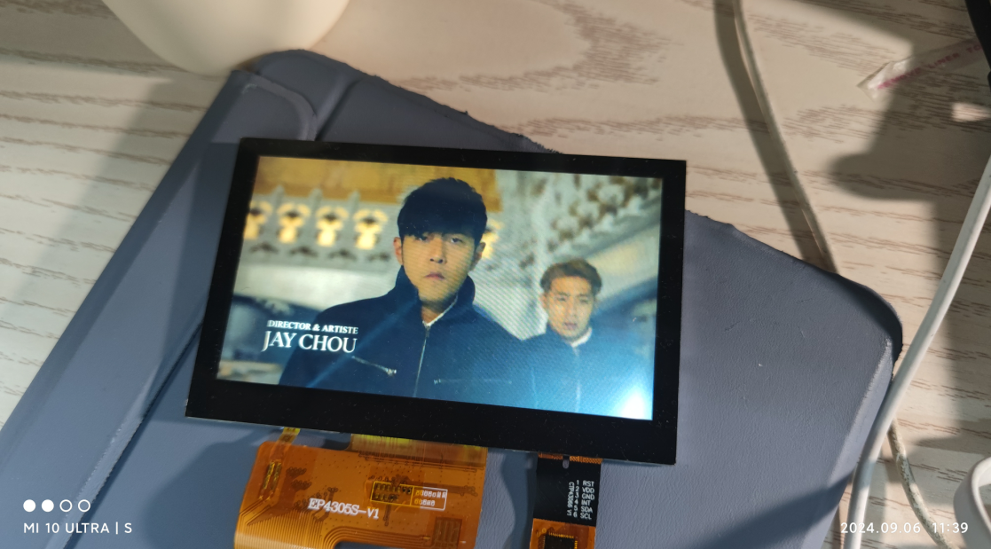
5. Test Photos:
MP3 Audio Playback: (using mplayer)

MP4 Video Playback: (mplayer, very laggy)
Qt4.8.7 Test:
WIFI Test: (very slow)

Regarding uploaded files:
First, the pre-compiled arm-qt & arm-tslib packages in the attachments at the end of the webpage can be directly extracted to the root file system for configuration;
the datasheet is the datasheet for the relevant chip (F1C100S has detailed register and interrupt information);
uboot, kernel, rootfs, compiler (gcc4.8.3), Qt4.8.7 source code, etc. are uploaded to Baidu Cloud Drive due to their large size. Address:
Files shared via cloud drive: f1C200s Link: https://pan.baidu.com/s/1v4qLWt4PDbzkcm0mK4IMMg?pwd=twtj Extraction code: twtj
armtslib.tar.gz
armqt.tar.gz
arm-2014.05-29-arm-none-linux-gnueabi-i686-pc-linux-gnu.tar.bz2
datasheet.zip
PDF_F1C200S Mini Linux Screen Development Board [Double-Layer Board + Qt4.8.7].zip
Altium_F1C200S Mini Linux Screen Development Board [Double-Layer Board + Qt4.8.7].zip
PADS_F1C200S Mini Linux Screen Development Board [Double-Layer Board + Qt4.8.7].zip
BOM_F1C200S Mini Linux Screen Development Board [Double-Layer Board + Qt4.8.7].xlsx
92425
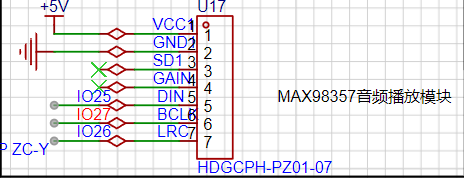
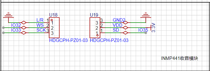
ESP32-based networked portable audio playback and positioning device
This project is a portable, location-based audio playback device built using an ESP32 microcontroller and my own GPS positioning module, OLED screen, amplifier, and speaker. It is programmed using VS Code and can perform basic positioning functions as well as connect to the internet to provide weather forecasts and play music.
1. Hardware Design:
The DC 12V power supply circuit uses the TL431 as the voltage regulator chip, and a filter capacitor is included to manage the current.

During actual use, it was found that the 250mA output current of the TL431 chip was insufficient to power numerous modules. Therefore, a three-way power supply was adopted, requiring the use of a voltage regulator chip with a larger output power capacity.
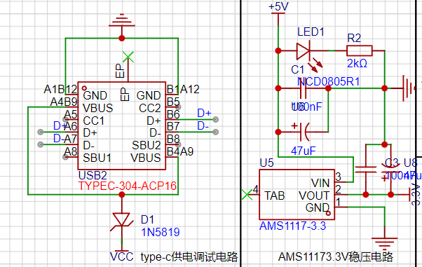
Type-C was considered for power supply and debugging, with an AMS1117-3.3 for 5V to 3.3V conversion and a CH340C for USB to serial port circuit design.
External module access:
The button

circuit uses an external debugging pin header.

This open-source project consists of two boards, an older and a newer one. The newer version is an improved board developed after issues were discovered during debugging.
Note: This project uses Platform.io for programming.
ESP32_MAIN.zip
esp32.mp4
PDF_ESP32-based Networked Portable Audio Playback and Positioning Device.zip
Altium_ESP32-based networked portable audio playback and positioning device.zip
PADS_ESP32-based Networked Portable Audio Playback and Positioning Device.zip
BOM_ESP32-based networked portable audio playback and positioning device.xlsx
92427
Waterwheel control panel
This device controls the rotation and LED changes of a waterwheel model. It can display the time or perform various LED changes while the waterwheel rotates. Equipped with a screen, it displays weather humidity and related information. The rotation speed and screen display can be adjusted via a rotary encoder. A photoresistor adjusts the overall brightness. (Implementation Stage)
1. Uses ESP32-WEOOM as the main controller, equipped with CH340C automatic download circuit.
2. Uses a DC-DC boost module to provide 12V power to the TB6612.
3. Uses off-the-shelf modules for the TB6612 to prevent burnout and replacement, or can be directly soldered to save size.
4. Two speed-regulating DC motor drive interfaces are provided, allowing simultaneous control of two DC motors. ![7028A4F2B4879DBD2FE13DAFD1F1A683.jpg]
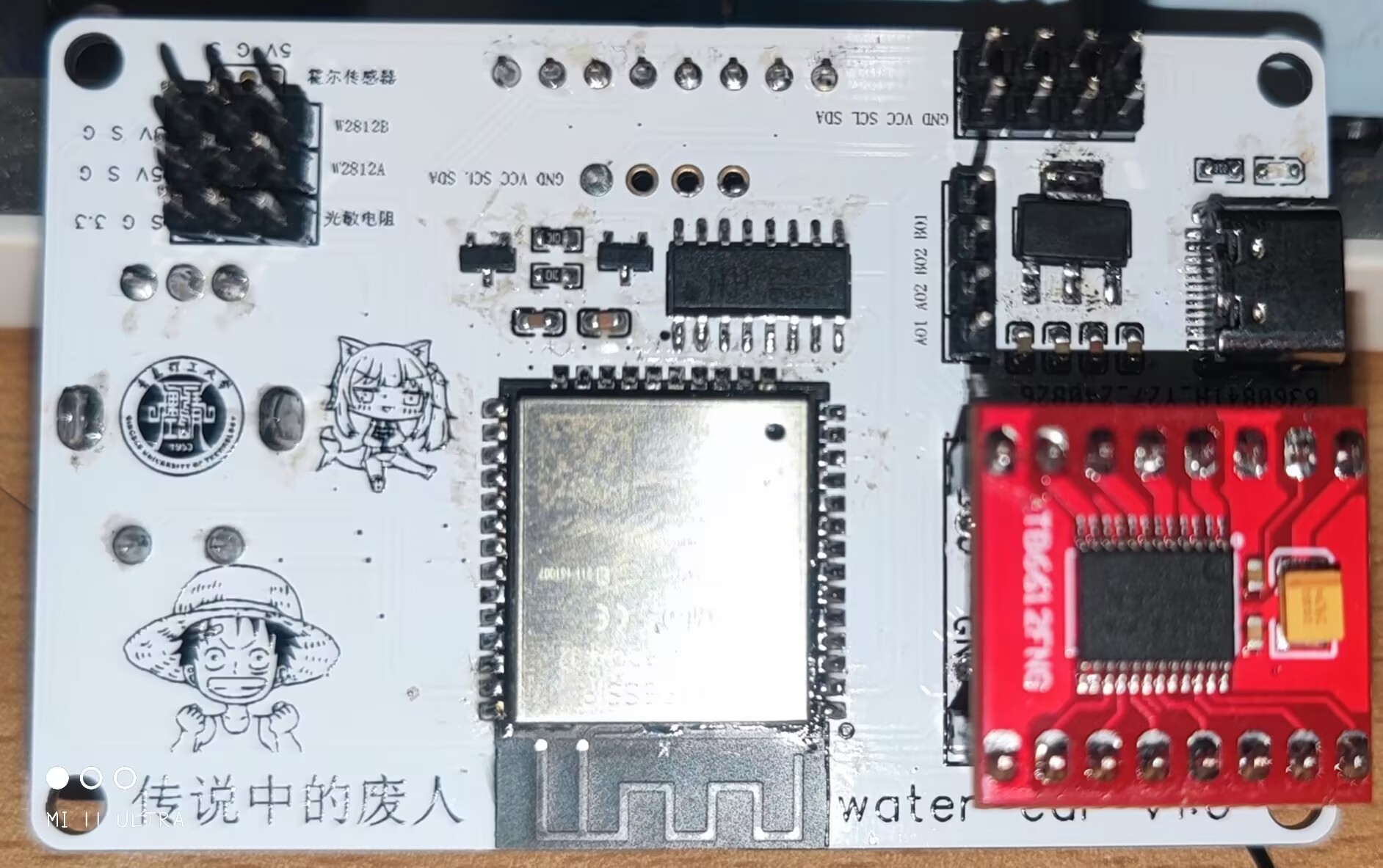
5. Two WS2812B control pins are provided.
6. Equipped with two I2C interfaces and one SPI interface.
7. Can be fitted with a 1.44 SPI screen or a 0.96 OLED screen for display.
![IMG_20240908_230946.jpg]
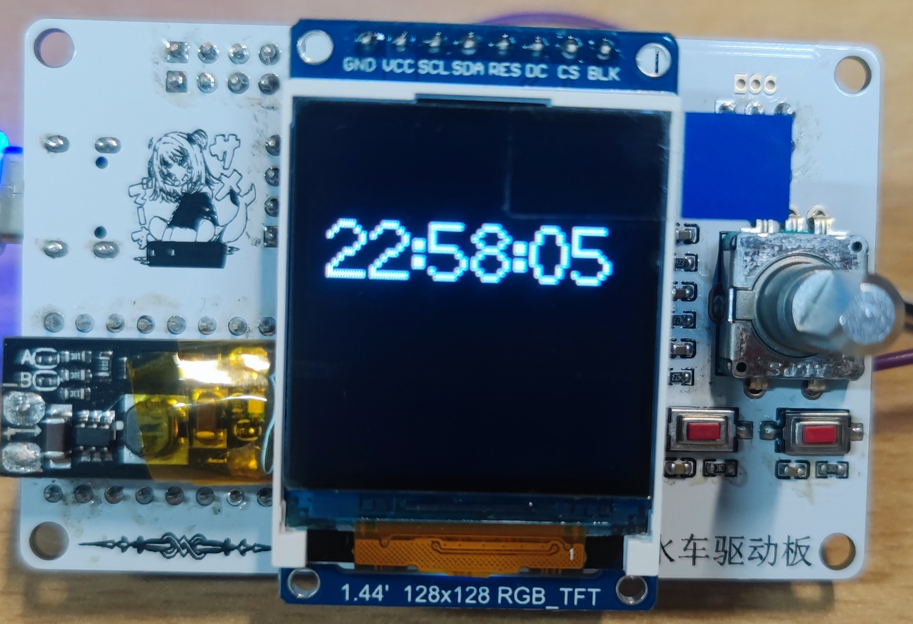
8. Includes an external EC11 rotary encoder.
Other: Also includes a light sensor interface and a Hall sensor interface.
Functions 1-8 have been verified. Due to time constraints, the light sensor and Hall effect sensor have not been verified.
Regarding the program:
the program currently only implements time display, LED strip control, and waterwheel speed adjustment via encoder.
Regarding the waterwheel:
due to excessive motor noise, a new motor is being selected to reduce noise.
Regarding the casing:
I intend to design it based on the waterwheel's shape, so the casing design will be implemented after the waterwheel verification is completed.
**The above related projects will be open-sourced sequentially after completion.
Apologies for the time constraints.
** The attached code is for testing purposes only!
VID_20240908_230134.mp4
VID_20240908_230355.mp4
sketch_aug31b.zip
PDF_Waterwheel Control Board.zip
Altium_Waterwheel Control Board.zip
PADS_Waterwheel Control Board.zip
BOM_Waterwheel Control Board.xlsx
92428
electronic
 ![IMG_20240908_145449.jpg]]
 II. Light Acquisition - PT3528BC-I6
 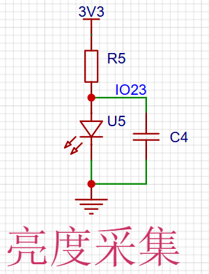 III. Independent Buttons
  IV. Display Device - 0.96 OLED
 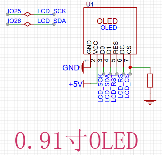 V. Buzzer Warning - MLT-5020
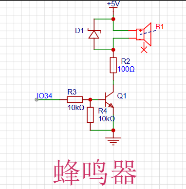
 VS-CODE + ESP-IDF. (PS: Software development is a lengthy process. While installing development tools, I crashed my computer, forcing me to reinstall the system. The development environment was only set up the day before the assignment was due, and the initial software development was completed. The final version requires further development, optimization, and improvement.)
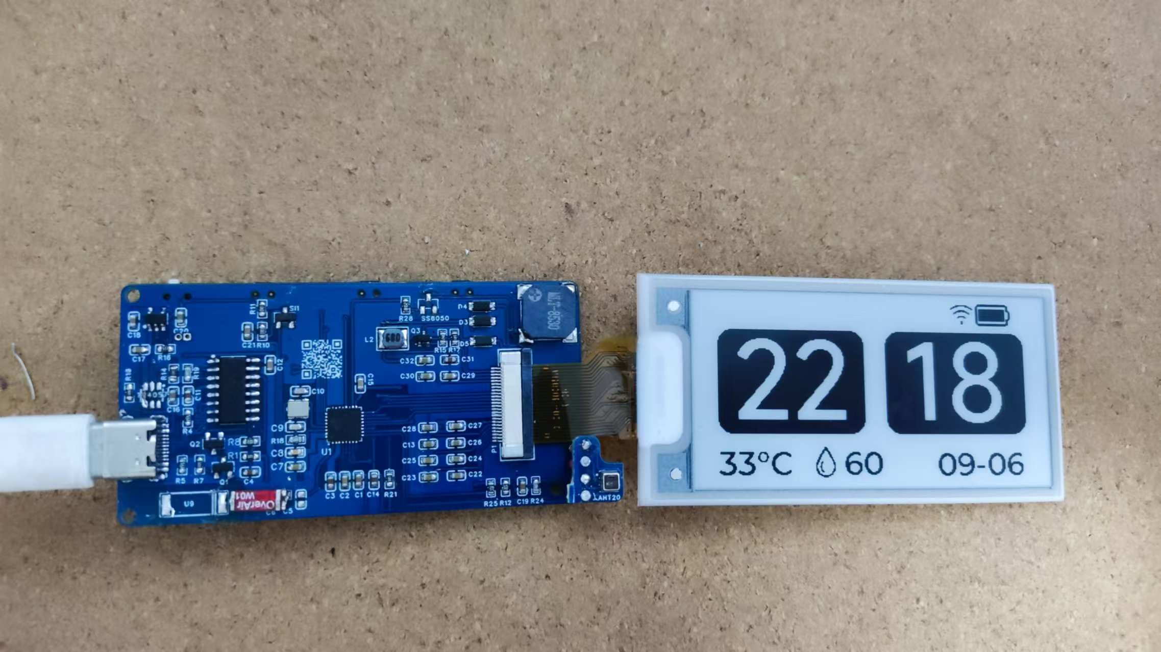


 京公网安备 11010802033920号

 E19-28-F-T-A-B-A-A-1


