This module is a cascaded HMC472 + HMC589, offering high-precision gain control with a gain/loss step of 0.5dB, capable of handling the amplification or loss requirements of most signal processing problems in electronics design competitions.
I personally used it in Problem C of the 2024 electronics design competition, and it worked exceptionally well in practice.
I bought the H3 using Xianyu (a second-hand marketplace app), it's the one with the cloud storage box.
Ideal for those wanting to learn Linux at a low cost.
The firmware is too large to upload here; join the group (757578508) to get it.
Ubuntu and Debian are available.
Note: After removing the core, apply a ring of low-temperature solder before using a heating pad to remove it; otherwise, the solder pads may come off.
Core board link:
[Xianyu link](https://m.tb.cn/h.gmuzAYJ?tk=4F4k3fUbgCF ZH4920) "Come grab a bargain! [Brand new Allwinner H3 development board, chip included, well-packaged, suitable for learning, includes casing and power supply]"
(Click the link to open directly)
Project Introduction:
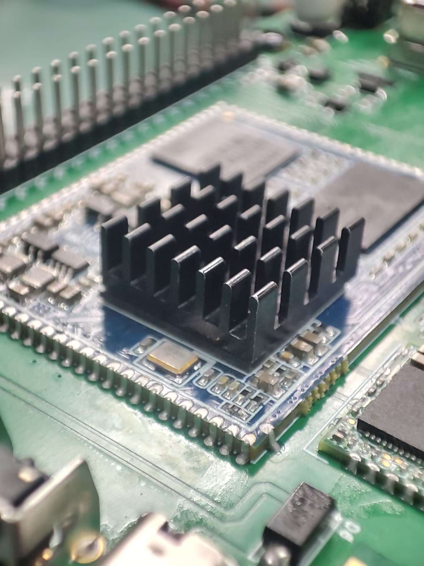
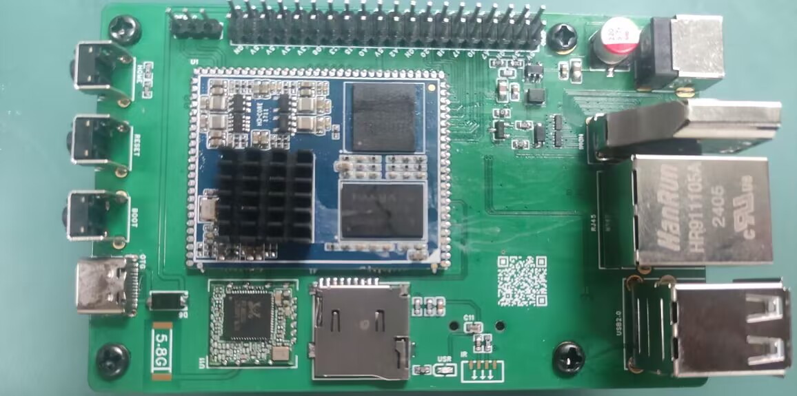
This project was inspired by an Allwinner H3 core board I found on Xianyu (a second-hand marketplace). I designed it as a baseboard, and all basic functions have been tested and are working normally.
The project
features several GPIO and serial ports. I also added a spare Wi-Fi module. Antennas can be found on Taobao, although they don't need to be soldered.
Project Parameters:
Storage is 256MB + 4GB, priced at 20 RMB including a charger, which is a great deal.
Principle Analysis (Hardware Description):
The schematic diagram of the core board is from the official website. I replaced some components and laid out the layout myself.
The software code
is the official firmware, and it works quite well.

1. Firmware Burning Tutorial: First, burn the firmware to the SD card
. 2. Log in as root user. Do not log in first and then su root (I've already encountered this problem).
3. Execute in the terminal: nand-sata-install
4. Select 2 Boot from eMMC - system on eMMC
5. A prompt will pop up asking to erase the data on the eMMC. Select Yes
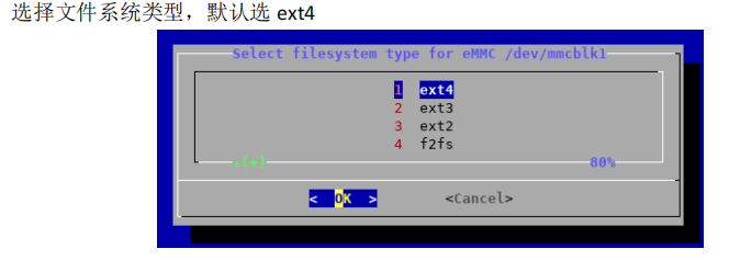
6. Select the file system type. The default is ext4.
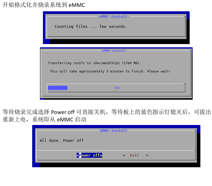
7. Begin formatting and burning the system to eMMC.
8. Wait for burning to complete. Select "Power off" to shut down the device. After the blue indicator light on the board goes out, you can remove the TF card and power on again. The system will then boot from eMMC.
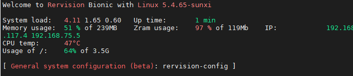
WiFi should boot normally and IP address should be obtained correctly.

Note:
Network port should be normal,
USB port should be normal,
serial port should be normal,
WiFi should be normal,
debug should be present, silkscreen printing is not applied.
PDF_Allwinner H3.zip
Altium_AllwinnerH3.zip
PADS_AllwinnerH3.zip
BOM_AllwinnerH3.xlsx
92526
USB 2.0 expansion dock (3*USB + 2*UART + 1*STlink)
Originally, I was using a regular docking station for debugging, which had two serial debuggers and an ST-Link connected to it. However, it looked messy, and it seemed that there weren't any products on the market that combined two serial ports and an ST-Link. So, I created this USB docking station.
First, I would like to thank engineer Chen Zhe for his STlink open-source project:
https://oshwhub.com/CYIIOT/ST_LINK-V2_1.
This project uses two ICs:
1. FE2.1 (USB 1-to-7 expansion chip)
2. STM32F103CBT6 (I personally tested that the C8T6's memory is too small, and the firmware cannot be burned).
The functions are as follows:
1. Two * USB 2.0 + USB 2.54 interfaces (used for direct USB debugging with DuPont wires)
2. Two * UARTs (sometimes two serial ports are used to control two microcontrollers respectively)
3. STlink programming interface (only SWDIO and SWCLK)
. All components are surface-mount components. This allows for a direct setup using a heating platform, and also provides stability and a more comfortable viewing experience when placed on a table.
The pin order for burning firmware from top to bottom is (3V3, SWCLK, SWDIO, GND).
STLinkV2.J28.M18_Firmware.zip
PDF_USB2.0 Expansion Dock (3 USB + 2 UART + 1 STlink).zip
Altium USB 2.0 Dock (3 USB + 2 UART + 1 STlink).zip
PADS_USB2.0 Dock (3 USB + 2 UART + 1 STlink).zip
BOM_USB2.0 Dock (3 USB + 2 UART + 1 STlink).xlsx
92527
Linear magnetic axis keyboard - Hanmei
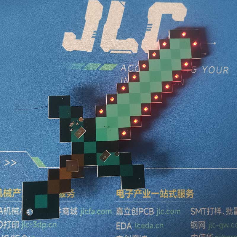
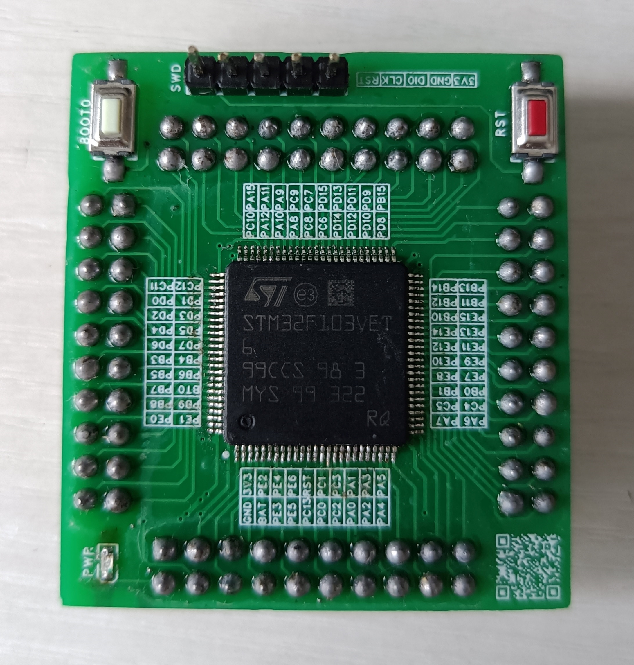
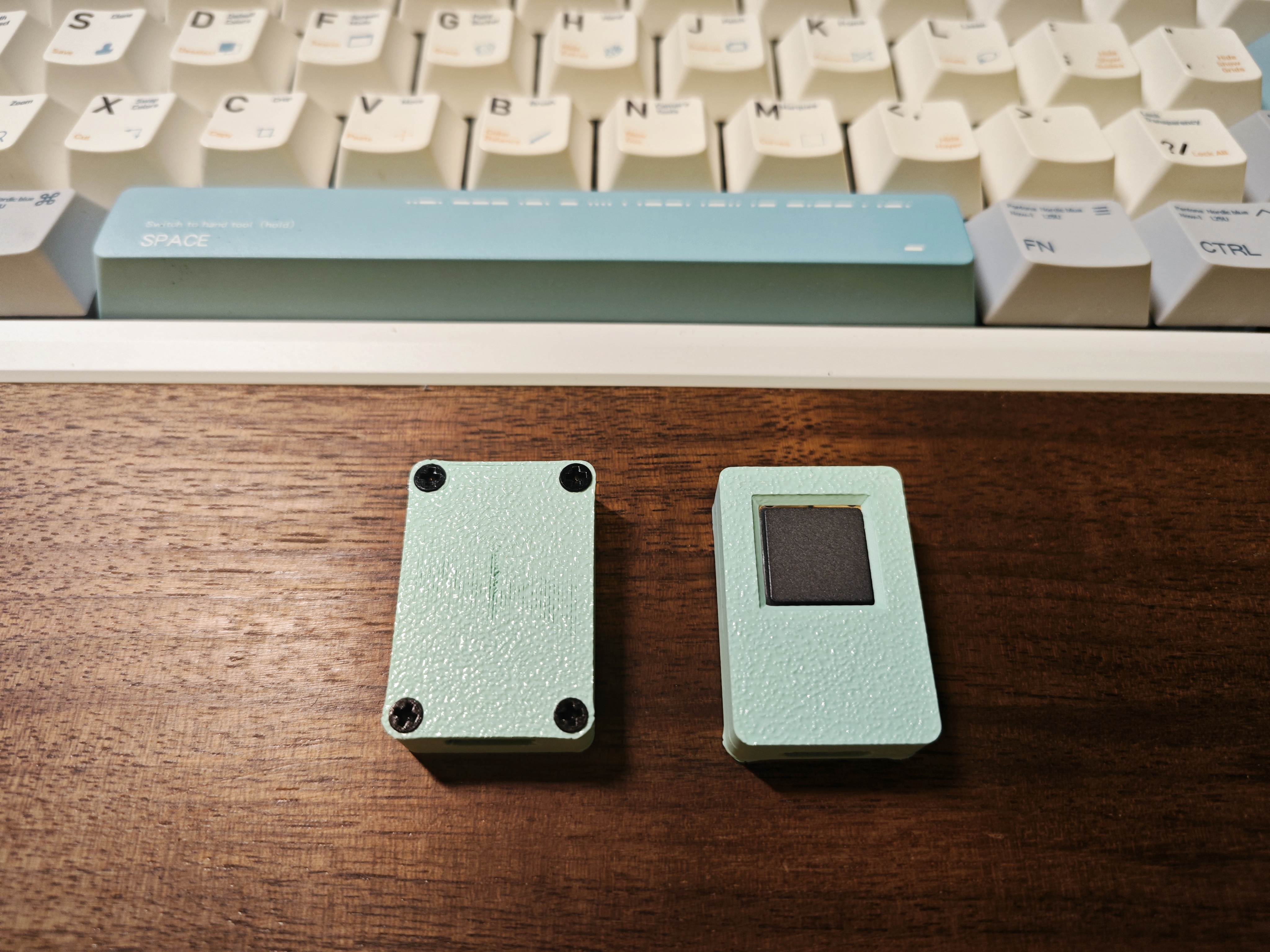
The fragrance of plum blossoms comes from the bitter cold, hence the name "Winter Plum" (寒梅). This is a simplified version of a linear magnetic axis keyboard designed using an IC in an LQFP32 package.
The name "Hanmei" (寒梅, meaning "Winter Plum") comes from the Chinese proverb "The fragrance of plum blossoms comes from the bitter cold." This is a low-cost linear magnetic keyboard designed using the AT32F425K8T7 microcontroller in an LQFP32 package, paired with a low-cost linear Hall effect sensor 49E. The design precision is 0.5mm. The schematic is a 6x18 matrix (actual maximum 6x15), which can be modified to layouts of 98 keys or less (maximum 108 keys; making a 104-key layout requires moving many unused keys, which is cumbersome; layouts of 98 keys or less are only recommended). A 61-key binary firmware is also provided for DIY projects.
The communication protocol is a custom OpenAgreementHID (OHID) protocol, which will be updated periodically. The attached OHID protocol document can be used to write your own host computer.
Note: The prototype uses a front-mounted iridescent package; you can modify it to a reverse-mounted package.
Technical exchange group:

OpenAgreementHID_0603.pdf
PDF_Linear Magnetic Axis Keyboard - Hanmei.zip
Altium Linear Magnetic Axis Keyboard - Hanmei.zip
PADS Linear Magnetic Axis Keyboard - Hanmei.zip
BOM_Linear Magnet Keyboard - Hanmei.xlsx
92528
electronic


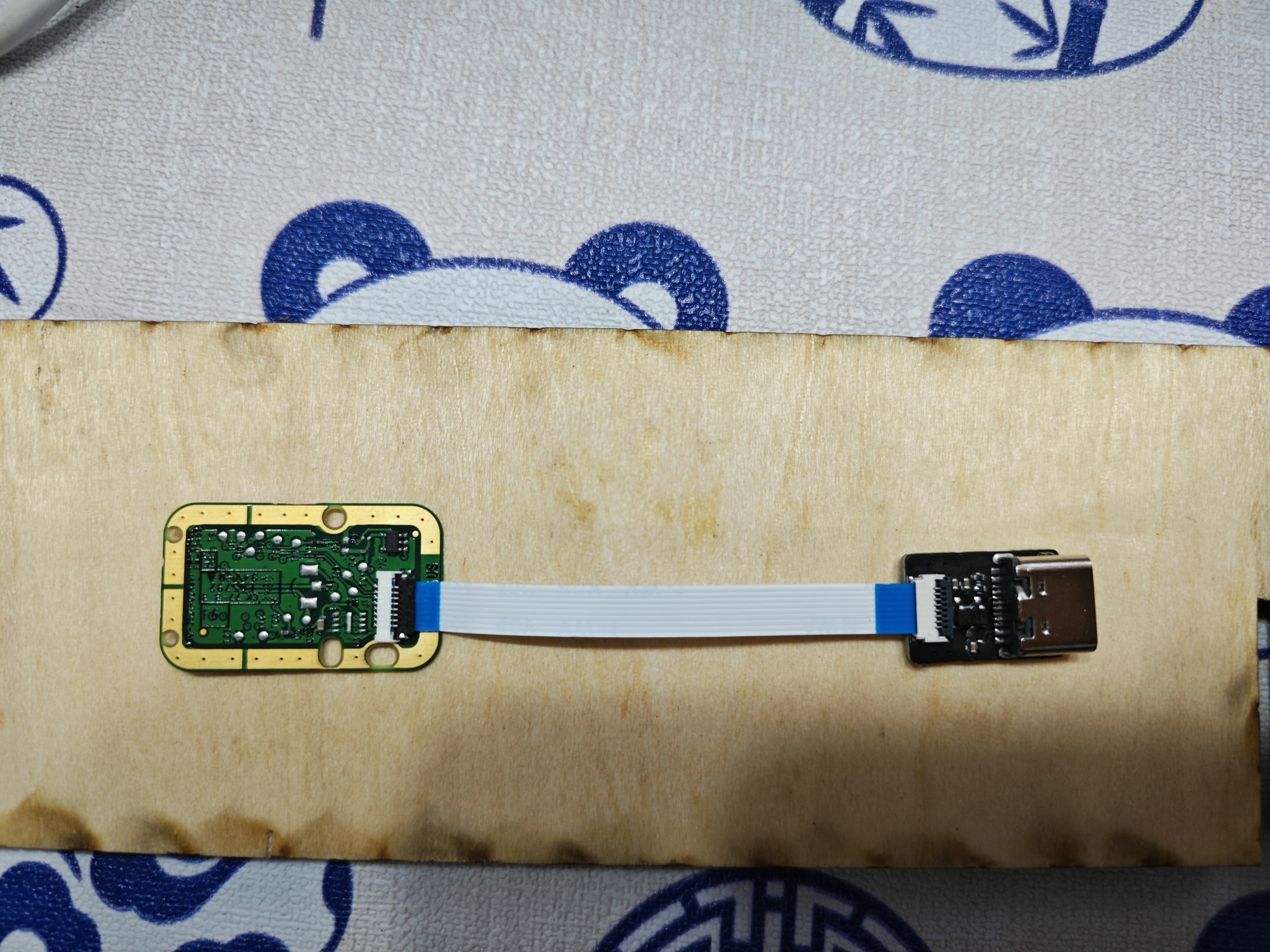
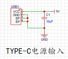 Since there is no data transmission requirement, a 2-pin Type-C direct-plug interface was chosen for easy soldering and a simple circuit.
 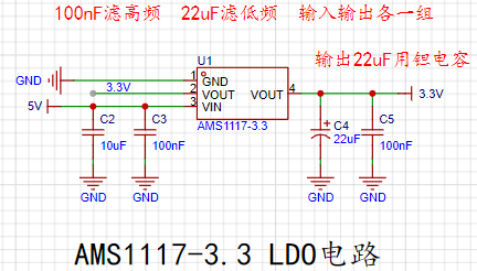 has two capacitors connected to both the input and output: one to filter high frequencies and the other to filter low frequencies. According to the datasheet, a 22uF tantalum capacitor is required at the output. The datasheet specifies this as follows:
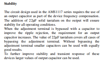
 a simple LED circuit using a 1kΩ resistor. However, in actual use, the brightness was found to be somewhat excessive. Trying a 5kΩ or 10kΩ resistor might yield a more suitable brightness.
  is a single-row bent-pin output interface, connected using DuPont wires.
 3.3V Output:
 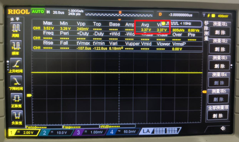 3.3V Output Ripple:

 This is a C-language IOT-Router
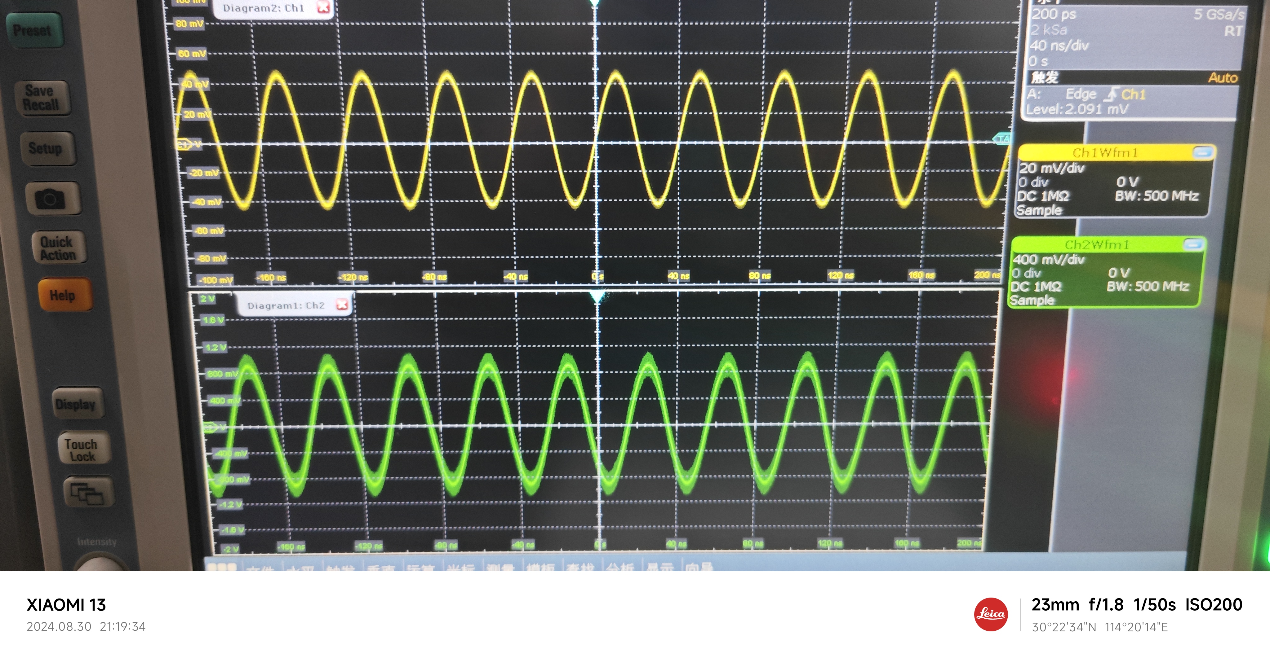


 京公网安备 11010802033920号

 HLMP-1520-RW000


