I. Project Introduction
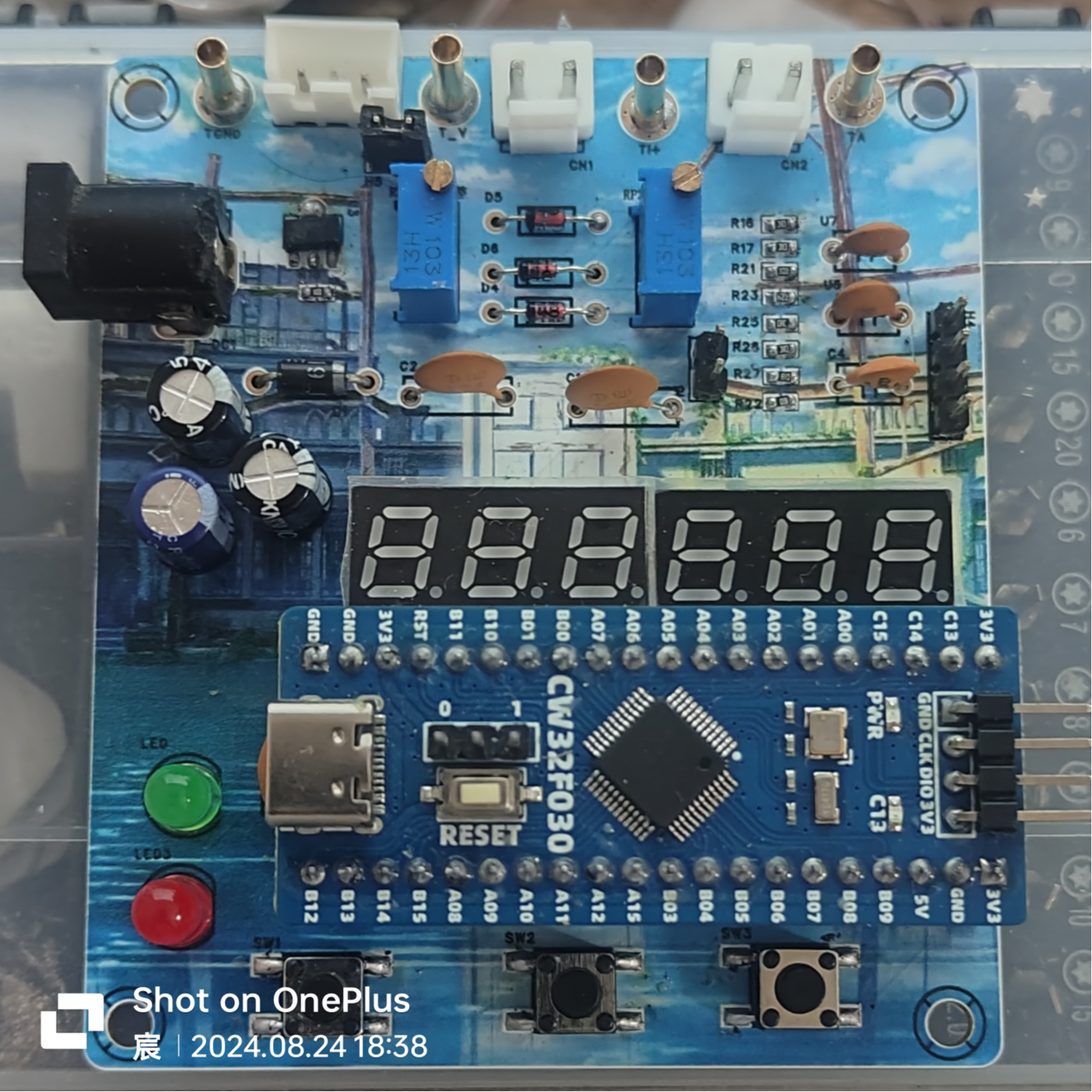
Input DC 5-35V, power circuit incorporates 1N5819 with reverse connection protection. This project achieves the following functions: 1. Voltage measurement: 0-30V 2. Current measurement: 0-3A 3. Voltage calibration: 3V, 8V, 15V 4. Current calibration: 0.5A
, 1.5A II. Button and Mode Introduction
SW1: Switch Mode SW2: Calibration SW3: Return to
Mode 0 Function: General measurement. Left digital tube displays voltage value, right digital tube displays current value.
Mode 1 Function: 3V calibration. Left digital tube displays V.03, right digital tube displays voltage value.
Mode 2 Function: 8V calibration. Left digital tube displays V.08, right digital tube displays voltage value.
Mode 3 Function: 15V calibration. Left digital tube displays V.15, right digital tube displays voltage value.
Mode 4 Function: 0.5A calibration. Left digital tube displays A.0.5, right digital tube displays current value.
Mode 5 Function: 1.5A calibration. Left digital tube displays A.1.5.
When calibrating the current value displayed on the right digital tube, do not solder R0.
When calibrating the voltage, use a jumper cap connected to H5. Use a multimeter in voltage mode, connect the red probe to T_V and the black probe to TGND. Adjust RP1 and press the calibration button. For example, to calibrate 3V, connect the multimeter, power on the board, and adjust RP1 until the multimeter displays 3V. Press the calibration button. Repeat this process for subsequent
calibrations. When calibrating the current, use a jumper cap connected to H6. Use a multimeter in voltage mode, connect the red probe to TI+. Connect the black probe to TGND and adjust RP2 so that the multimeter reading multiplied by 10 equals the current to be calibrated, for example, to calibrate 0.5A. Connect the multimeter, power on the board, and adjust RP2 until the multimeter displays 0.05V. Press the calibration button and repeat the process. When
measuring voltage, connect the jumper cap to H5 and H3 sockets. The left side is negative and the right side is positive. Connect the jumper cap to the object being measured, and the voltage value will be displayed on the left digital display.
When measuring voltage, connect the jumper cap to H6 and CH1 sockets. The left side is negative and the right side is positive. Connect the jumper cap to the object being measured, and the current value will be displayed on the right digital display.
III. Firmware Burning
1. Firmware: Project.hex in the attachment
2. If using Keil to burn the .hex file:
Step 1: Create a CW32 project
Step 2: Click the magic wand and find output
Step 3: In output, click Select Folder for Objects... on the left and set the path to the downloaded .hex file
in the attachment Step 4: In output, click Name of Enter the full name of the downloaded .hex file in the Executable box (remember to include the filename extension).
Step five is the normal burning process.
A demonstration video is available in the attachment.


 京公网安备 11010802033920号

 XC6124E618ML


