This project designed a digital voltmeter and ammeter based on the Diwenxing CW32F030C8T6 microcontroller. The device utilizes high-precision ADC technology to convert analog voltage and current signals into digital displays, providing intuitive and accurate measurement results. Its main features include:
employing a high-resolution ADC to ensure the accuracy of voltage and current measurements;
using the domestically produced Wuhan Xinyuan Semiconductor CW32 as the main controller, while also being compatible with other similar development boards,
supporting multiple measurement modes, and suitable for different application scenarios.
Multiple protection measures are incorporated into the design to ensure stable operation of the device in various environments.
This digital voltmeter and ammeter can be used for education and training, helping learners to gain a deeper understanding of circuit and measurement techniques.
I. Project Introduction
An ADC (Analog-to-Digital Converter) is an indispensable key component in electronic systems. It converts continuous analog signals into digital signals, enabling digital processing and analysis. ADCs play a crucial role in signal conversion, measurement and data acquisition, control system input, and communication and signal processing. Their widespread application promotes the intelligent and precise control of electronic equipment across various industries, and is one of the key factors driving modern technological progress.
Digital voltmeters and ammeters combine ADC technology with circuit measurement principles, accurately converting analog voltage and current signals into digital displays for easy reading and analysis by electronic engineers. This device not only improves the accuracy and efficiency of circuit measurements but also helps engineers better understand circuit behavior, making it a powerful tool for electronic design and troubleshooting, and playing a vital supporting role in the work of electronic engineers. In product applications, digital voltmeters ensure the accuracy and safety of circuit design, while also providing strong support for product quality control and subsequent maintenance.
II. Principle Analysis (Hardware Description)
1. Power Supply Circuit
LDO (Low Dropout Linear Regulator) Selection
This project uses an LDO as the power supply. Considering that most voltmeter products are used in industrial scenarios with 24V or 36V power supplies, the SE8550K2 with a maximum input voltage of up to 40V was selected as the power supply. The main reason for not using a DC-DC step-down circuit to handle the large voltage drop is to avoid introducing DC-DC ripple interference during the design process; a secondary reason is to reduce project costs.
2. Voltage Sampling Circuit
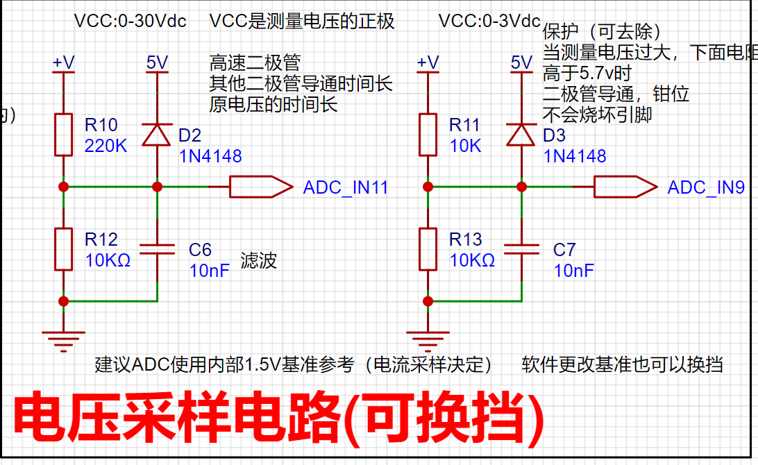
The voltage divider resistors in this project are designed to be 220K+10K, so the voltage division ratio is 22:1 (ADC_IN11).
Voltage divider resistor selection
(1) The maximum value of the designed measurement voltage. For safety reasons, this project is 30V (the actual maximum can be displayed as 99.9V or 100V);
(2) ADC reference voltage. In this project, it is 1.5V. This reference voltage can be configured through the program;
(3) Power consumption. In order to reduce the power consumption of the sampling circuit, the low-side resistor (R7) is usually selected as 10K based on experience; 3.
Current Sampling Circuit
This project uses a low-side current sampling circuit for current detection. The sampling current designed for the low side of the sampling circuit and the development board meter interface
is 3A. The selected sampling resistor (R0) is 100mΩ.
The sampling selection mainly needs to consider the following aspects:
(1) The maximum value of the pre-designed measurement current. In this project, it is 3A
; (2) The voltage difference caused by the current sensing resistor. It is generally not recommended to exceed 0.5V.
(3) The power consumption of the current sensing resistor should be selected according to the appropriate package. Considering the power consumption (temperature) problem under high current, a 1W packaged metal wire-wound resistor was selected in this project.
(4) The amplification factor of the voltage across the current sensing resistor: No operational amplifier was used to build the amplifier circuit in this project, so the amplification factor is 1.
III. Precautions
: Do not solder R0 during testing!
Video Link:
https://www.bilibili.com/video/BV18CWZeAEPG/
Project Introduction:
Thanks to LCSC and CW32 for providing this free training camp, and thanks to Engineer Li for the hardware explanation. The hardware explanation was very detailed, and I highly recommend it to beginners. The completion level this time is not as good as other experts. It's a pity that I didn't design a 3D shell and panel. I didn't think of LCSC's 3D shell design function at the time. It is quite suitable for beginners and very useful. In addition, SW was not downloaded at the time, so I didn't design
the project function
. Define 5 working modes. K1 is used to switch display modes. K2 sets the parameter value of the corresponding mode and saves it to FLASH. K3 returns to mode 0.
Mode 0: Displays normal voltage and current values (the next row of digital tubes displays the voltage value .V or .V automatically switches, the previous row displays the current value _.**A).
Mode 1: Voltage 5V calibration value setting. The next row of digital tubes displays 5.05. The previous row displays the current voltage value _.V or ._V. In this mode, the multimeter should be set to 5.00V when measuring the measured bit. After pressing the K2 key, the current value is calibrated as a 5V voltage value.
Mode 2: 15V voltage calibration setting. The next row of the digital display shows 5.15. The previous row displays the current voltage value as _V or ._V. In this mode, the multimeter should be set to 15.0V when measuring the measured bit. After pressing the K2 key, the current value is calibrated as a 15V voltage value.
Mode 3: 0.5A current calibration setting. The next row of the digital display shows A.0.5. The previous row displays the current current value as _.**A. After pressing the K2 key, the current value is calibrated as a 0.5A current value.
Mode 4: 1.5A current calibration setting. The next row of the digital display shows A.1.5. The previous row displays the current current value as *.**A. After pressing the K2 key, the current value is calibrated as a 1.5A current value.
Project Parameters
: Measurable Voltage: 0-30V;
Measurable Current: 0-3A.
Principle Analysis (Hardware Description)
: Power Supply Circuit:
This project uses an LDO as the power supply. Considering that most voltmeter products are used in industrial scenarios with 24V or 36V power supplies, this project selected the SE8550K2 with a maximum input voltage of up to 40V as the power supply. The main reason for not using a DC-DC step-down circuit to handle large voltage differences is to avoid introducing DC-DC ripple interference during the design process; a secondary reason is to reduce project costs.

Voltage Sampling Circuit:
The voltage divider resistors in this project are designed to be 220K+10K, therefore the voltage division ratio is 22:1 (ADC_IN11).
The voltage divider resistor selection
is designed to measure the maximum voltage value. For safety reasons, this project uses 30V (the actual maximum display value can be 99.9V or 100V).
The ADC reference voltage is 1.5V in this project, and this reference voltage can be configured through the program.
To reduce the power consumption of the sampling circuit, the low-side resistor (R7) is usually chosen as 10K based on experience.
Then, the high-side resistance of the voltage divider resistor can be calculated using the above parameters.
The required voltage division ratio is calculated, i.e., the ADC reference voltage. The input voltage is designed; using known parameters, 1.5V/30V = 0.05 can be calculated.
The high-side resistance is calculated as the low-side resistance/voltage division ratio; using known parameters, 10K/0.05 = 200K can be calculated.
A standard resistor is selected: a resistor slightly higher than the calculated value of 200K is chosen. We usually choose E24 series resistors; therefore, in this project, 220K, which is greater than 200K and closest to the calculated value, is selected.
If, in actual use, the voltage to be measured is lower than 2/3 of the module's design voltage (66V), the voltage divider resistor can be replaced and the program modified to improve measurement accuracy. The following example illustrates this:
Assuming the measured voltage is no higher than 24V and other parameters remain unchanged,
calculations show 1.5V/24V = 0.0625, 10K/0.0625 = 160K. 160K is a standard E24 resistor and can be directly selected, or a higher value 180K can be chosen with some redundancy.
If, in actual use, the voltage to be measured is higher than the module's 99V design voltage, a different resistor can be selected. To achieve a wider voltage measurement range, one can choose to replace the voltage divider resistor or modify the reference voltage. The following example illustrates this:
Assuming the measured voltage is 160V, the solution is to increase the voltage reference to expand the range.
Given that the voltage division ratio of the selected resistor is 0.0145, we can calculate 160V * 0.0145 = 2.32V using the formula. Therefore, we can choose a 2.5V voltage reference to expand the range (increasing the range will reduce accuracy).
Considering the potential fluctuations in the measured power supply, a 10nF filter capacitor is connected in parallel with the low-side voltage divider resistor to improve measurement stability.
Range switching:
In this project, an additional voltage sampling circuit was added. Therefore, we can discuss the significance of range switching for improving measurement accuracy. Multimeters often have multiple range settings for more accurate measurements. By adjusting different ranges, the optimal measurement accuracy of the measured point within the corresponding range can be obtained.
This project requires a combination of hardware and software to achieve this function. When we first use the ADC_IN11 channel mentioned earlier to measure voltages below 30V... If the measured voltage is within 0~3V, the ADC_IN9 channel is used for measurement. At this time, due to the reduced voltage division ratio, the measurement accuracy is greatly improved.
There are many ways to implement gear shifting, and the development board design provides more design possibilities.
Current sampling circuit
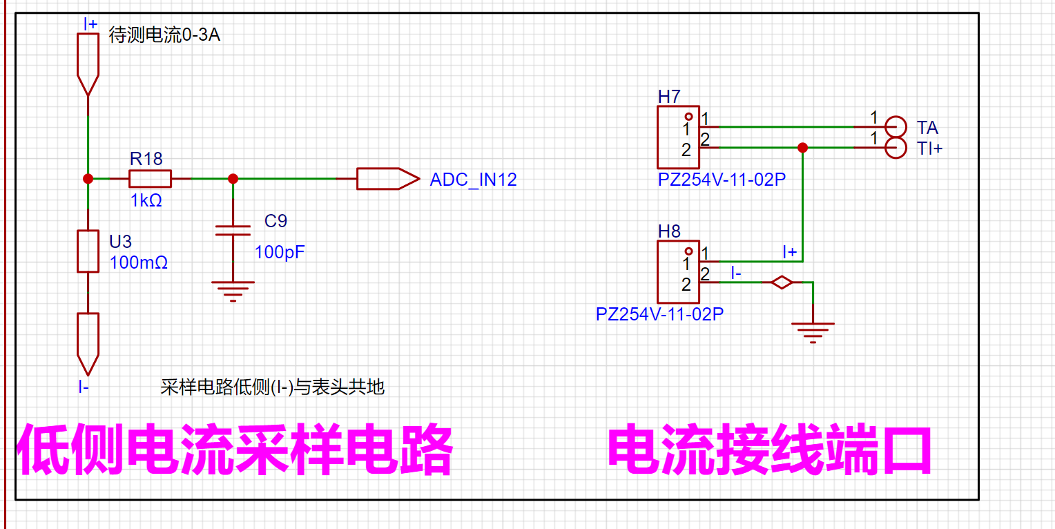
design analysis:
The sampling current in this project is 3A, and the selected sampling resistor (R0) is 100mΩ.
The sampling selection mainly needs to consider the following aspects:
the maximum value of the pre-designed measurement current,
the voltage difference brought by the 3A current sensing resistor in this project, generally not recommended to exceed 0.5V
; the power consumption of the current sensing resistor should be selected according to this parameter. Considering the power consumption (temperature) problem under high current, a 1W packaged metal wire-wound resistor was selected in this project;
the voltage amplification factor of the current sensing resistor: no operational amplifier was used to build the amplification circuit in this project, so the factor is 1.
Then the current sensing resistance value can be calculated using the above parameters. Selection:
due to This project does not use an amplifier circuit, therefore a larger sampling resistor is needed to obtain a higher measured voltage for measurement.
Considering that a larger resistor would result in a larger voltage drop and higher power consumption, an unlimited selection of a larger resistor is not feasible .
This project uses a 1W package resistor, corresponding to a power consumption of 1W.
Based on the above data, a 100mΩ current-sensing resistor was chosen. According to the formula, 3A * 100mΩ = 300mV, 900mW.
To handle different operating environments, especially high-current scenarios, the R0 resistor can be replaced with constantan wire or a shunt. The choice of alternative can be based on the specific application scenario. For safety and educational purposes, this project will not discuss measurements exceeding 3A, but the principle remains the same.
Precautions
Actually, the beginning was basically the same as in the training camp. The difference was that I chose surface mount components for most of them. To be honest, I was hesitant to choose surface mount components initially, but thanks to the answers from the experts in the group, I decided to. These past few days, while doing physical verification, I saw Li Gong say in a new video that people are just a little afraid. As long as you pay attention to the parameters you chose beforehand, just boldly select and use the components. I really understand this. The fear of not choosing was just because I was afraid of not doing it well. But what if I don't do it well? I can just draw another version, haha. Another difference is that I chose to directly lay copper instead of single-point grounding. Later, I heard from Li Gong that the current sampling resistor area is the power ground, so I directly implemented ground isolation (I think that's fair). Then I asked a senior student, who said it wasn't a big problem, so I did it that way. Thanks again to my brother Long for his help. Let
me also ramble on about the small troubles and insights I encountered during these few days of physical verification.
Although Li Gong suggested that we should still learn about CW32 development, I chose to just abandon it and directly burn the official program. Actually, when burning Example 9, there's no need to skip soldering the current sampling resistor; just solder it on directly. Then you can adjust it directly using a voltage and current source.
This time I only just realized that digital tubes come in so many sizes. When buying one, be sure to check the display size carefully.
Also, if your multimeter is like mine, when measuring current, be sure to move the green probe to the left current setting, otherwise you won't get a reading
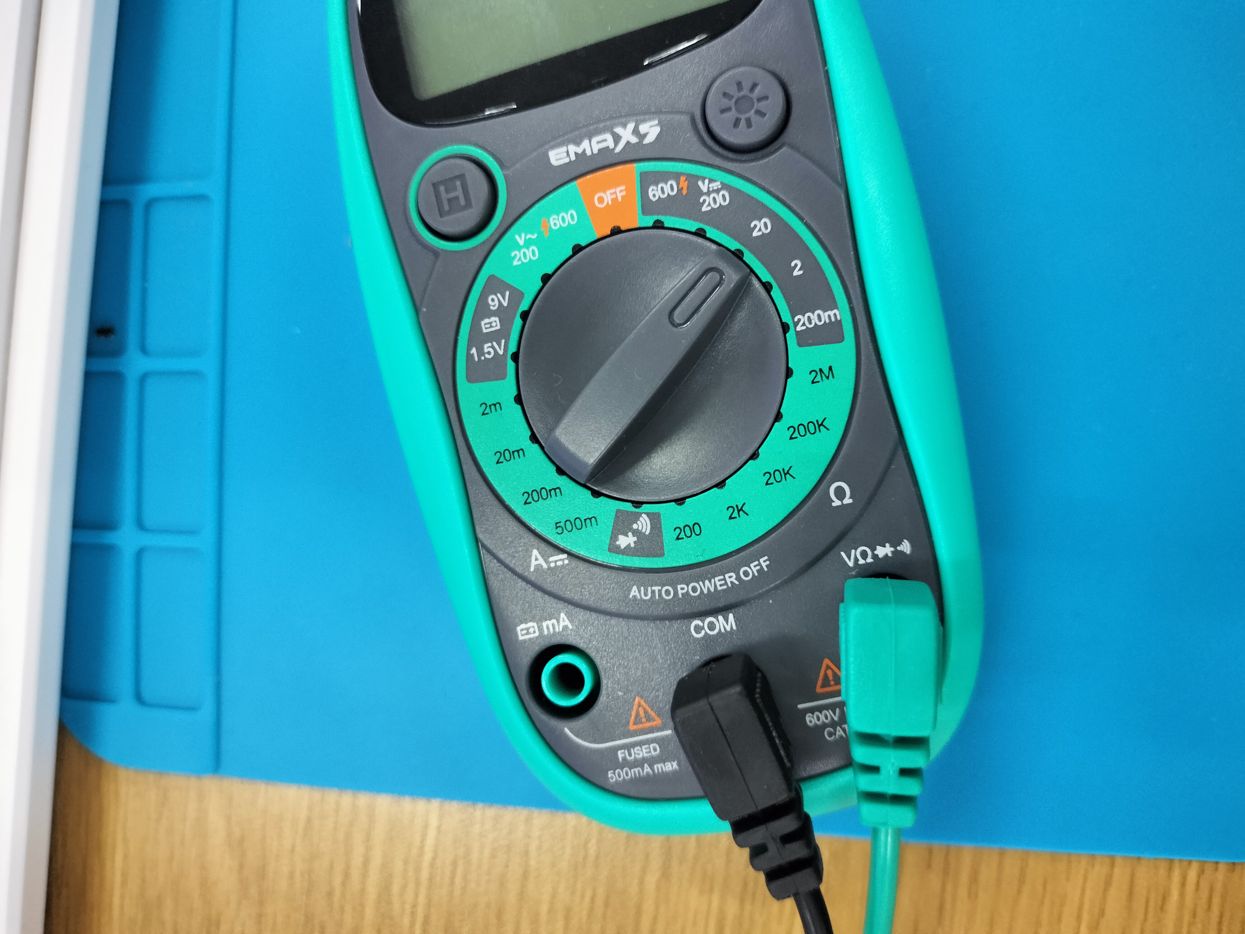
. Oh, and the connector—don't choose a pin header like I did. Although thin DuPont wires can handle 3A, it's really inconvenient.
After buying the components, I realized I forgot to buy a monolithic capacitor. Later, following Yunmo's advice, I replaced the monolithic capacitor with a ceramic capacitor I had on hand, and it worked perfectly.
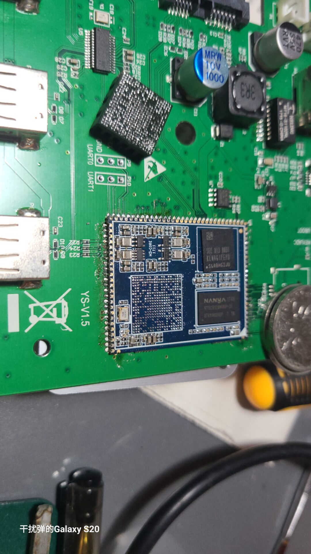
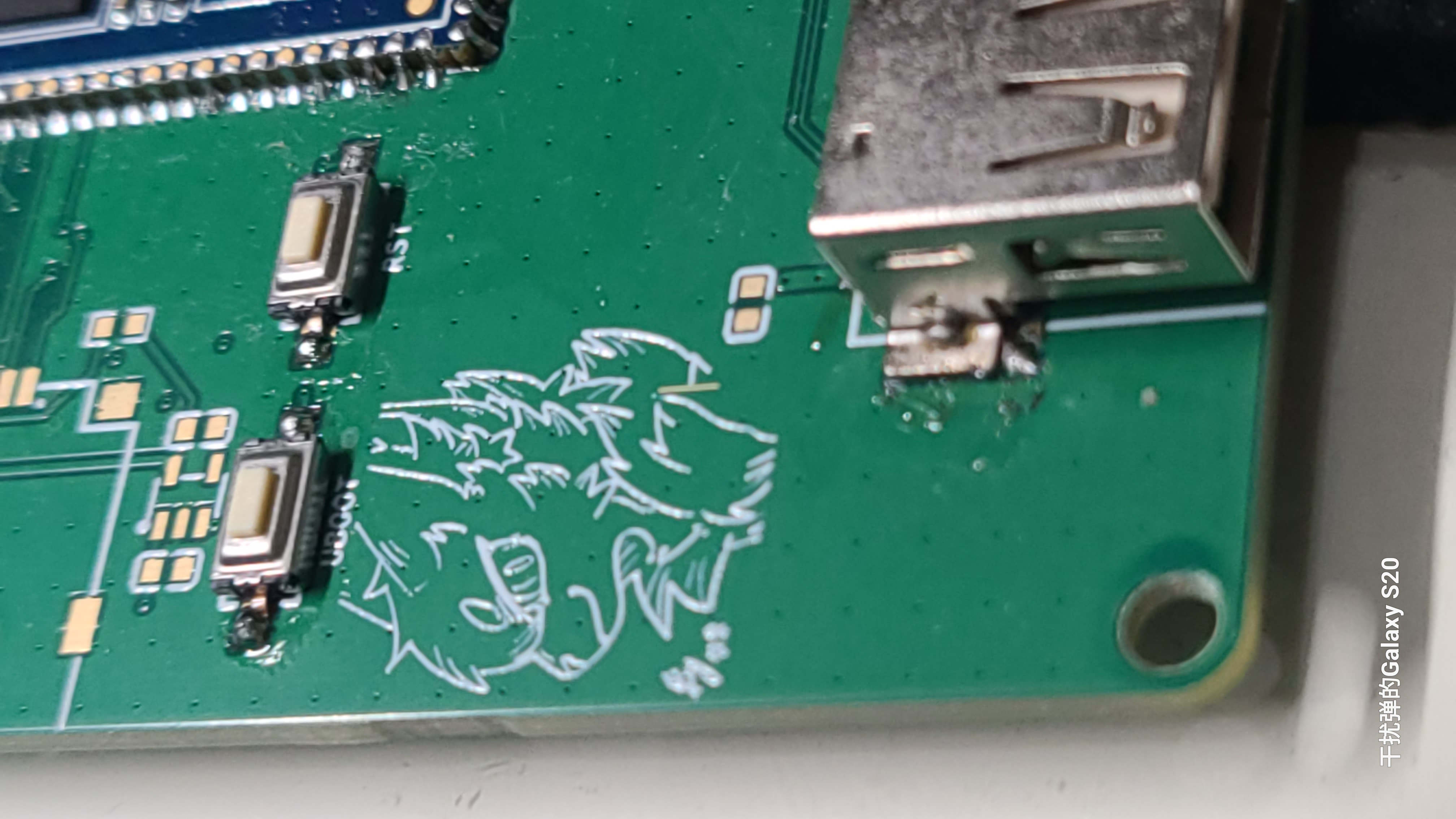
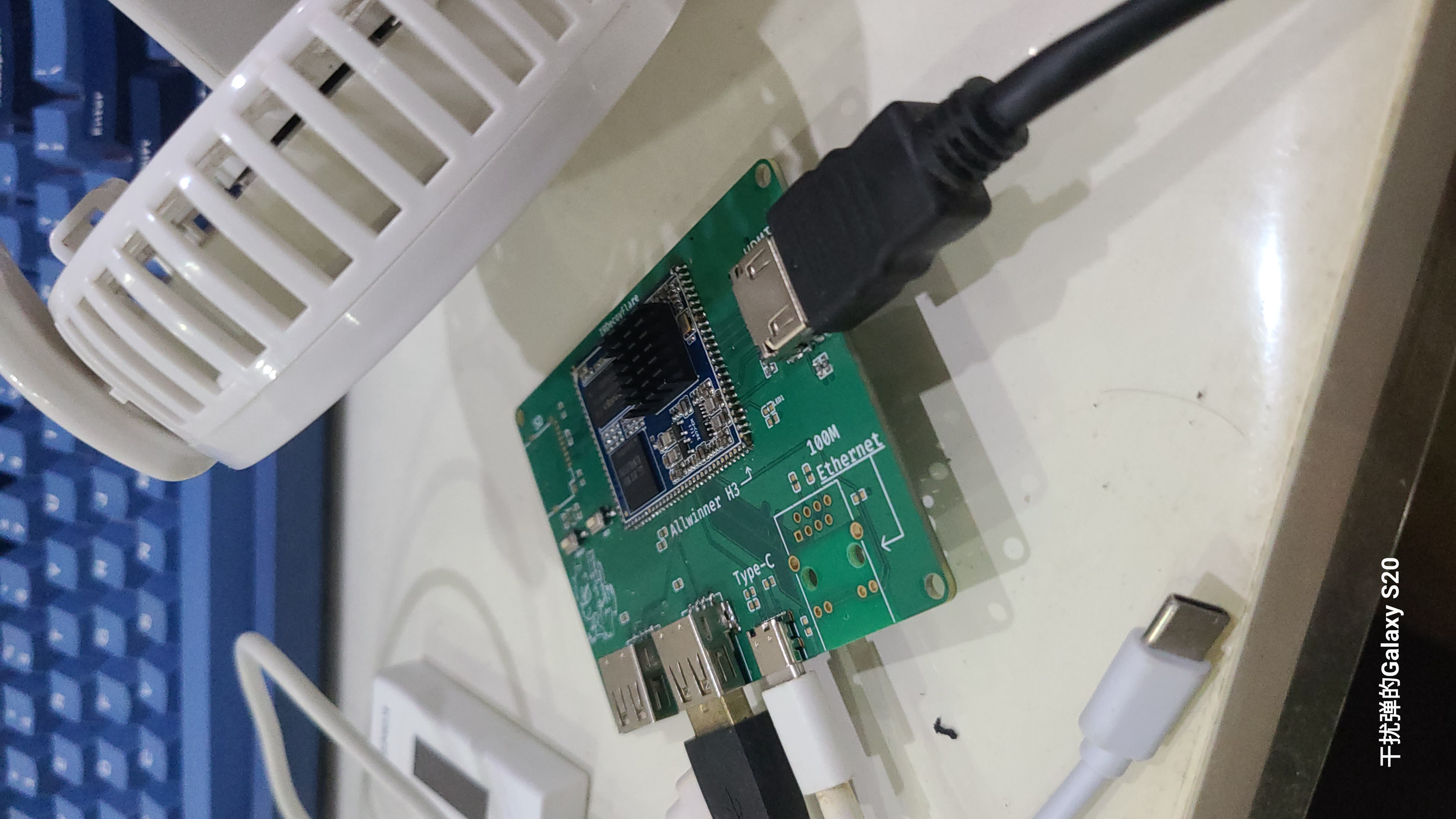
Based on the 19.9 RMB core board from Xianyu (a Chinese online marketplace), the peripheral circuitry has been simplified to include an HDMI port, making it suitable for use as a server.
Cheap core boards from Xianyu (a second-hand marketplace) are often reused. There's not much to introduce here
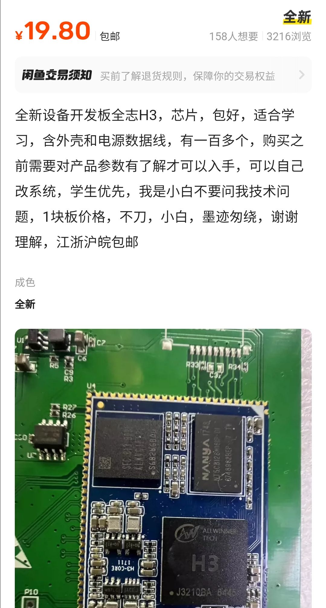
. It's worth noting that before disassembling the core board, remember to apply a layer of low-temperature solder and then heat it with a heating pad. Never use a hot air gun,
as it will cause the solder to burst.
Defects include:
no I/O pins
and lack of wide voltage support.

PDF_Allwinner H3 RealVision Baseboard.zip
Altium_Allwinner H3 RealVision Baseboard.zip
PADS_Allwinner H3 RealVision Baseboard.zip
BOM_Allwinner H3 RealVision Base Plate.xlsx
92789
ESP32 PZEM004 is a power sensor for monitoring temperature, humidity, and human presence.
This project involves high-voltage electricity; operation by any non-professionals is strictly prohibited, and I assume no responsibility whatsoever.
This project is planned to be implemented through Home Assistant integration with ESPHome, reducing code complexity to zero.
No extensive editing of source code is required, making it more suitable for beginners.
This project involves high-voltage electricity and is strictly prohibited for any non-professionals. I assume no responsibility for any damage.
This project includes:
a JLCPCB PCB (0 yuan),
a PZEM module (24.3 yuan),
a temperature and humidity sensor (9.9 yuan) ,
and an AC-DC converter (6.8 yuan)
, totaling approximately 42 yuan. With a coupon on Taobao, it can be completed for around 30 yuan. I paid 5.5 yuan for the 3D casing shipping; the rest were purchased previously. You don't need the 3D casing; just put it inside any casing, as long as it doesn't short-circuit.
I think if it's not practical, it's basically meaningless. Don't do it just for the sake of doing it; it's about reducing the burden on my life. I don't want to pay for charging during power outages, I don't want to check the thermometer and hygrometer, and I don't want to press switches. It's better to have Xiao Ai (Xiaomi's AI assistant) remind me when the electricity is low, or ask Xiao Ai for the indoor temperature and it will tell me, or turn on the lights when I'm on the toilet or at the computer (and turn them off when I leave).
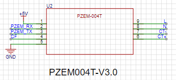
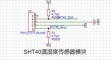
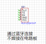
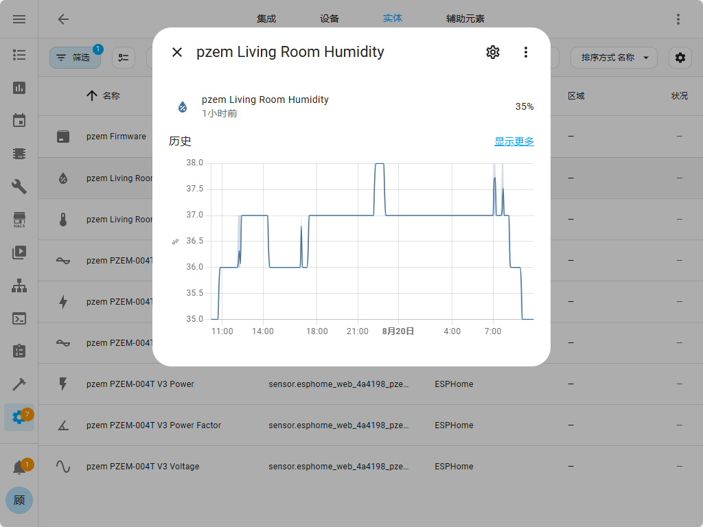
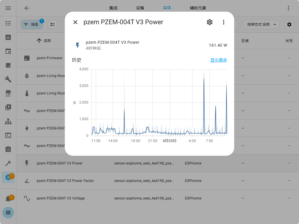
The project plans to use ESP32 modules to reduce soldering burden, and Peizheng PZEM-004T V3 modules to monitor power consumption (current, voltage, power consumption, power factor, apparent power, frequency, etc.) for daily, monthly, and yearly power consumption statistics. A Sensory SHT40 temperature and humidity module (leftover from a temperature and humidity training camp) will be used to monitor temperature and humidity, as the pins would otherwise be wasted. The ESP32's Bluetooth function will also be used as a Bluetooth gateway for Home Assistant, connecting a HI-LINK LD2410 to Home Assistant to enable lights to turn on when someone is present and turn off when they leave (unlike infrared sensors, this only detects presence). A natural gas module was initially planned, but it was decided that since the electrical box and kitchen are not located together, it should be practical rather than added just for the sake of adding it.
A 220VAC to 5VDC module (which I already have, no need to purchase a new one)

and a Peizheng PZEM004T-V3.0 module will be used. This module can monitor AC power, including voltage, current, power factor, and power consumption. Daily, month, and year power consumption can be recorded via software.
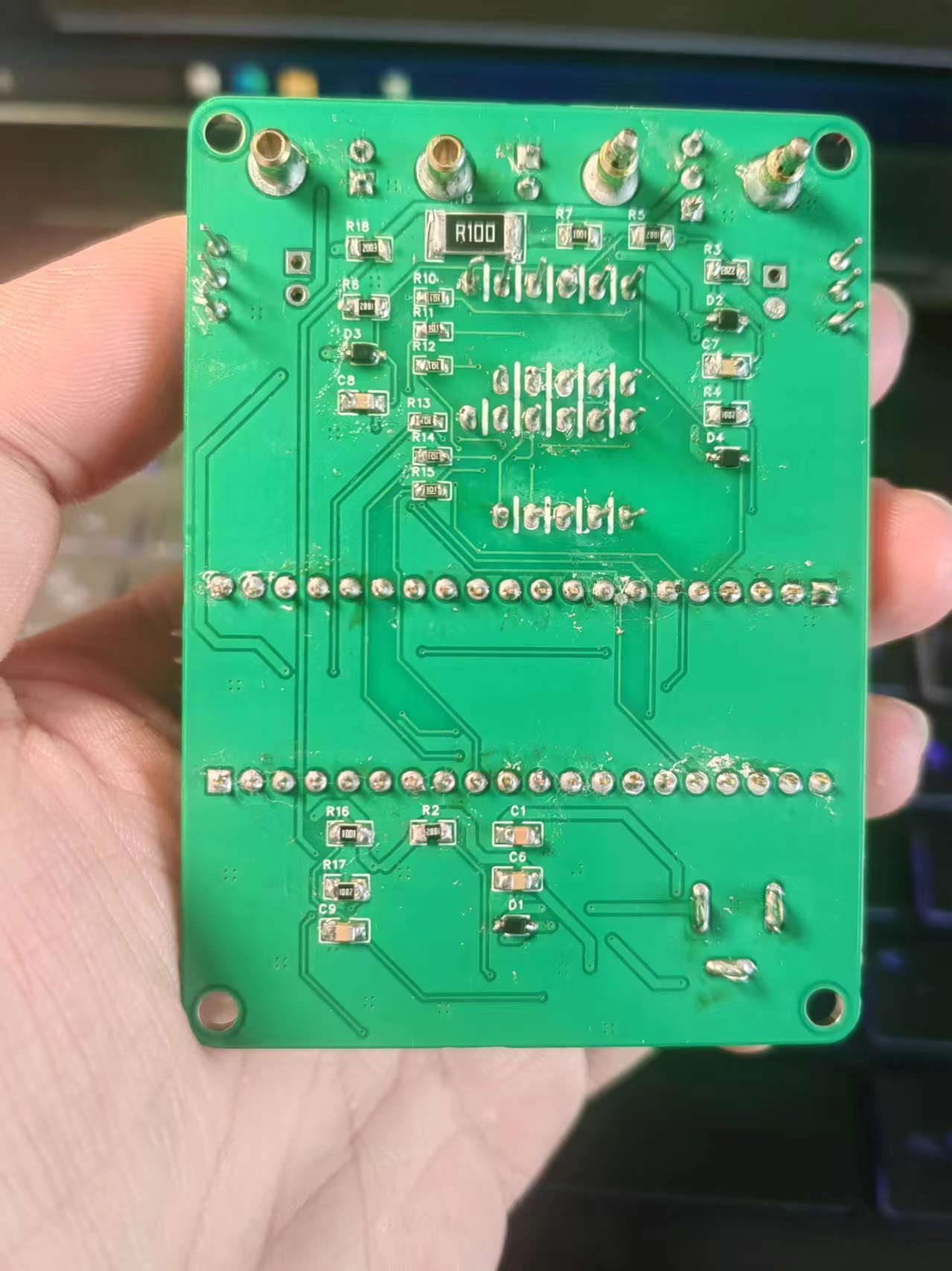
I also have this. I previously built one similar to this project using an ESP-01S. I'll
post a picture
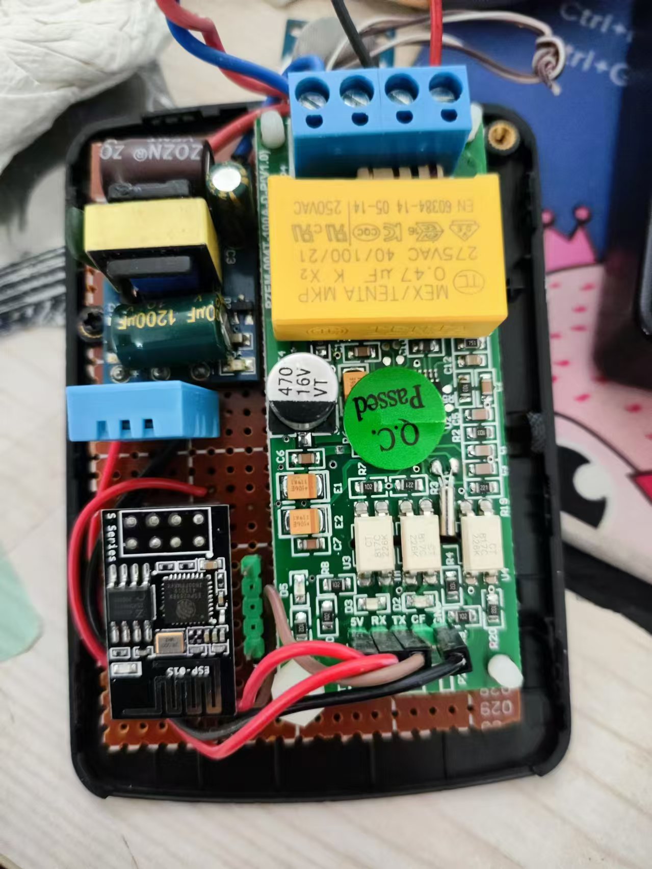
. The Sensirui temperature and humidity module was leftover from a temperature and humidity training camp; I won't say much, just add it.
I also have a HI-LINK LD2410 human presence sensor, which is quite different from a typical human presence sensor. I bought it as a hobby, and I've included that too. It connects via Bluetooth, so this part doesn't require circuitry; just supply it with 5V where it's used.
The buzzer is passive and can actually play music. Active buzzers can't play music.

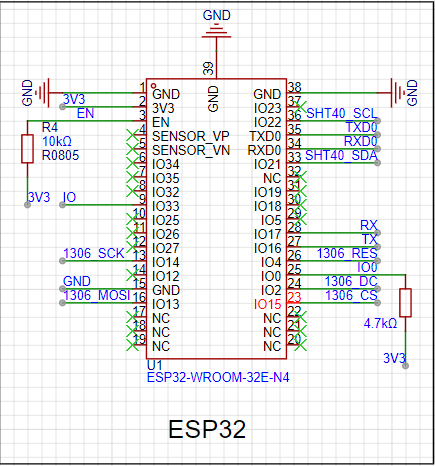
The main controller is a simple ESP32; I couldn't use anything else, so I chose a module for easier soldering. Using a chip would result in a QFN package, which most people probably can't solder.
EN and GPIO0 are absolutely essential! Absolutely essential! Absolutely essential! Pull-up switches are necessary for the module to start properly; don't forget them.
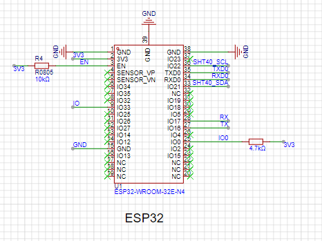
Don't forget the EN and GPIO0 buttons. You need to press the GPIO0 button during programming, and the EN button restarts the module.
It's convenient for programming, but after using esphome for online upgrades, it's basically unnecessary. The 3D casing doesn't have button windows anymore.

Originally, it was designed with a screen, but later I felt it was hidden in the electrical box and wasted power, so I removed it. However, I'm posting the wiring diagram here for my own record and to help those who don't know how. You can use it with confidence; it's been tested and works without problems. It's
the 1306 series, using SPI communication, but I2C can also be used.
The key is to select the correct pins for SCK, MOSI, and CS; for the rest, just choose any usable GPIO.
Of course, you can change the pins on the ESP32 for pin mapping, but it's slow and not beginner-friendly, so let's stick to the standard usage.
The 3D casing isn't particularly designed; it just needs to fit inside. Putting it inside the electrical box is like putting a beautifully designed 3D casing inside a colored screen—it's all for naught.

The programming is even simpler; esphome solves everything. Beginner-friendly!!!
It does feel a bit like a Frankenstein's monster, mainly because it uses what I already have, but it's still very practical. It allows you to track your household's electricity usage, and the charts in Home Assistant are very intuitive. For
those who don't have an AC-to-DC module, you can find other AC-to-DC modules designed by other developers on the LCSC Open Source Platform. I have several, so I'm just posting the modules here; they're not expensive, much cheaper than building one myself.
Also, Home Assistant is really great. You can click on a user-defined image to turn on lights. It can control the air conditioner (though I usually ask Xiao Ai to turn it on...).
Through settings, Xiao Ai can also report voltage, current, and other sensor values designed for this project.
Below is a demonstration of the data obtained from Home Assistant for this project, mainly voltage, current, temperature, humidity, and a specific area. The charts include

humidity,
temperature, current

,

energy consumption,

frequency ,

current power consumption, and
power factor (which reminds me of those fraudulent "energy-saving devices"—the better ones use capacitors to compensate for some power factor, the worse ones just use an LED, hahaha, I wonder if LCSC Open Source Plaza has any energy-saving devices, hahaha, I really want to laugh... Residential electricity doesn't need power factor compensation, but factories and other commercial users do).

The voltage chart is also included

. Most importantly, it automatically calculates electricity consumption by date and time, down to the hour.

You can find tutorials online on how to set these up. If you really can't figure it out, leave a message and I'll tell you.
The YAML file is in the attachment's pasting section.
Paste Transfer.txt
dd.mp4
PDF_esp32 pzem004 Power Monitoring Temperature and Humidity Sensors.zip
Altium_esp32 pzem004 Power Monitoring Temperature, Humidity, and Human Sensing Sensor.zip
PADS_esp32 pzem004 Power Monitoring Temperature, Humidity, and Human Sensing Sensor.zip
BOM_esp32 pzem004 Power Monitoring Temperature, Humidity, and Human Sensing Sensor.xlsx
92790
electronic


 京公网安备 11010802033920号

 NX8567SA509-CC


