
 The current flow
  The voltage calibration circuit uses the TL431, a somewhat old chip
 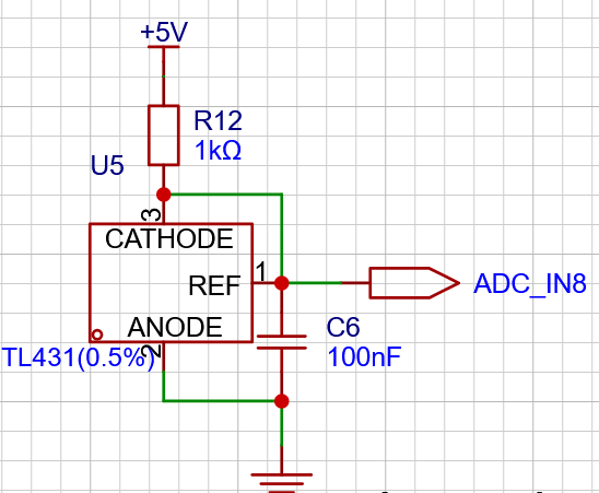 from Youtai Semiconductor, which has a maximum output voltage of 36V.
  Applications and testing circuits are discussed. For further information on other uses of this chip
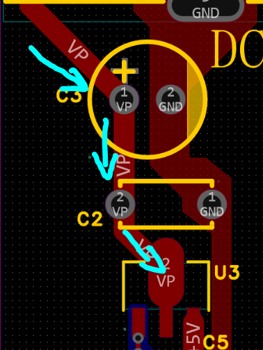
  , please refer to the chip datasheet. The current sampling circuit doesn't have many key points; the main thing to note is the PCB layout
 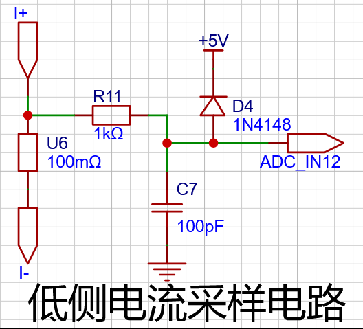 . The sampling resistor traces use a Kelvin connection.
  In power electronics applications, the Kelvin connection also has its applications. For example, in high-precision current measurement, when using a shunt (a small resistor) for current measurement, PCB routing and soldering can affect the current measurement. To solve this problem, a Kelvin connection can be implemented through PCB routing, or a shunt with four terminals can be used to implement a Kelvin connection internally within the device to improve measurement accuracy.
All reference designs on this site are sourced from major semiconductor manufacturers or collected online for learning and research. The copyright belongs to the semiconductor manufacturer or the original author. If you believe that the reference design of this site infringes upon your relevant rights and interests, please send us a rights notice. As a neutral platform service provider, we will take measures to delete the relevant content in accordance with relevant laws after receiving the relevant notice from the rights holder. Please send relevant notifications to email: bbs_service@eeworld.com.cn.
It is your responsibility to test the circuit yourself and determine its suitability for you. EEWorld will not be liable for direct, indirect, special, incidental, consequential or punitive damages arising from any cause or anything connected to any reference design used.
Supported by EEWorld Datasheet
EEWorld
subscription
account

EEWorld
service
account

Automotive
development
community

Robot
development
community

About Us Customer Service Contact Information Datasheet Sitemap LatestNews


Room 1530, 15th Floor, Building B,
No.18 Zhongguancun Street,
Haidian District,
Beijing, Postal Code: 100190
China
Telephone: 008610 8235 0740
 京公网安备 11010802033920号

 XCS20-4VQ256I


