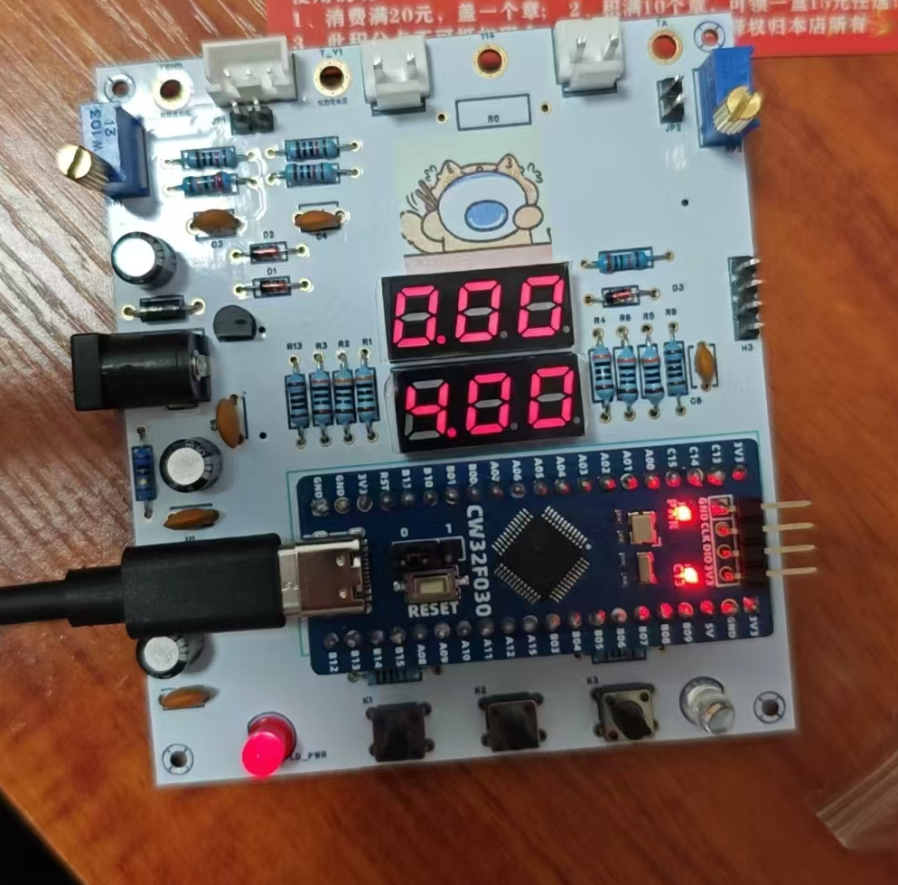
It supports detecting voltage inputs of 0~30V (display accuracy 0.01V) and current inputs of 0~3A (display accuracy 0.01A)
, and supports simultaneous display of voltage and current.
(Due to my limited experience in hardware design, the circuit design follows the official documentation.)
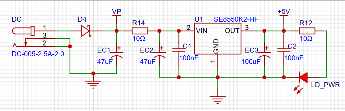
A relatively stable 5V voltage is provided to the circuit through an SE8552K2-HF, and a series diode is used for reverse connection protection.
The reference voltage used in this project is 1.5V, so it is not difficult to calculate from the circuit that the voltage range of this project is 0~30V and 0~5V.
Data is read through an ADC, and then the voltage of the voltage divider resistor is calculated by comparing it with the reference voltage. The measured voltage is then calculated from the resistance relationship between the two resistors. Current sampling
Similar to voltage sampling, an ADC is used to sample the voltage. The obtained value is compared with the 1.5V reference voltage to obtain the voltage of R0, and thus the current in the circuit is calculated.
When calibrating the voltmeter and ammeter, simply insert the jumper cap into JP1 or JP2, and change the resistance by rotating the potentiometer to change the input voltage or current. Then, connect an external multimeter to calibrate the sampling circuit.
: The software development for this project is mainly based on the example programs from Experiment 9 of the training camp. Originally, I designed my own solution, but encountered some difficulties with voltage and current calibration, so the official example programs are provided directly in the attachment.
Function Description:
Voltage measurement ranges are 0-30V and 0-3V; current measurement range is 0-3A.
LED1 on the digital tube displays the voltage, and LED2 displays the current.
Analog voltage measurement corresponds to pin H2, and analog current measurement corresponds to pin H3. Jumper caps are required during use. No current sampling resistor needs to be soldered before using analog current measurement.
An external circuit provides a 2.5V reference voltage.
A 2mm banana plug is used for insertion into the multimeter for measurement.
Hardware Circuit:
DC Power Input:

To avoid introducing DC-DC ripple interference and reduce project costs due to the high voltage difference, this replication project uses an LDO as the power supply, specifically the SE8550K2-HF. Due to my oversight, the actual power supply used was the SE8533K2-HF, the difference being that the output voltage changes from 5V to 3.3V. Initial assessment suggests this will not significantly affect subsequent circuitry. Compared to the original project, only the current-limiting resistor at the TL431 reference voltage needs to be replaced from 1kΩ to 800Ω.
The SE8533K2-HF has a maximum input voltage of 40V and an output of 3.3V with an accuracy of ±2%. The series diodes are used to prevent reverse connection and protect the circuit. Schottky diodes are used to further reduce the voltage drop to approximately 0.2V. The 10-ohm series resistor is used for voltage division, reducing heat generation caused by the high voltage difference across the LDO. It also functions as a low-resistance fuse due to its small overcurrent.
Reference voltage circuit:

In this project, a TL431 is chosen to provide a 2.5V reference voltage to the CW32 ADC. Since the CW32 has built-in 1.5V and 2.5V reference voltages that can be configured in the program, the main purpose of this circuit design is to learn the relevant principles.
The TL431 output voltage is 2.5V with an accuracy of ±0.5%, and its sink current capability is 1mA~100mA (related to the resistor selection in the circuit, as shown in the figure below). More information can be found in TI's TL431 Chinese datasheet.


Since the LDO provides a voltage of 3.3V in this project, based on the above calculation, resistors with an Ω or lower and a package size greater than 0.08W should be selected.
MCU Circuit:
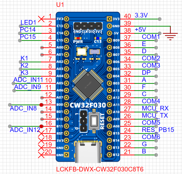
In this project, the CW32F030C8T6 has a wide operating voltage range of 1.65V~5.5V, a 12-bit successive approximation ADC, and four reference voltage sources (VDDA power supply voltage, PB0 pin voltage, built-in 1.5V reference voltage, and built-in 2.5V reference voltage). The voltage
sampling circuit
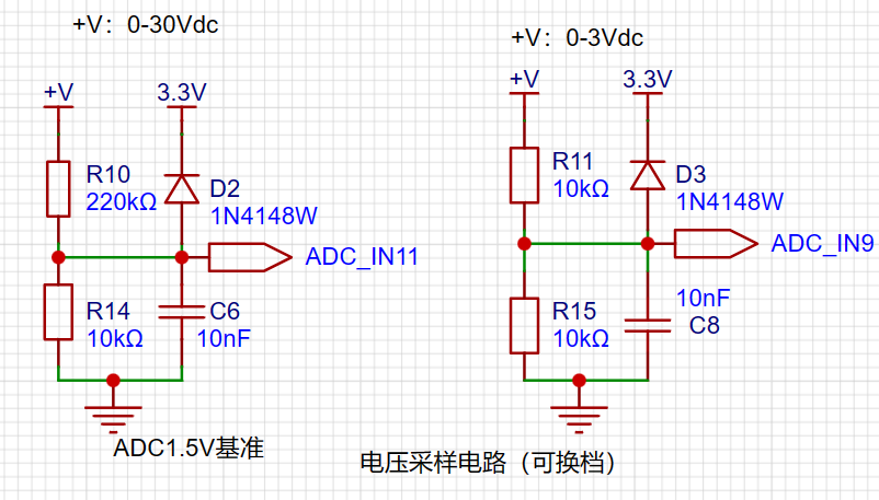
is shown in the figure. The voltage measurement circuit has two ranges to choose from. During measurement, according to the program settings, the more suitable measurement result is selected to improve the measurement accuracy. When the ADC internal reference voltage is selected as 1.5V, the maximum measurement voltage at the high range is calculated based on the voltage divider resistors, and the maximum measurement voltage at the low range is 3V.
The clamping diode limits the ADC pin input voltage to 3.3V. The ADC internal reference voltage can be selected as 1.5V or 2.5V as needed. Since the ADC is 12-bit, selecting the 2.5V range will reduce the measurement accuracy.
Wiring Port Circuit:
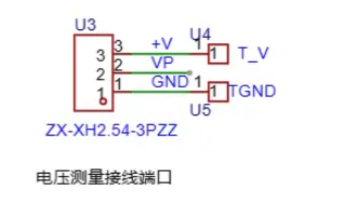
In the figure, U4, U5, U8, and U9 correspond to the 2mm banana plug interface on the PCB, used to insert multimeter probes for easy verification of measurement accuracy and calibration. U3, CN1, and CN2 are the corresponding connection ports for the measured values. +V connects to the voltage to be measured, T_V connects to the red probe of the multimeter, and TGND connects to the black probe. CN2 is connected to the current to be measured; the current flows in from I+ and out from I- on CN2. The red probe of the multimeter is inserted into TI+, and the black probe is inserted into TGND .
Analog voltage measurement:
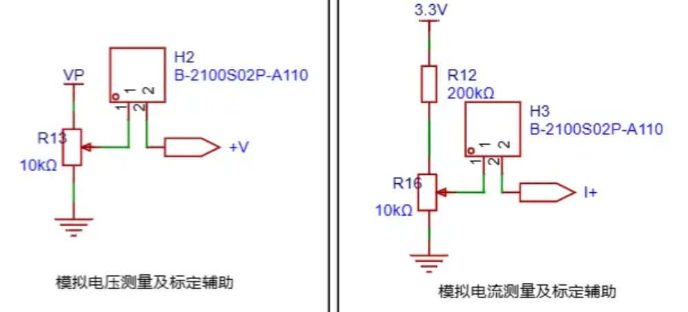
An analog voltage is obtained through an adjustable potentiometer for measuring ADC accuracy and for calibration. A jumper cap needs to be connected during use. When using analog current measurement, the 100mΩ sampling resistor cannot be soldered
. Note:
VP is the provided analog voltage used for calibration;
V+ is the connected measurement voltage.
When there is no DC power supply, the 3.3V on pin header H1 can be used to power the microcontroller.
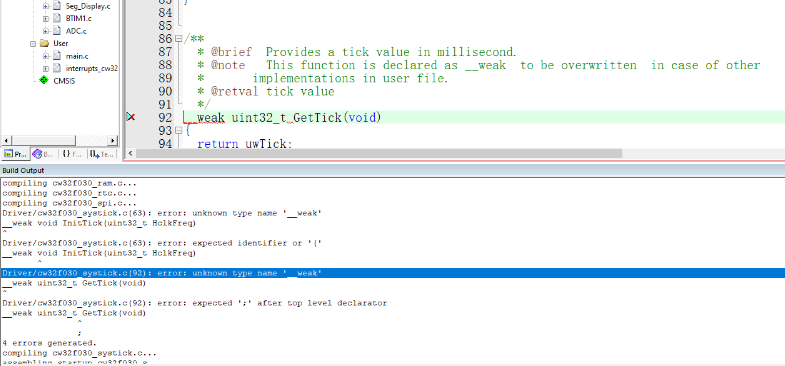
Software part: The firmware package and compiler version selected
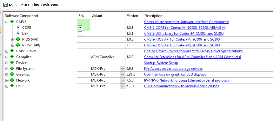
for this project may encounter errors during compilation. Removing __weak will stop the errors. Due to the lack of a DC power line and the fact that the PCB was not traced from the 3.3V power supply, the voltage measurement cannot be verified at this time.

I. Design Background
An ADC (Analog-to-Digital Converter) is an indispensable key component in electronic systems. It converts continuous analog signals into digital signals, enabling digital processing and analysis. ADCs play a crucial role in signal conversion, measurement and data acquisition, control system input, and communication and signal processing. Their widespread application promotes the intelligent and precise control of electronic equipment across various industries, and is one of the key factors driving modern technological progress. Digital voltmeters and ammeters combine ADC technology with circuit measurement principles, accurately converting analog voltage and current signals into digital displays for easy reading and analysis by electronic engineers. This device not only improves the accuracy and efficiency of circuit measurements but also helps engineers better understand circuit behavior, serving as a powerful assistant in electronic design and troubleshooting, and playing a vital supporting role in the work of electronic engineers. In product applications, digital voltmeters ensure the accuracy and safety of circuit design, while also providing strong support for product quality control and subsequent maintenance. Learning to design and build a digital voltmeter and ammeter
using a benchtop digital multimeter (Agilent 34401A)
is highly beneficial for improving one's professional skills. This digital voltmeter and ammeter project covers multiple aspects, including microcontroller circuit design and implementation, signal acquisition and processing circuit design, user interface development and optimization, and product appearance design. It integrates knowledge from multiple fields such as electronics, microcontroller programming, circuit design, and industrial design. Considering the learning pace and knowledge absorption capacity of beginners, we have specially launched this introductory-level digital voltmeter and ammeter project, which is very suitable for beginners in electronics and those who want to learn more about microcontroller applications. This project has the following highlights:
it adopts a core board plus expansion board design concept and uses plug-in components, making learning simpler and exploration more in-depth;
the core board uses the domestic Wuhan Xinyuan Semiconductor CW32 as the main controller, while also being compatible with other similar development boards; however, the CW32 has advantages.
The project is highly comprehensive and practical, and after completion, it can be used as a desktop instrument;
the project has abundant learning materials, including circuit design tutorials, PCB design, code programming learning, and training for engineers' debugging skills.
II. Hardware Design
1. Power Supply Circuit

LDO (Low Dropout Linear Regulator) Selection This project uses an LDO as the power supply. Considering that most voltmeter products are used in industrial scenarios with 24V or 36V power supplies, the SE8550K2 with a maximum input voltage of up to 40V was selected as the power supply. The main reason for not using a DC-DC step-down circuit to handle the large voltage drop is to avoid introducing DC-DC ripple interference during the design process, and the secondary reason is to reduce project costs.
2. MCU Selection Analysis
To reduce the learning cost for everyone, this project uses the LCSC CW32F030C8Tx development board (core board) as the main controller, but this does not mean that we will talk less about this section. From the perspective of training engineers, the correct selection of the main controller is very important, as it relates to the overall advantage of the project. Regarding the voltmeter and current meter, the author used STM32/CW32 and some other 32-bit microcontrollers for some debugging and testing. This comparison is only with the STM32F103C8T6 as a reference for device selection, primarily aimed at providing ideas and improving understanding.
Avoid blind selection. When selecting an MCU (Microcontroller Unit) for this project, multiple aspects need to be considered to ensure the chosen MCU meets project requirements.
Clearly define your project needs: Understand the required computing power, including clock speed, processor core type, and whether a floating-point unit is needed.
Identify the required I/O ports and important peripherals, such as ADC peripherals. Since this is a development board project, primarily for debugging and learning, there are no strict limitations on the number of I/O ports: i.e., the associated costs are not considered.
Key advantages of the CW32 in this project
: Wide operating temperature range: -40~105℃;
Wide operating voltage range: 1.65V~5.5V (STM32 only supports 3.3V systems)
; Superior interference immunity: HBM ESD 8KV; All ESD reliability meets the highest international standard (STM32 ESD 2KV)
; Project focus - Better ADC: 12-bit high-speed ADC, achieving ±1.0LSB INL 11.3ENOB; Multiple Vref reference voltages... (STM32 only supports VDD=Vref);
Stable and reliable eFLASH technology.
A detailed explanation of these advantages will be provided in the chapters on ADC sampling and related extensions.
The main characteristics of the CW32 ADC: This project requires a focus on the 4 reference voltage sources. (Content from the "CW32x030 User Manual")

3. Voltage Sampling Circuit:
The voltage divider resistors in this project are designed to be 220K+10K, therefore the voltage division ratio is 22:1 (ADC_IN11).
The voltage divider resistor selection
is designed to measure the maximum voltage. For safety reasons, this project uses 30V (the actual maximum display value can be 99.9V or 100V).
The ADC reference voltage is 1.5V in this project, and this reference voltage can be configured through the program.
To reduce the power consumption of the sampling circuit, the low-side resistor (R7) is usually chosen as 10K based on experience.
Then, the high-side resistance of the voltage divider resistor can be calculated using the above parameters.
The required voltage division ratio is calculated, i.e., the ADC reference voltage. The input voltage is designed; using known parameters, 1.5V/30V = 0.05 can be calculated.
The high-side resistance is calculated as the low-side resistance/voltage division ratio; using known parameters, 10K/0.05 = 200K can be calculated.
A standard resistor is selected: a resistor slightly higher than the calculated value of 200K is chosen. We usually choose E24 series resistors; therefore, in this project, 220K, which is greater than 200K and closest to the calculated value, is selected.
If, in actual use, the voltage to be measured is lower than 2/3 of the module's design voltage (66V), the voltage divider resistor can be replaced and the program modified to improve measurement accuracy. The following example illustrates this:
Assuming the measured voltage is no higher than 24V and other parameters remain unchanged,
calculations show 1.5V/24V = 0.0625, 10K/0.0625 = 160K. 160K is a standard E24 resistor and can be directly selected, or a higher value 180K can be chosen with some redundancy.
If, in actual use, the voltage to be measured is higher than the module's 99V design voltage, a different resistor can be selected. To expand the voltage measurement range, you can choose to replace the voltage divider resistor or modify the reference voltage. The following example illustrates this:
Assuming the measured voltage is 160V, we can choose to increase the voltage reference to expand the range.
Given that the voltage division ratio of the selected resistor is 0.0145, we can calculate 160V * 0.0145 = 2.32V using the formula. Therefore, we can choose a 2.5V voltage reference to expand the range (increasing the range will reduce accuracy).
Considering the potential fluctuations in the measured power supply, a 10nF filter capacitor is connected in parallel with the low-side voltage divider resistor in the circuit design to improve measurement stability.
(Range switching )
In this project, an additional voltage sampling circuit was added. Therefore, we can discuss the significance of range switching for improving measurement accuracy. Multimeters often have multiple range settings to achieve more accurate measurements. By adjusting different ranges, the optimal measurement accuracy of the measured point within the corresponding range can be obtained.
This project requires a combination of hardware and software to implement this function. When we first use the ADC_IN11 channel mentioned earlier to measure voltages below 30V, if the measured voltage is within 0~3V, then we use the ADC_IN9 channel for measurement. At this time, due to the reduced voltage division ratio, the measurement accuracy is greatly improved. There are many ways to implement range switching; the development board design provides more design possibilities.
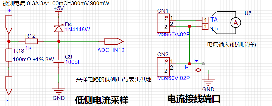
4. Current Sampling Circuit
This project uses a low-side current sampling circuit for current detection. When learning the common ground between the low-side of the sampling circuit and the development board's meter interface, please do not solder R0!!!
The design analysis
for this project involves a sampling current of 3A, and the selected sampling resistor (R0) is 100mΩ. The selection of the sampling resistor mainly needs to consider the following aspects:
the maximum value of the pre-designed measurement current;
the voltage difference caused by the 3A current sensing resistor in this project; and
the power dissipation of the current sensing resistor, which should generally not exceed 0.5V. A suitable package should be selected based on this parameter. Considering the power dissipation (temperature) issue under high current, a 1W metal wire-wound resistor package was chosen
. The voltage amplification factor across the current sensing resistor is also important. Since no operational amplifier is used to build the amplification circuit in this project, the factor is 1.
The current sensing resistor value can then be calculated using the above parameters
. Since no amplifier circuit is used, a larger sampling resistor is needed to obtain a higher measured voltage for measurement.
Considering that a larger resistor would result in a larger voltage drop and higher power consumption, an unlimited selection of a larger resistor is not feasible.
This project uses a 1W package resistor, corresponding to a power consumption of 1W.
Based on the above data, a 100mΩ current sensing resistor was selected. According to the formula, 3A * 100mΩ = 300mV, 900mW can be calculated.
To cope with different operating environments, especially high-current scenarios, the R0 resistor can be replaced with constantan wire or a shunt. The replacement can be selected according to the actual application scenario. For safety and educational purposes, this project will not discuss measurements exceeding 3A in detail, but the principle is the same.
5. Digital Tube Display
This project uses a digital tube as the display unit.
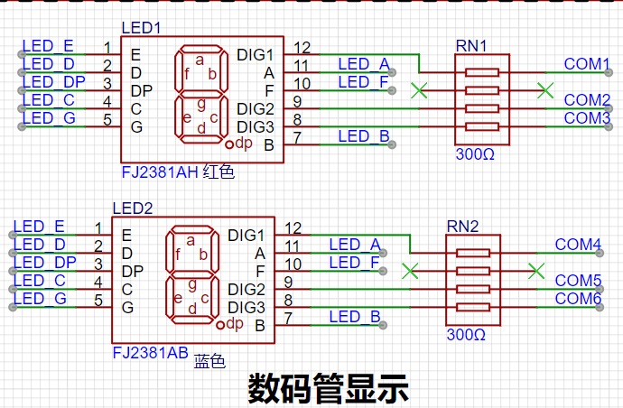
This project uses two 0.28-inch three-digit common-cathode LED displays as display devices. Compared to displays, LED displays offer better visibility in complex environments. The brightness of the LED displays can be increased by using smaller current-limiting resistors to meet the needs of the actual usage environment. Furthermore, LED displays have better mechanical properties and are not as easily damaged by external forces as displays. They are widely used in industrial applications requiring stability and reliability. From a development board learning perspective, this facilitates targeted learning of electronic measurement principles.
In this project, actual testing showed that a 300Ω current-limiting resistor for the LED displays resulted in good visibility for both red and blue LED displays, with a soft and non-glaring brightness.
6. TL431 Circuit Design for Voltage Measurement Calibration:
This project adds an additional TL431 circuit to provide a 2.5V reference voltage. This can be used to provide an external voltage reference for calibrating the AD converter. From a product design perspective, due to the inherent ADC performance advantages of the CW32, this circuit is not necessary. This circuit was designed on the development board to learn relevant application principles.

The TL431 is a relatively "old" device, a classic with wide applications, and still found in many electronic products.
Many beginners may be encountering this device for the first time, so we'll briefly explain its principles to help you better utilize the TL431.
TI defines it as a "Precision Programmable Reference," and we can focus on several key characteristics on the first page of the references.
Precision: Precision indicates its highly accurate output voltage. The TL431 I used has ±0.5% accuracy, and at room temperature, it measured 2.495V on the board. Compared to common Zener diodes, the accuracy is vastly different. In application circuit diagrams, the TL431 is internally represented by a Zener diode symbol.
Adjustable Output Voltage: The adjustable output voltage is between Vref and 36V. In our project, we use the output Vref voltage, which is approximately 2.5V. Therefore, we use 2.5V in the description, which is approximately equal to Vref.
Sinking Current Capability: This refers to how much current the output voltage pin can provide, which is greatly affected by the resistance value (R13) in the application circuit. The current should not be lower than 1mA. If there is no need for sinking current, do not design the current to be too high, as this will cause unnecessary power consumption.
7. Demonstration
Altium_Based on the [LCSC GeoStar Development Board] Voltage and Current Meter.zip
BOM_Based on the voltage and current meter of the [LCSC GeoStar Development Board].xlsx
 A relatively stable 5V voltage is provided to the circuit through an SE8552K2-HF, and a series diode is used for reverse connection protection.
  The reference voltage used in this project is 1.5V, so it is not difficult to calculate from the circuit that the voltage range of this project is 0~30V and 0~5V.
 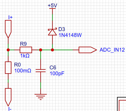 Similar to voltage sampling, an ADC is used to sample the voltage. The obtained value is compared with the 1.5V reference voltage to obtain the voltage of R0, and thus the current in the circuit is calculated.
  When calibrating the voltmeter and ammeter, simply insert the jumper cap into JP1 or JP2, and change the resistance by rotating the potentiometer to change the input voltage or current. Then, connect an external multimeter to calibrate the sampling circuit.
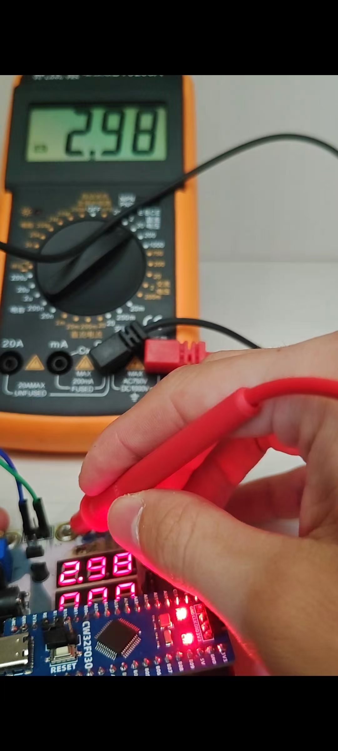


 京公网安备 11010802033920号

 TSIC106WST


