 Schematic:
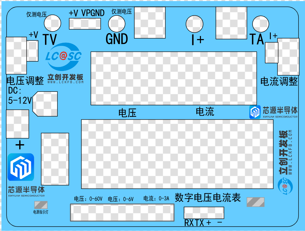
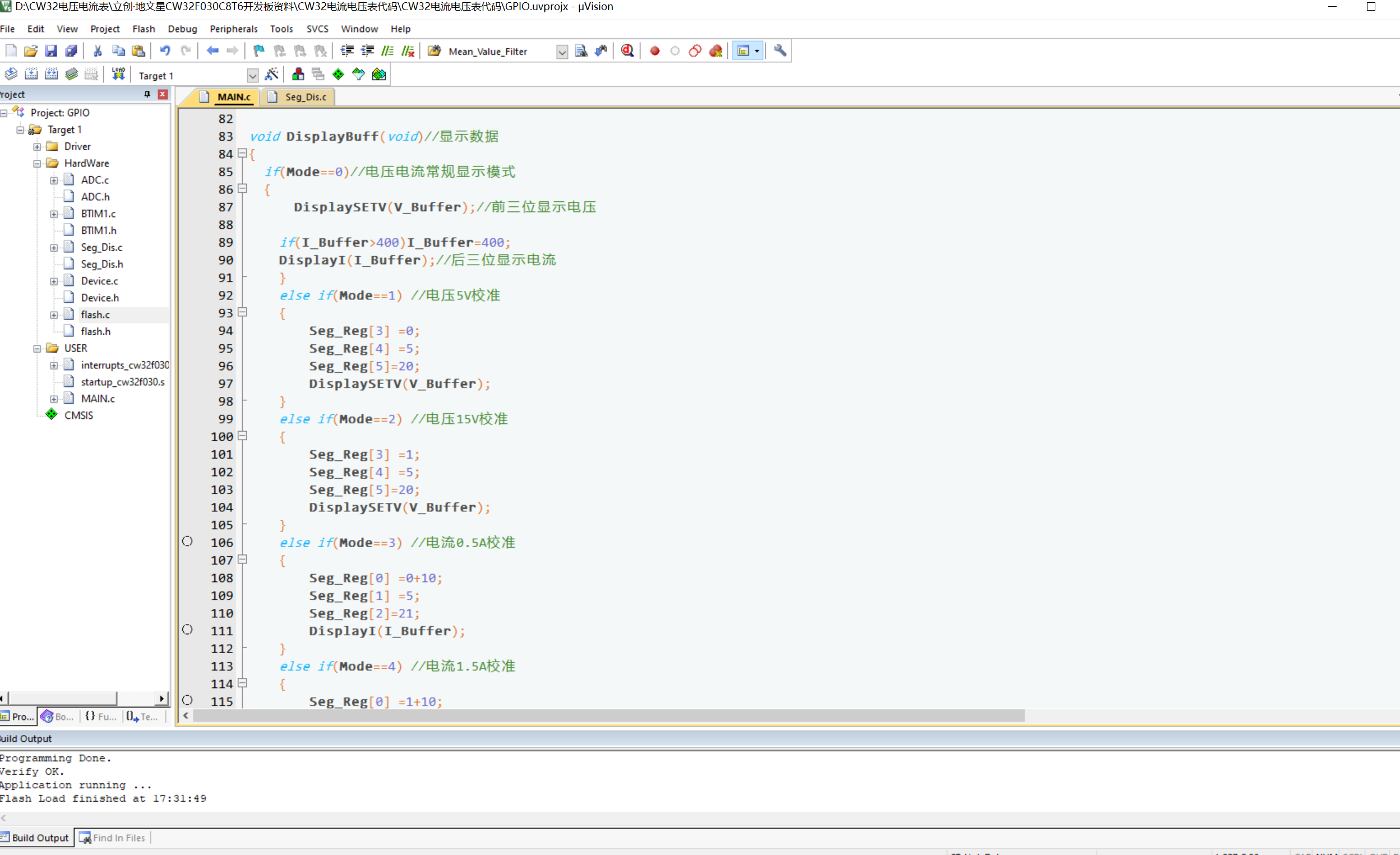
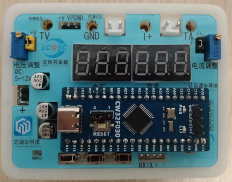
  Schematic: Draw the 3D shell outline in JLCPCB EDA. Then, set the cutout areas according to the locations of the holes. This project selects a top cutout, and another rectangular cutout on the top surface to hold the panel. Place the 3D shell screw posts according to their positions. Select reinforcing ribs on the top surface, not countersunk holes. Install screws from the bottom. Before drawing the 3D shell panel, first export the DXF file, selecting to export the top layer, board frame layer, hole layer, multi-layer pads in the 3D shell layer, board frame, 3D shell border, and the 3D shell top surface cutout area. Then import it into the panel file, set the border as the border layer, and set the area to be cut out as the cutout layer. You can place images, text, and background colors on the printing layer. Place the labeled text. If the background color of the printing layer is not transparent and there are lights to be displayed, set the light position as a transparent control layer. Panel diagram 5. Software part : Use KEIL to write embedded programs. First, turn on the clock and configure the GPIO port initialization. Configure the LED lights, buttons, and digital tubes. Then turn on the timer and ADC analog-to-digital conversion to measure voltage and current values. The buttons are triggered externally using a timer, and the LEDs also use a timer to blink for one second. 6. Physical demonstration part: Physical diagram without 3D shell and panel installed. Physical diagram with 3D shell and panel installed.


All reference designs on this site are sourced from major semiconductor manufacturers or collected online for learning and research. The copyright belongs to the semiconductor manufacturer or the original author. If you believe that the reference design of this site infringes upon your relevant rights and interests, please send us a rights notice. As a neutral platform service provider, we will take measures to delete the relevant content in accordance with relevant laws after receiving the relevant notice from the rights holder. Please send relevant notifications to email: bbs_service@eeworld.com.cn.
It is your responsibility to test the circuit yourself and determine its suitability for you. EEWorld will not be liable for direct, indirect, special, incidental, consequential or punitive damages arising from any cause or anything connected to any reference design used.
Supported by EEWorld Datasheet
EEWorld
subscription
account

EEWorld
service
account

Automotive
development
community

Robot
development
community

About Us Customer Service Contact Information Datasheet Sitemap LatestNews


Room 1530, 15th Floor, Building B,
No.18 Zhongguancun Street,
Haidian District,
Beijing, Postal Code: 100190
China
Telephone: 008610 8235 0740
 京公网安备 11010802033920号

 AS29LV400B-90SI


