
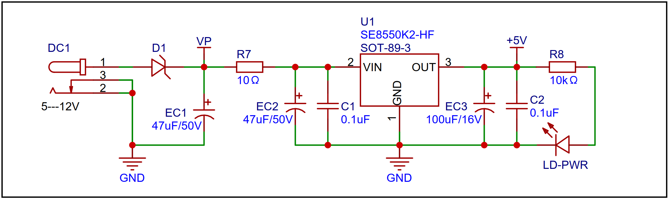
 An LDO is used as the power supply, with an SE8550K2 chip selected. It can handle up to 40V input voltage, meeting 24V and 36V DC power supply scenarios.
 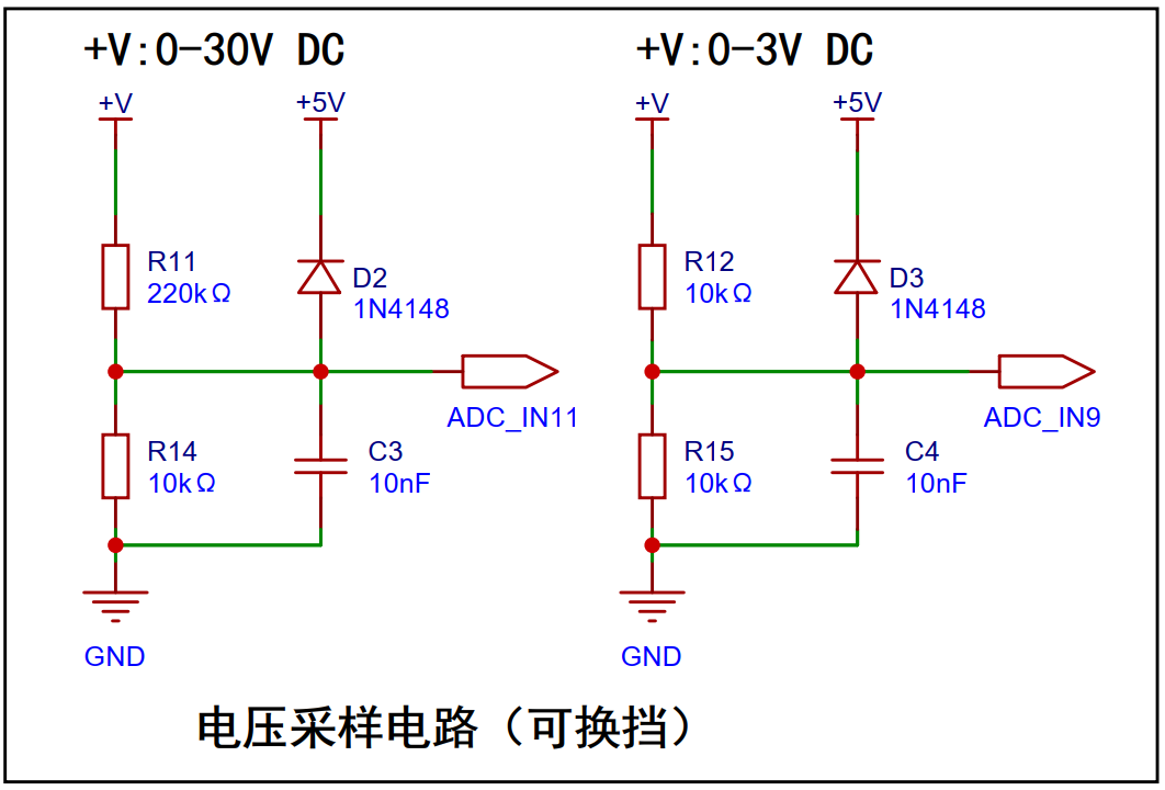 The voltage sampling circuit uses two sampling channels, with different resistors for voltage division, to achieve two measurement levels. With the ADC reference set to 1.5V, the sampling resistor ratio for 0~30V should be 20:1. To reduce power consumption, R14 is chosen as 10K, and a resistor slightly larger than 200K, R11, is chosen as 220K. Of course, the sampling resistor ratio can be changed to expand the measurement range.
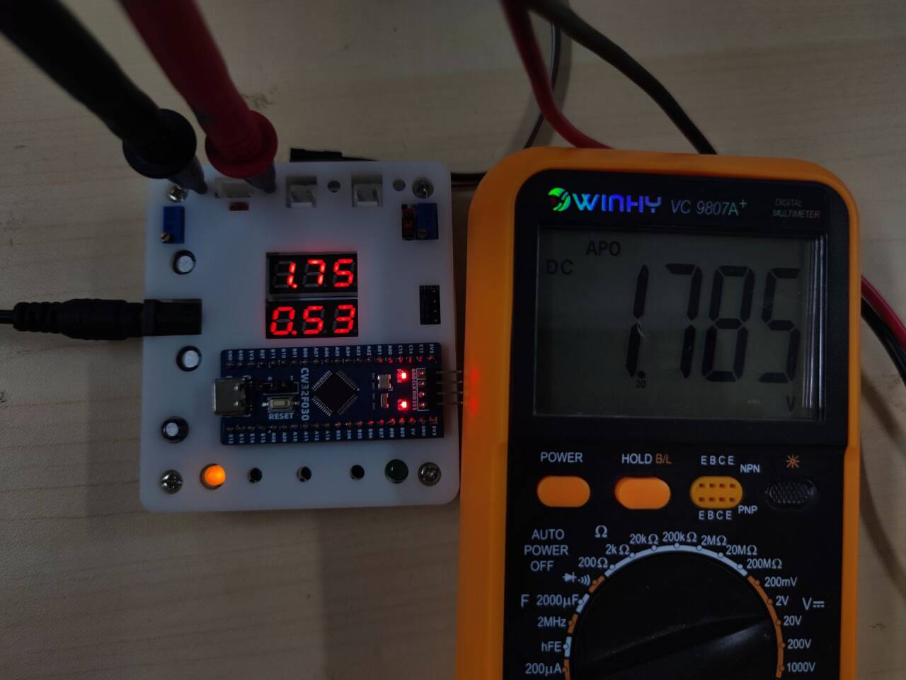
 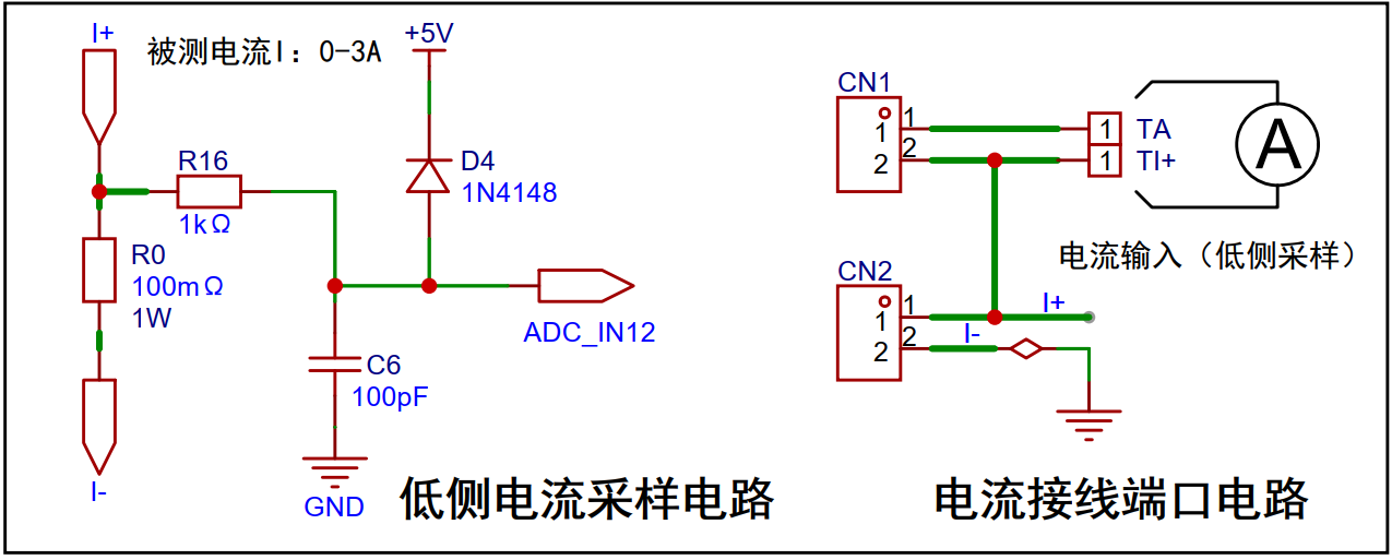 uses a 100mΩ sampling resistor. The principle is that current passing through the resistor generates a voltage drop, and the current magnitude is obtained by sampling the voltage across R0. The accuracy of R0 should be as high as possible, and the resistor's heat generation should be considered; here, a power rating of 1W is chosen.
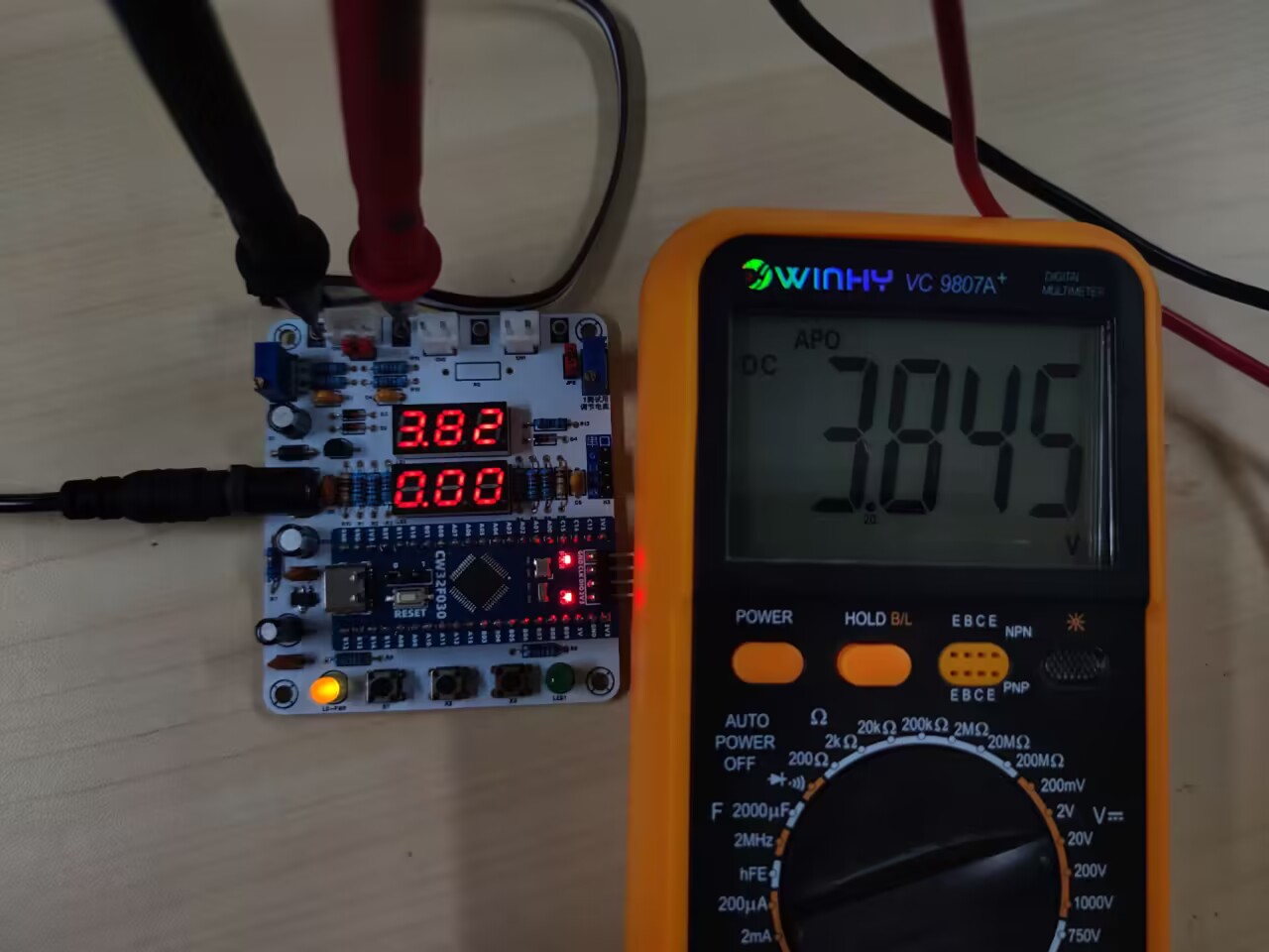
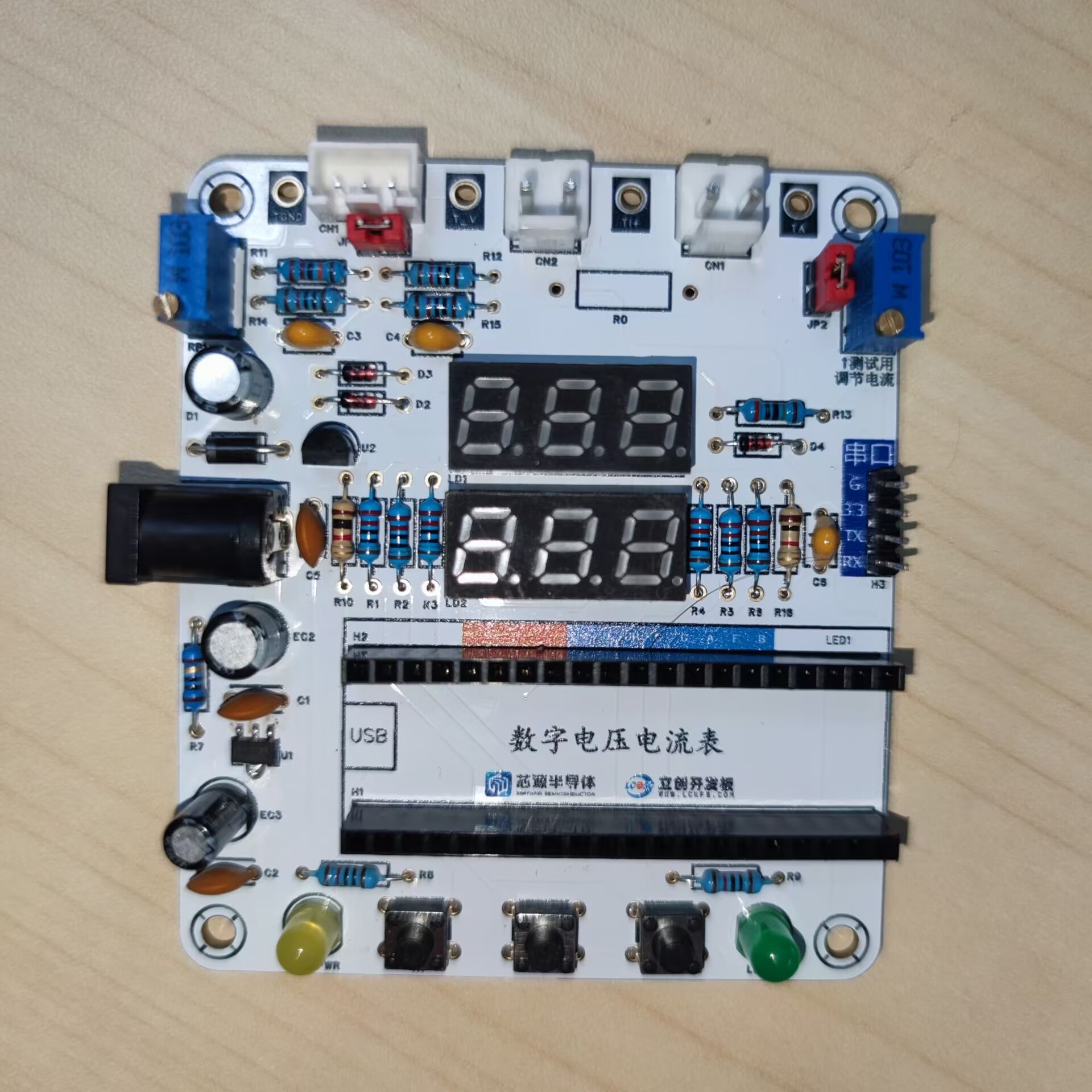
 This is a 3D-printed shell
 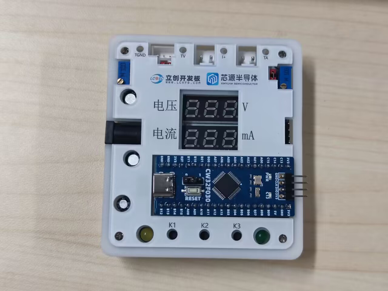 placed on the panel. My buttons are relatively short, so they are not pressable with the shell on.
All reference designs on this site are sourced from major semiconductor manufacturers or collected online for learning and research. The copyright belongs to the semiconductor manufacturer or the original author. If you believe that the reference design of this site infringes upon your relevant rights and interests, please send us a rights notice. As a neutral platform service provider, we will take measures to delete the relevant content in accordance with relevant laws after receiving the relevant notice from the rights holder. Please send relevant notifications to email: bbs_service@eeworld.com.cn.
It is your responsibility to test the circuit yourself and determine its suitability for you. EEWorld will not be liable for direct, indirect, special, incidental, consequential or punitive damages arising from any cause or anything connected to any reference design used.
Supported by EEWorld Datasheet
EEWorld
subscription
account

EEWorld
service
account

Automotive
development
community

Robot
development
community

About Us Customer Service Contact Information Datasheet Sitemap LatestNews


Room 1530, 15th Floor, Building B,
No.18 Zhongguancun Street,
Haidian District,
Beijing, Postal Code: 100190
China
Telephone: 008610 8235 0740
 京公网安备 11010802033920号

 2SC4011TV4/Q


