I. Team Introduction:
Song Yinglu, a model student from the "University of Social Learning" program.
II. Project Requirements:
This project draws inspiration from automation solutions in various industries to design a digital temperature and humidity detector. It utilizes an STM32G030K6T6 microcontroller combined with temperature and humidity sensors to detect and display environmental parameters. The designed system uses the microcontroller as its core for hardware circuit design, mainly including a three-bit output 8-bit shift register circuit, a digital tube display circuit, a power supply circuit, and an LED display circuit. On the software side, the system is programmed in C language under the Keil5 development environment, with a main program and multiple functional subroutines designed according to the system's functions. Finally, the hardware prototype is developed, debugged, and simulated for testing. The experimental results confirm the correctness of the design.
III. Design Abstract:
Temperature and humidity are parameters that must be monitored in industrial production, agricultural cultivation, and daily life. Traditionally, temperature and humidity are detected separately using different devices, which are relatively outdated, lack intuitive display, and are inconvenient to use. In recent years, with the development of microelectronics, computers, automatic control, and sensor technologies, automation technology has been increasingly widely applied in many traditional industries, completely changing traditional production models. More and more engineers and scholars are applying new technologies to systems and have achieved significant detection, analysis, and control effects.
IV. Problem Analysis
The microcontroller-based temperature and humidity measuring instrument is a typical embedded system project, mainly used in environmental monitoring fields such as homes, greenhouses, and laboratories. The core of this project is using a microcontroller for data acquisition, processing, and display to monitor the temperature and humidity of the environment in real time. The key knowledge points involved will be detailed below.
1. Microcontroller Basics
A microcontroller, also known as a microprocessor, is an integrated circuit that integrates components such as CPU, RAM, ROM, and I/O interfaces. It is often used to implement control systems with specific functions. In this project, the microcontroller acts as the core processor, responsible for reading data from the temperature and humidity sensors, processing it, and presenting it through a display device.
2. Temperature and Humidity Sensors
Temperature and humidity measurement in this project typically uses integrated temperature and humidity sensors such as the DHT series or HTU21D. These sensors can simultaneously measure temperature and humidity and interact with the microcontroller through a single bus or I2C communication protocol. The data output by the sensor is parsed by the microcontroller and converted into readable values.
3. Program Source Code The source
code is usually written in C or assembly language to implement the control of the microcontroller. The code mainly includes the implementation of initialization settings, data acquisition, data processing, and communication protocols. This project may contain the following functions or modules:
Initialization: Setting the microcontroller's clock, I/O ports, etc.
Data Acquisition: Calling library functions to read sensor data.
Data Processing: Calculating temperature and humidity values, possibly including calibration and filtering algorithms.
Display Module: Updating the LCD screen or other display devices based on the processing results. Communication Module:
Implementing communication with the host computer or other devices, such as serial communication.
4. Schematic Diagram The schematic
diagram depicts the hardware connections of the system, including the connections between components such as the microcontroller, sensors, power supply, and display devices. The circuit diagram helps in understanding the hardware's working principle and provides a basis for hardware debugging. When designing the circuit, factors such as power management, signal anti-interference, and protection circuits need to be considered.
5. Demonstration Video and Explanation Documentation
The demonstration video can intuitively show the system's operation process and actual effects, while the explanation document provides detailed textual explanations, including project background, system architecture, hardware and software design ideas, implementation steps, debugging methods, etc., helping learners understand and reproduce the project.
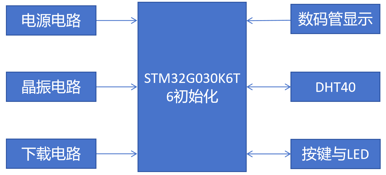
V. Overall Design Block Diagram
The following is the overall design block diagram of the system.
VI. Hardware Circuit Composition
The following is the PCB schematic of the hardware circuit, mainly including the main control circuit, crystal oscillator module, SHT40 temperature and humidity sensor module, three-digit output 8-bit shift register, common cathode 3-digit digital tube, two AA battery boxes + reverse connection protection, test LEDs, and SWD download and debugging circuit.

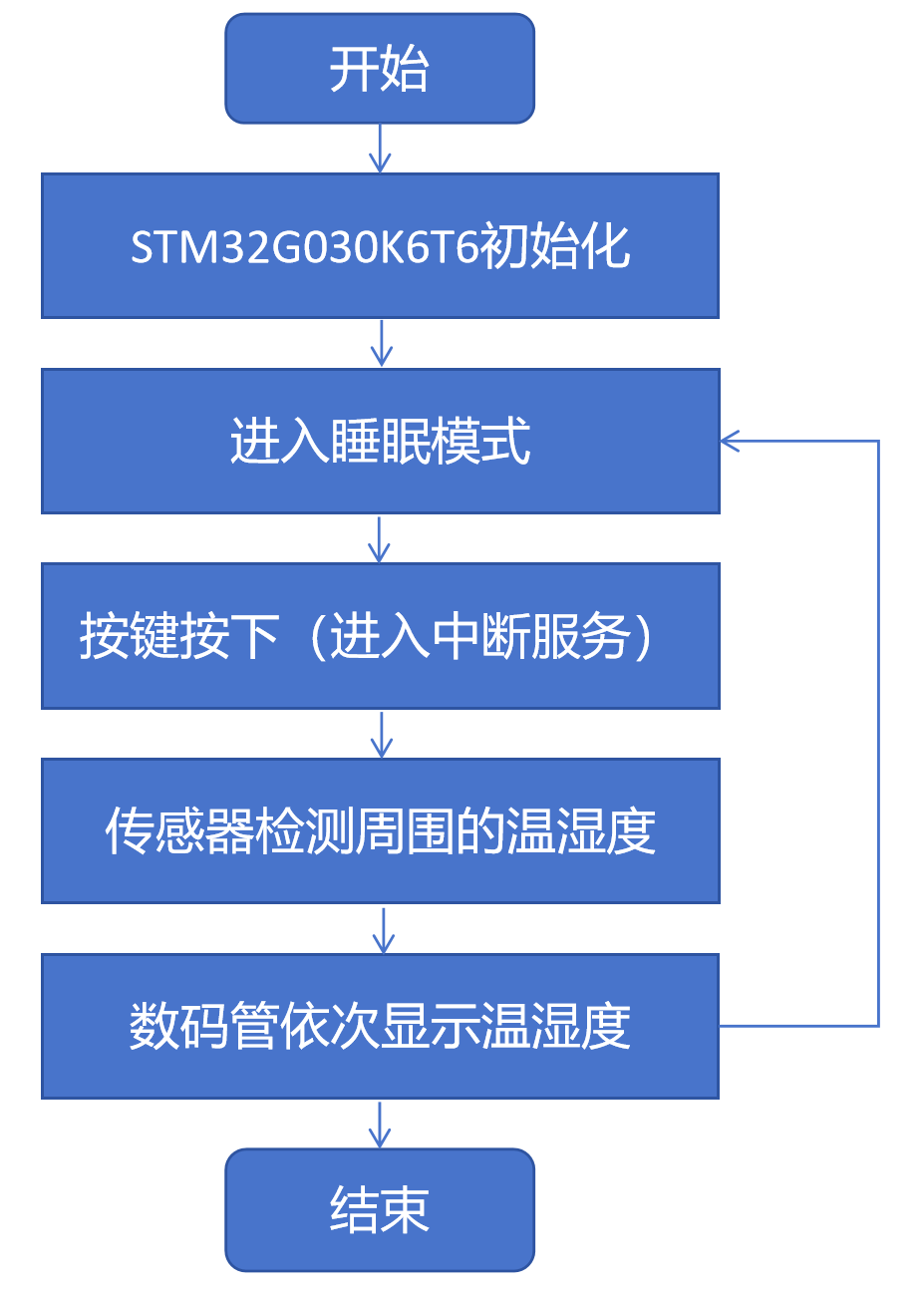
VII. Program Flowchart
The following is the software program flowchart of the system.
VIII. Physical Demonstration

IX. Precautions
Solder from smallest to largest, pay attention to the positive and negative terminals of the LEDs, and select the corresponding download module when downloading the circuit.
X. Attachments Attachment
1: Physical Video Demonstration
Attachment 2: Program Source Code


 京公网安备 11010802033920号

 M55342H04B164AMTS


