flashlight: The old man upstairs thought it was dawn. 200 yuan hand-made 200 watt 27000 lumen flashlight_Bilibili_bilibili
Light Hammer 200 Replica Exchange Group: 522608529 You can ask me questions in there if you encounter any problems during the replica process.
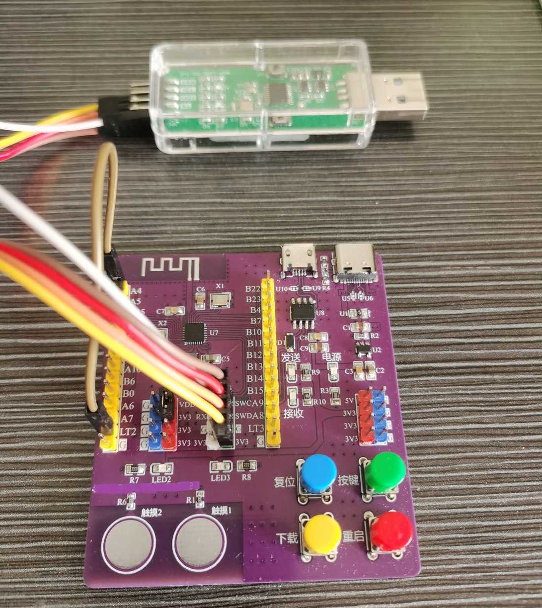
The Qinheng CH592X test board comes with an LDO and a serial-to-USB interface (via CH340N).
I applied
for several CH592X chips and wanted to quickly build a development board to test them out.
Features include
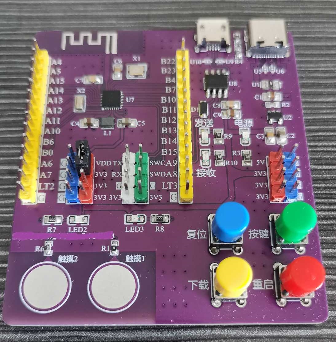
onboard reset, download, restart, and custom buttons. It
has an onboard serial-to-USB interface (CH340N) with LED indicators for easy observation.
Most components use 0805 packages for easy soldering.
It includes two touch pads.
An external WCH-LINK interface is provided and has been successfully tested.
Testing
was limited to the Peripheral and Touch_Key programs in the CH592X example code, both of which passed.
Note:
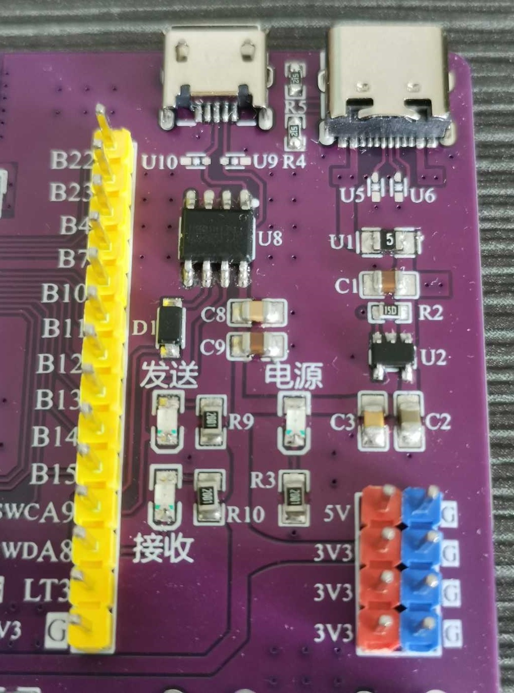
When using, simply insert a jumper between the VDD and 3V3 pin headers (see the image below). These two headers can also be used to test quiescent current (connect the red and black probes of a multimeter to these two headers respectively).
For the first download, use WCHISPStudio (download from the WCH website). Do not press the "Download" button. If WCHISPStudio does not detect the development board, press the "Restart" button to be recognized. After the first successful download, press and hold the "Download" button on the board, then press and release the "Restart" button. WCHISPStudio will then recognize the device.
If you need to use WCH-LINK, remember to enable "Enable Two-Wire Simulation" at the bottom of WCHISPStudio.
Note that
the anti-static diodes are optional. The antenna may cause issues during DRC testing; simply ignore this.


PDF_CH592X test board.zip
Altium_CH592X test board.zip
PADS_CH592X test board.zip
BOM_CH592X Test Board.xlsx
93873
STLINK
General use with Stlinkv2, v2.1, and Daplink
A universal solution for ST-Link v2, v2.1, and DAPLink
has been successfully fabricated and verified.
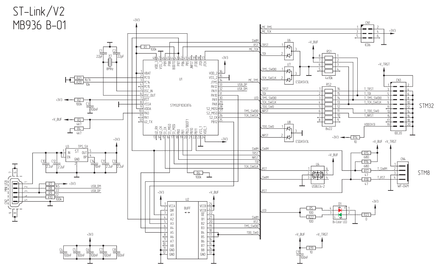
Design based on ST -Link v2 schematics
uses the STM32F103C8T6
. ST-Link v2.1 and DAPLink use the
STM32F103CBT6. DAPLink can also use the APM32F103CBT6 (tested).
DAPLink firmware compilation tutorial:
[DAPLink Firmware Source Code Compilation]
DAPLink source code:
https://github.com/ARMmbed/DAPLink
ST-Link v2 Reverse.pdf
STLinkV2.J16.S4_Firmware.zip
STLinkV2.J28.M18_Firmware.zip
stlink-V2.J21.S4.zip
stm32f103xb_bl.hex
stm32f103xb_stm32f103rb_if.hex
BOM_STLINK.xlsx
93875
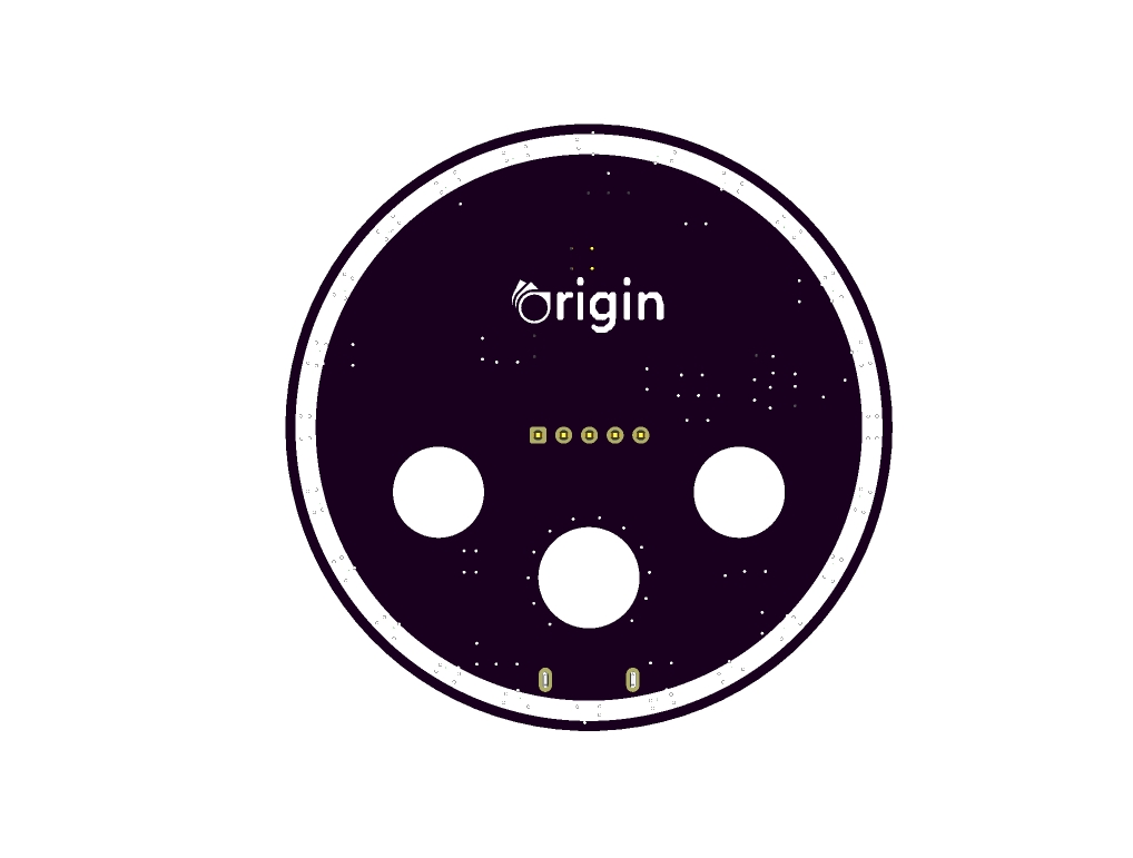
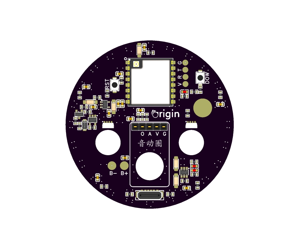
Car Audio Driver - Ornament (for Cars)
This is a random piece that comes from the design. It's a great decorative item to put at home or in the car. It plays music and also monitors noise levels.
Musical rhythm, noise monitoring, triggered at a touch.
A unique electronic ornament: MAX9814+ EPS07. It's not just a decoration for your home, but a rhythm sensor for your life. Through the highly sensitive MAX9814 sound sensor, it can monitor changes in ambient noise in real time, responding to your voice and the rhythm of music. The EPS07 processor transforms this information into dynamic light effects, changing color and brightness with the beat, adding endless fun to your space. Whether placed at home or in your car, this electronic ornament adds a touch of intelligence and art to your life.

Open Source License
This project uses the CC-BY-NC-SA 3.0 open source license, i.e., Creative Commons Attribution-NonCommercial-ShareAlike License.
PCB Preview
Function Description
1. Built-in battery & USB power supply, dual power supply, automatic switching, external power supply prioritized.
2. Linear rainbow multi-color indicator, direction automatically rotates every 1 minute.
3. Face gradient RGB, rainbow gradient.
4. ESP07s has built-in WIFI, which is not yet developed due to time constraints. Interested parties can leave a message and submit the code for modification.
5. Comes with a 3D shell, easy to assemble.
6. Why use this module? Simply use up existing inventory...
Note: Power supply pins can be soldered onto a TB wireless power supply module to achieve wireless power supply functionality.
Note 1: RGB lighting is relatively small and requires some soldering skills.
Note 2: This is a simple PCB design based on a quick, impromptu design; the platform requires additional diagrams for reference only.
Physical

demonstration video included.
Car Rhythm.mp4
fs_sound coil_shell.zip
Sound firmware 1.1.rar
PDF_Car Audio Driver_Decoration (Car).zip
Altium_Car Audio Driver_Decorative (Car).zip
PADS_Car Audio Driver_Decorative (Car).zip
BOM_Car Audio Driver_Ornament (Car).xlsx
93876
The lower-level machine of the Raspberry Pi ROS car
This is a lower-level computer board for a Raspberry Pi ROS vehicle based on STM32. See the description for detailed functions.
--------------------------------------------------------------------------------------------------------------------------------------------------------------------
V1.0-2024.7.1
A lower-level computer board based on a Raspberry Pi ROS car, compatible with Raspberry Pi pinouts and positioning holes.
Main control chip: STM32G431, all pins are fully utilized; unfortunately, the G431's op-amps and advanced timers are not used.
Communication method between the board and Raspberry Pi: Serial communication.
Recommended power supply: 2-3S lithium battery.
Main functions: Gyroscope attitude recognition, two-channel motor drive, encoder PID control, screen display, Raspberry Pi power supply, Raspberry Pi cooling fan.
Secondary functions: DIP switches, voice recognition, voice playback, battery current detection, battery voltage detection, voice module power control switch.
Circuit protection: Two power switches, digital signal isolation, self-resetting fuse, TVS surge protection, soft-start surge protection.
Summary: Version V1.0's functions meet most usage requirements. The selected hardware is perfectly capable of handling the task, provides ample protection, and the board is small enough.
Future plans for version V1.1: 1. Update the voice module to a network-connected one; 2. Add a microcontroller-controlled Raspberry Pi power circuit, allowing remote shutdown of the Raspberry Pi's power supply; 3. Add a circuit for three 18650 lithium batteries to further reduce the car's size and address the issue of battery bulging; 4. Change the Raspberry Pi's cooling solution; the fan and heatsink only keep the chip temperature around 50°C (no plans for now); 5. Add Bluetooth or WiFi functionality for smartphone control (the car is too heavy to handle; a smartphone app would be convenient and safer); 6. Add a GPS module (a personal hobby, not very useful unless you're working on autonomous driving)
.
Drive motor.mp4
Voice function.mp4
PDF_Raspberry Pi ROS Car Lower-Level Machine.zip
Altium_Raspberry Pi ROS Car Lower-Level Machine.zip
PADS_Raspberry Pi ROS Car Lower-Level Machine.zip
BOM_Raspberry Pi ROS Car Lower-Level Machine.xlsx
93877
STM32F407VET6 core board
This development board uses the STM32F407 and is compatible with the GD32F407. Its design is based on the LCSC Skystar development board, but has been simplified to retain only the core circuitry. This is for practical verification.
This development board uses the STM32F407 and is compatible with the GD32F407. The design references the LCSC Skystar development board, but has been simplified to retain the core circuitry. The board features an selectable BOOT pin (a design the author prefers). The serial port circuitry is located on the baseboard (originally, I wasn't keen on designing it, as I feel it's not used much, but I did it for an open-source project). This development board has been validated; feel free to experiment with it.
PDF_Development Board Series - STM32F407VET6 Core Board.zip
Altium Development Board Series - STM32F407VET6 Core Board.zip
PADS Development Board Series - STM32F407VET6 Core Board.zip
BOM_Development Board Series - STM32F407VET6 Core Board.xlsx
93878
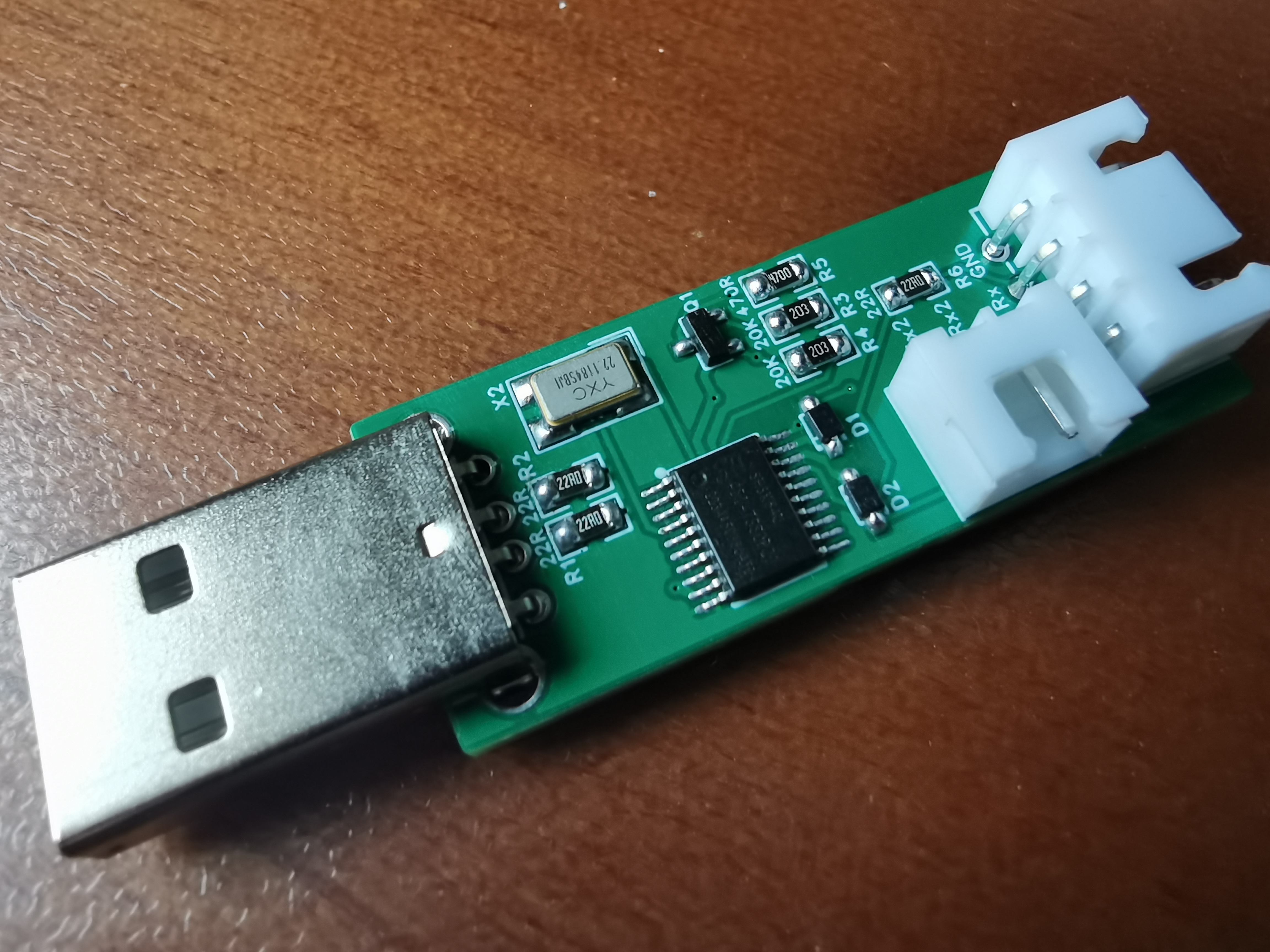
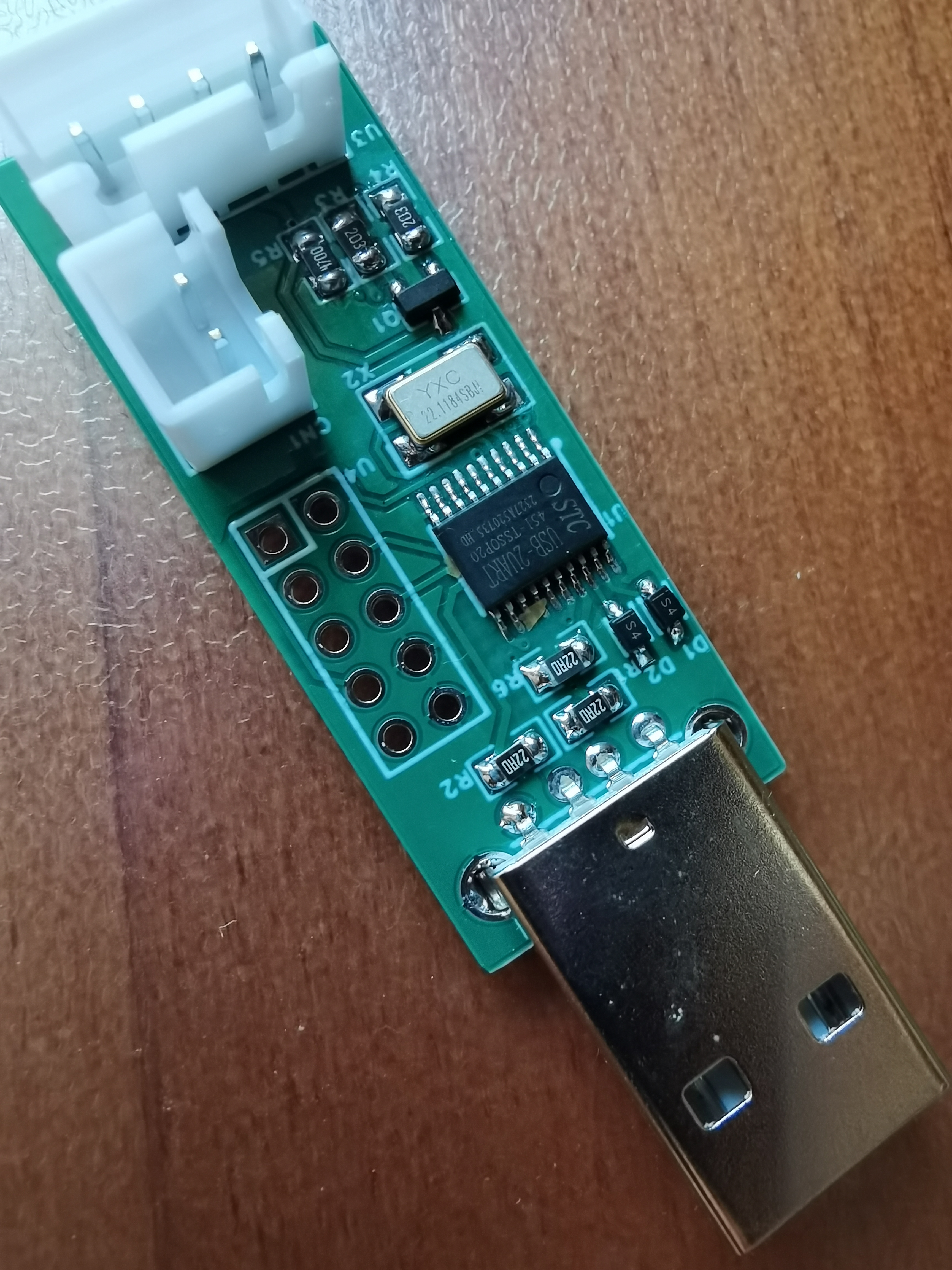
[Ultra-mini] USB to Dual Serial Port Based on STC Microcontroller
[Verified] Ultra-miniature, low-cost USB to dual serial port adapter based on STC microcontroller, compatible with multiple STC microcontrollers.
This serial port programmer is based on an STC microcontroller, specifically the STC8H8K64U chip, packaged in a TSSOP20 package. Its overall size is only 1.65*4.11cm. It also features automatic power-on/off functionality. All resistors and capacitors are 0805 packages for easy soldering. A 5*5mm QR code slot is provided. The overall cost is approximately 4-5 yuan.
The following models are available as USB-to-dual-serial converters:
STC8H2K08U-45I-TSSOP20
, STC8H2K12U 2CDC+HID-TSSOP20
, STC8H8K64U-45I-TSSOP20 (verified),
and STC USB-2UART-TSSOP20 (verified).
The latest versions of these all come with a USB-to-dual-serial converter pre-installed. Click here to download the latest STC8H datasheet.
Note: If using an older version of the STC8H8K64U, please flash the latest USB-to-dual-serial open-source program provided by STC beforehand to prevent recognition issues after soldering. Firmware download link.

The automatic power-on/off section uses the SI2301 MOSFET, but the AO3401 can be used as an alternative.
If you need to use a transistor to achieve automatic power-on/off, you can modify part of the circuit according to the datasheet.
STC USB-2UART Layout:

STC8H8K64U Layout:
Test PCB Layout:
A1, USB CDC to Dual Serial Port Open Source Program - Create an Automatic Power-Off and Power-On Programmer (Example from STC Official Website).zip
PDF_【Ultra-Mini】USB to Dual Serial Port Based on STC Microcontroller.zip
Altium_【Ultra-Mini】USB to Dual Serial Port Based on STC Microcontroller.zip
PADS_【Ultra-Mini】USB to Dual Serial Port Based on STC Microcontroller.zip
BOM_【Ultra-Mini】USB to Dual Serial Port Based on STC Microcontroller.xlsx
93881
STC8H8K64U Robot Arm Cart Bluetooth Control Board
An eight-channel PWM controller based on STC8H8K64U
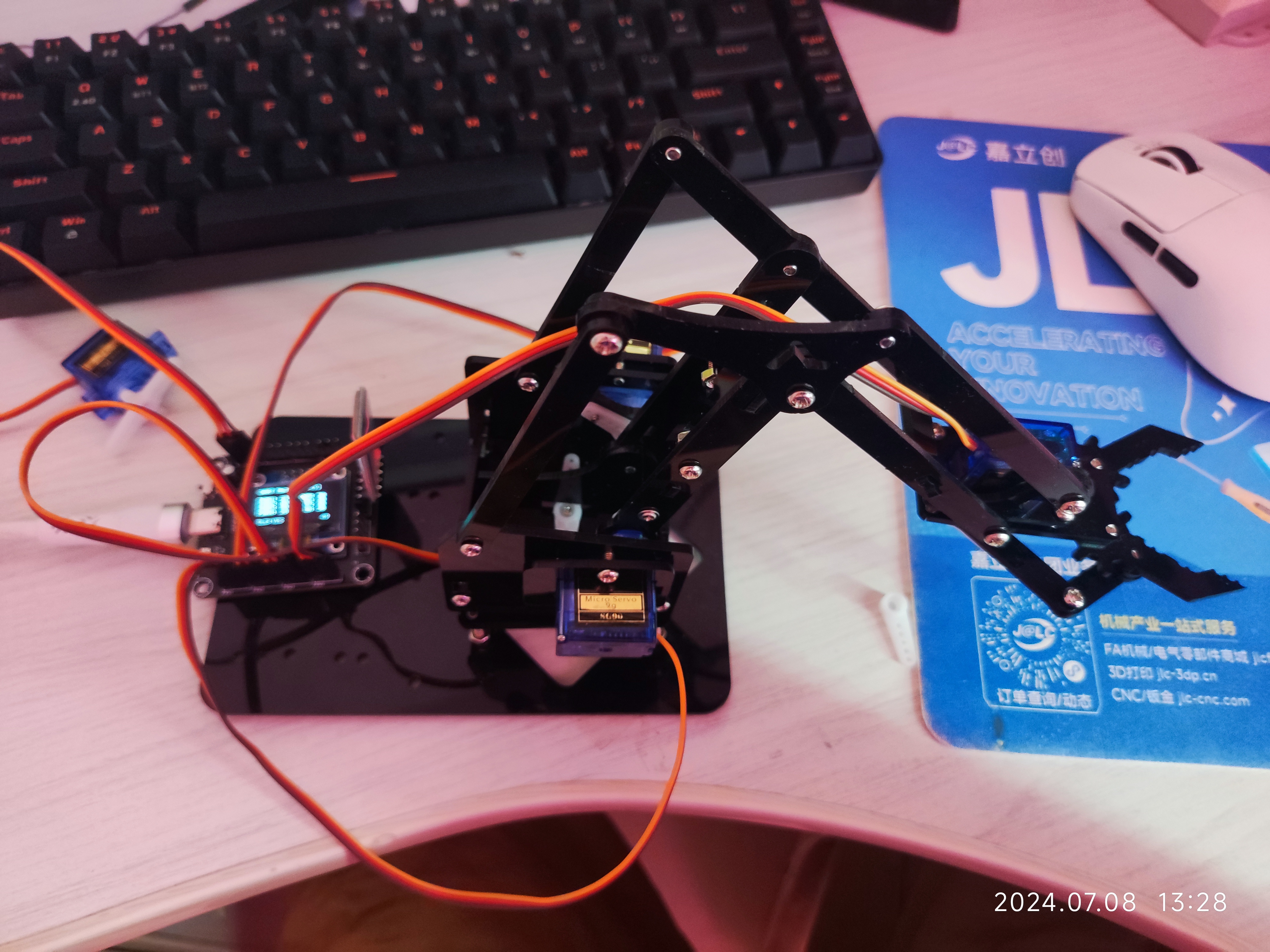
This STC8H8K64U-based quadruped robot arm/360-degree servo motor Bluetooth control board
can be used as a control board for servo-based quadruped robots, robotic arms, and cars. It allows for convenient modification and monitoring of various parameters via Bluetooth, and also enables debugging of all PWM-based modules. It features 8 adjustable duty cycle and period PWM channels, and further functionality can be achieved through code modification.
Advantages include:
1. Small size, occupying less than two bottle caps (51mm x 46mm);

2. An added OLED display module for convenient debugging and increased expandability,
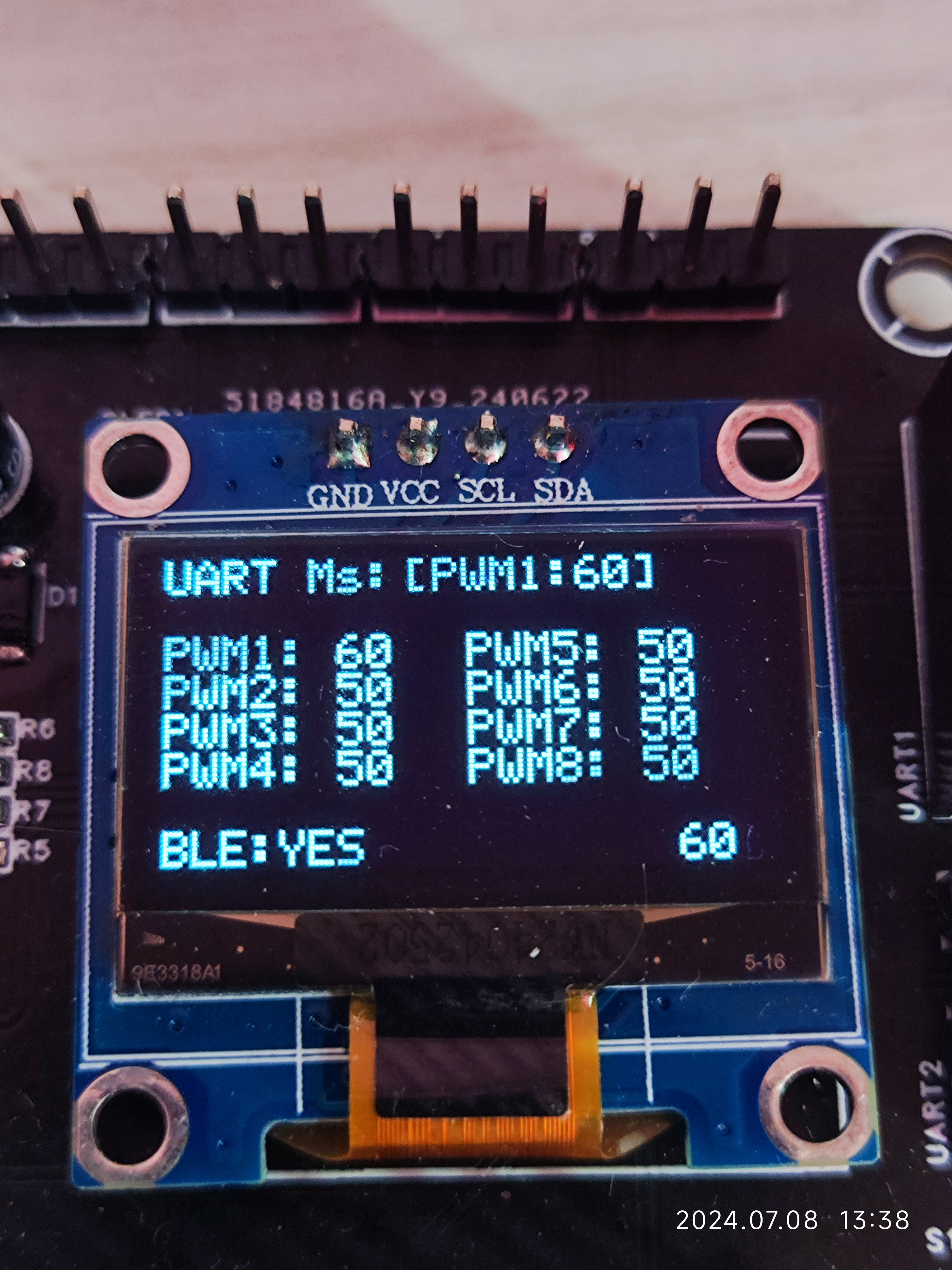
displaying current serial port reception information (UART, MS) ,
duty cycle of the 8 PWM channels,
Bluetooth connection status,
and quick preview of currently modified PWM values
; 3. Convenient Bluetooth module control, using a mobile phone as a remote control.
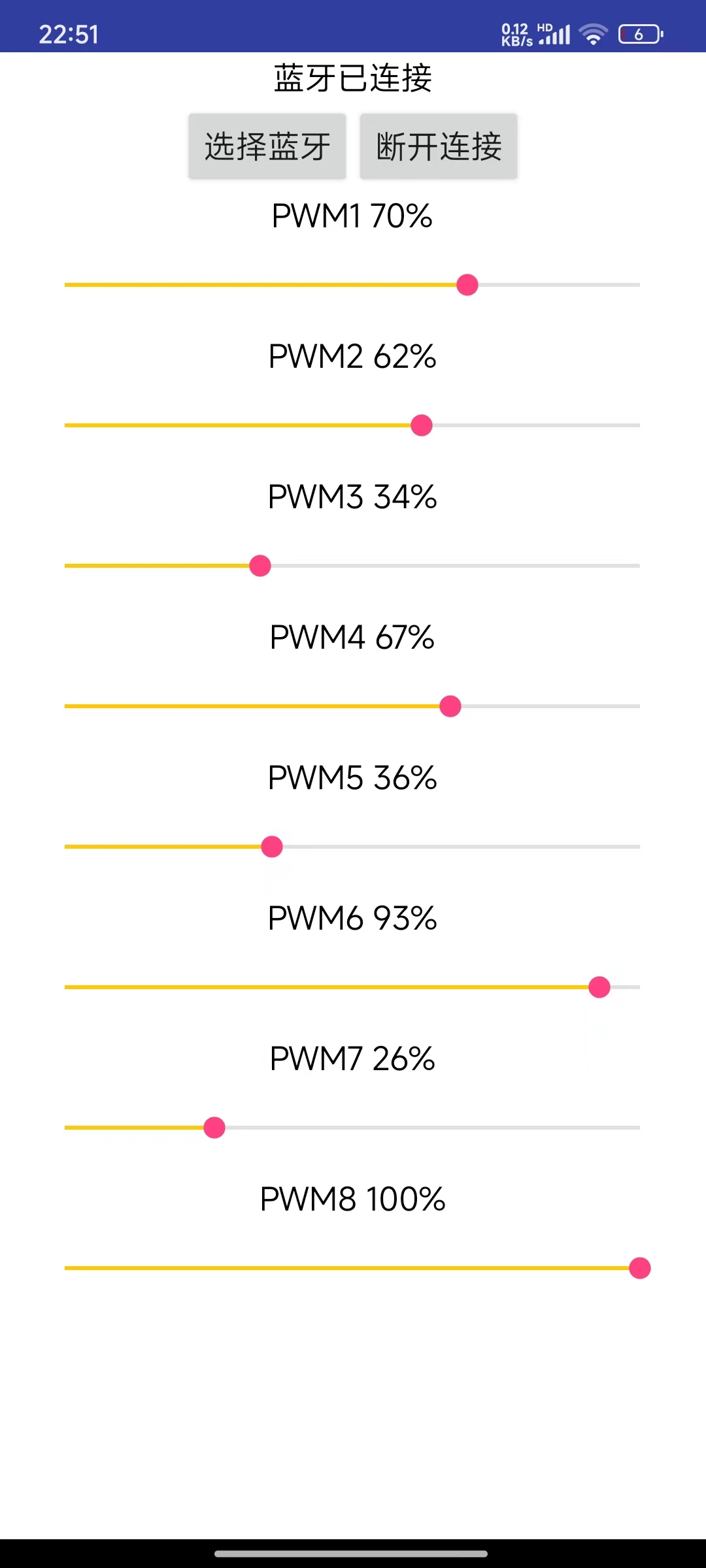
This app is written using App Inventor's visual programming interface and only supports basic functions,
controlling 8 PWM channels via Bluetooth modules (HC-05, JDY-31, etc.)
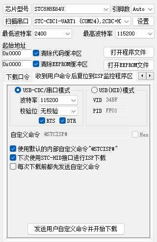
; 4. Utilizing STC's USB-to-serial conversion function, it allows direct USB program download, supports uninterrupted downloading, and facilitates code debugging.
A physical demonstration is available (see attached video).
appinventor core board host computer project.aia
Launch animation.mp4
Robotic arm hands-on control.mp4
STC8H code.zip
PDF_STC8H8K64U Robotic Arm/Car Bluetooth Control Board.zip
Altium_STC8H8K64U Robot Arm/Car Bluetooth Control Board.zip
PADS_STC8H8K64U Robot Arm/Car Bluetooth Control Board.zip
BOM_STC8H8K64U Robot Arm/Car Bluetooth Control Board.xlsx
93882
STC8 Minimum System Development Board
STC8 Minimum System Development Board
All I/O ports have been brought out.
I2C, SPI, USART2, USART3, and USART4 I/O ports are also separately brought out for easy module use.
To program, simply pull the BOOT button low and power on again.
LED2 blinks by default upon power-on; the blinking can be controlled via the keyLeft button.
LED3 is off by default; its on/off state can be controlled via the keyRight button.
The test program is attached and can be downloaded and programmed for testing and verification.
Demo video address:
https://www.bilibili.com/video/BV1G3hoeDELZ
stc8.hex
PDF_stc8 Minimal System Development Board.zip
Altium_stc8 Minimal System Development Board.zip
PADS_stc8 Minimal System Development Board.zip
BOM_stc8 Minimal System Development Board.xlsx
93884
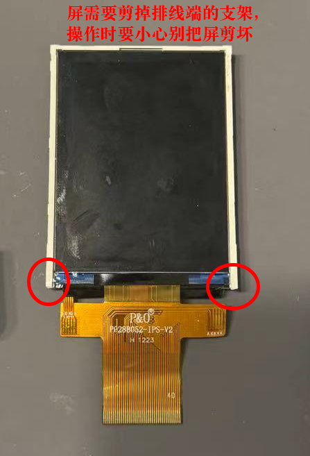
Miyoo Horizontal Version 2.8 with Joystick
Miyoo 2.8 horizontal scrolling game with joystick, after flashing CFW firmware, can smoothly play GBA, PS1 and some arcade games.
First of all, thank you to the original open-source project released by "Don't be disappointed" (QQ group number: 514419296)! https://oshwhub.com/sunnygold/2.4cun-Miyooheng-ban-zhang-ji
This modified circuit was based on some adjustments made to the components I had on hand, and an analog joystick circuit was added (not a firmware modification, but rather the implementation using two comparators connected to the original buttons). The firmware can be flashed with Situ's open-source firmware or miyoocfw (https://github.com/TriForceX/MiyooCFW).
(The casing has only been tested with FDM PETG 0.15mm precision printing; photopolymerization has not been tested, so it's unclear if it will work.)


Shell STL.zip
Main component purchase address.xlsx
PDF_Miyoo Horizontal Version 2.8 with Joystick.zip
Altium_Miyoo Horizontal Scrolling 2.8 with Joystick.zip
PADS_Miyoo Horizontal Scrolling 2.8 with Joystick.zip
BOM_Miyoo Horizontal Scrolling 2.8 with Joystick.xlsx
93886
electronic


 京公网安备 11010802033920号

 EKMQ421VSN391MR40S


